EP0798705B1 - Objective lens driving apparatus - Google Patents
Objective lens driving apparatus Download PDFInfo
- Publication number
- EP0798705B1 EP0798705B1 EP96309560A EP96309560A EP0798705B1 EP 0798705 B1 EP0798705 B1 EP 0798705B1 EP 96309560 A EP96309560 A EP 96309560A EP 96309560 A EP96309560 A EP 96309560A EP 0798705 B1 EP0798705 B1 EP 0798705B1
- Authority
- EP
- European Patent Office
- Prior art keywords
- objective lens
- lens holder
- driving apparatus
- coils
- holder
- Prior art date
- Legal status (The legal status is an assumption and is not a legal conclusion. Google has not performed a legal analysis and makes no representation as to the accuracy of the status listed.)
- Expired - Lifetime
Links
- 230000003287 optical effect Effects 0.000 claims description 48
- 230000005291 magnetic effect Effects 0.000 claims description 25
- 230000005484 gravity Effects 0.000 claims description 6
- 239000000725 suspension Substances 0.000 claims description 2
- 238000010276 construction Methods 0.000 description 16
- 230000000694 effects Effects 0.000 description 5
- 239000000696 magnetic material Substances 0.000 description 5
- XEEYBQQBJWHFJM-UHFFFAOYSA-N Iron Chemical compound [Fe] XEEYBQQBJWHFJM-UHFFFAOYSA-N 0.000 description 4
- 238000006073 displacement reaction Methods 0.000 description 4
- 229910000906 Bronze Inorganic materials 0.000 description 3
- 206010010071 Coma Diseases 0.000 description 3
- OAICVXFJPJFONN-UHFFFAOYSA-N Phosphorus Chemical compound [P] OAICVXFJPJFONN-UHFFFAOYSA-N 0.000 description 3
- 229910000831 Steel Inorganic materials 0.000 description 3
- 230000004075 alteration Effects 0.000 description 3
- 239000010974 bronze Substances 0.000 description 3
- KUNSUQLRTQLHQQ-UHFFFAOYSA-N copper tin Chemical compound [Cu].[Sn] KUNSUQLRTQLHQQ-UHFFFAOYSA-N 0.000 description 3
- 238000000034 method Methods 0.000 description 3
- 229910001220 stainless steel Inorganic materials 0.000 description 3
- 239000010935 stainless steel Substances 0.000 description 3
- 239000010959 steel Substances 0.000 description 3
- 239000004593 Epoxy Substances 0.000 description 2
- 230000003466 anti-cipated effect Effects 0.000 description 2
- 210000003298 dental enamel Anatomy 0.000 description 2
- 238000010586 diagram Methods 0.000 description 2
- 238000005516 engineering process Methods 0.000 description 2
- 239000003302 ferromagnetic material Substances 0.000 description 2
- 229910052742 iron Inorganic materials 0.000 description 2
- 239000000463 material Substances 0.000 description 2
- 230000007935 neutral effect Effects 0.000 description 2
- 239000004065 semiconductor Substances 0.000 description 2
- RYGMFSIKBFXOCR-UHFFFAOYSA-N Copper Chemical compound [Cu] RYGMFSIKBFXOCR-UHFFFAOYSA-N 0.000 description 1
- 230000002411 adverse Effects 0.000 description 1
- 238000005452 bending Methods 0.000 description 1
- 239000010949 copper Substances 0.000 description 1
- 229910052802 copper Inorganic materials 0.000 description 1
- 230000004907 flux Effects 0.000 description 1
- 238000010438 heat treatment Methods 0.000 description 1
- 239000011810 insulating material Substances 0.000 description 1
- 238000009413 insulation Methods 0.000 description 1
- 239000012212 insulator Substances 0.000 description 1
- 150000002505 iron Chemical class 0.000 description 1
- 238000010030 laminating Methods 0.000 description 1
- 230000005415 magnetization Effects 0.000 description 1
- 230000004048 modification Effects 0.000 description 1
- 238000012986 modification Methods 0.000 description 1
- 230000010355 oscillation Effects 0.000 description 1
- 239000004033 plastic Substances 0.000 description 1
- 229920003023 plastic Polymers 0.000 description 1
- 238000011084 recovery Methods 0.000 description 1
- 239000011347 resin Substances 0.000 description 1
- 229920005989 resin Polymers 0.000 description 1
- 230000000087 stabilizing effect Effects 0.000 description 1
- 239000003190 viscoelastic substance Substances 0.000 description 1
Images
Classifications
-
- G—PHYSICS
- G11—INFORMATION STORAGE
- G11B—INFORMATION STORAGE BASED ON RELATIVE MOVEMENT BETWEEN RECORD CARRIER AND TRANSDUCER
- G11B7/00—Recording or reproducing by optical means, e.g. recording using a thermal beam of optical radiation by modifying optical properties or the physical structure, reproducing using an optical beam at lower power by sensing optical properties; Record carriers therefor
- G11B7/08—Disposition or mounting of heads or light sources relatively to record carriers
- G11B7/09—Disposition or mounting of heads or light sources relatively to record carriers with provision for moving the light beam or focus plane for the purpose of maintaining alignment of the light beam relative to the record carrier during transducing operation, e.g. to compensate for surface irregularities of the latter or for track following
- G11B7/0925—Electromechanical actuators for lens positioning
- G11B7/0932—Details of sprung supports
-
- G—PHYSICS
- G11—INFORMATION STORAGE
- G11B—INFORMATION STORAGE BASED ON RELATIVE MOVEMENT BETWEEN RECORD CARRIER AND TRANSDUCER
- G11B7/00—Recording or reproducing by optical means, e.g. recording using a thermal beam of optical radiation by modifying optical properties or the physical structure, reproducing using an optical beam at lower power by sensing optical properties; Record carriers therefor
- G11B7/08—Disposition or mounting of heads or light sources relatively to record carriers
- G11B7/09—Disposition or mounting of heads or light sources relatively to record carriers with provision for moving the light beam or focus plane for the purpose of maintaining alignment of the light beam relative to the record carrier during transducing operation, e.g. to compensate for surface irregularities of the latter or for track following
- G11B7/0925—Electromechanical actuators for lens positioning
- G11B7/0935—Details of the moving parts
-
- G—PHYSICS
- G11—INFORMATION STORAGE
- G11B—INFORMATION STORAGE BASED ON RELATIVE MOVEMENT BETWEEN RECORD CARRIER AND TRANSDUCER
- G11B7/00—Recording or reproducing by optical means, e.g. recording using a thermal beam of optical radiation by modifying optical properties or the physical structure, reproducing using an optical beam at lower power by sensing optical properties; Record carriers therefor
- G11B7/08—Disposition or mounting of heads or light sources relatively to record carriers
- G11B7/09—Disposition or mounting of heads or light sources relatively to record carriers with provision for moving the light beam or focus plane for the purpose of maintaining alignment of the light beam relative to the record carrier during transducing operation, e.g. to compensate for surface irregularities of the latter or for track following
- G11B7/0925—Electromechanical actuators for lens positioning
- G11B7/0933—Details of stationary parts
Definitions
- This invention relates to an objective lens driving apparatus used for recording and reproducing data in respect of an information recording medium such as an optical disk.
- optical disk devices are widely employed in which data is stored and retrieved using a laser beam.
- Typical examples are compact disk device (CD) and laser disk device (LD).
- optical disk devices have come to be employed as storage devices for computers.
- a laser beam is focused onto the optical disk surface by an objective lens to form a spot.
- the smaller the size of this spot the greater the recording density of the optical disk that can be achieved.
- recording density increases. Therefore, new technology such as DVD, requires ever smaller spot sizes.
- the optical axis of the objective lens is as near as possible perpendicular to the optical disk surface, so as to produce a condition in which little coma aberration can occur.
- Coma aberration may occur if the objective lens is out of alignment, for example, or if the optical disk is out of alignment because of, for example, warping.
- a known objective lens drive construction whereby such control can be achieved involves supporting the objective lens for example by means of four wires.
- Such an objective lens driving device is constructed so as to make possible not only displacement of the focusing direction and the tracking direction but also axial rotary displacement for correcting a tilt of the optical axis of the objective lens, by means of focusing coils and tracking coils arranged at the periphery of the objective lens.
- JP-A-03/137,831 describes a two wire support for the lens holder and US-5,301,175 describes a four wire support for the lens holder.
- an object of this invention is to provide an objective lens driving apparatus with a simple construction whereby correction can be performed not just in the focusing direction and tracking direction but also of biaxial rotation producing tilting of the optical axis.
- an objective lens driving apparatus comprises:
- the objective lens holder can be constituted so as to provide a magnetic property. Also, it is possible to provide at least three or more focusing coils for driving said objective lens holder in the optical axis direction provided in a non-contacting relationship with said objective lens holder. Also, it is possible to provide a tracking coil for driving said objective lens holder in a direction perpendicular to the optical axis provided in a non-contacting relationship with said objective lens.
- the wire can be constituted so as to extend in a direction perpendicular to the optical axis direction of said objective lens.
- the objective lens holder may be constituted so that its center of gravity lies on the line of extension of said wire.
- the objective lens holder may include a permanent magnet.
- the objective lens holder may be constituted so as to be affected magnetic attractive force in at least the direction in which the tension in said wire acts.
- the objective lens holder is formed with a curved surface shape on the side facing said coils.
- the objective lens which is supported on the object lens holder can be suspended and supported by a very simple construction such as to permit biaxial rotation components generating tilt of the optical axis.
- the tilt of the objective lens can therefore be corrected so coma aberration can be reduced, making possible high-density recording and reproducing of information.
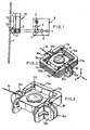
- Fig. 1 is a constructional diagram showing the overall construction of an objective lens driving apparatus.
- Fig. 2 is a perspective view showing a major portion of a first embodiment of an objective lens driving apparatus.
- Fig. 3 is a perspective view with a component shown in Fig. 2 partially removed.
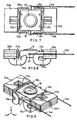
- Fig. 4 is a plan view of Fig. 2.
- Fig. 5 is a cross-sectional view along the line A-A of Fig. 4.
- Fig. 6 is a cross-sectional view along the line B-B in Fig. 4.
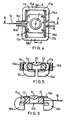
- Fig. 7 is a plan view showing a major portion of a different arrangement of an objective lens driving apparatus ;
- Fig. 8 is a side view of Fig. 7.
- Fig. 9 is a perspective view of Fig. 7.
- Fig. 1 is a constructional diagram showing the overall construction of a first embodiment of an objective lens driving apparatus.
- Fig. 2 is a perspective view showing a major portion of an objective lens driving apparatus.
- Fig. 3 is a perspective view with a component in Fig. 2 partially removed.
- Fig. 4 is a plan view of Fig. 2.
- Fig. 5 is a cross-sectional view along the line A-A of Fig. 4.
- Fig. 6 is a cross-sectional view along the line B-B in Fig. 4.
- a disk 1 provided for recording/reproducing information is held by chucking means such as a magnetic chuck on a spindle motor 2 that is fixed to a base (not shown) so that it can be driven in rotation in stable fashion by the spindle motor 2 during recording or reproducing information.
- the disk 1 may be any optical information recording medium such as an optical disk (for example CD-ROM, DVD etc.), a magneto-optical disk, or a phase-change disk etc.
- This optical unit 8 is fixed onto a base.
- the laser beam emitted from the semiconductor laser 3 is changed in direction by 90° by deflecting prism 7 after passing through collimating lens 5, and is output from optical unit 8.
- This laser beam is changed in direction by 90° by the reflecting mirror surface of a mirror 9, whence it is directed to objective lens 10, which is arranged at the top of optical head 20.
- the laser beam is then focused onto a recording track on disk 1 by the objective lens 10, to form a focal point.
- the reflected light beam from disk 1 returns to objective lens 10 and, passing by way of mirror 9, passes through deflecting prism 7 to be returned to photo detector 4.
- Objective lens 10 that focuses the laser beam onto the recording track of disk 1 is fixed on the upper surface of an objective lens holder 13.
- Objective lens holder 13 is formed of a permanent magnet whose direction of magnetization is set such that the left and right side faces thereof shown in Fig. 4 are respectively an N pole and an S pole. Also, the side faces corresponding to this N pole and S pole are formed with a curved shape such that they curve gradually towards the edge (see Fig. 4 and Fig. 6).
- Flexible body 14 is constituted of single wire and is made of non-magnetic material such as for example stainless steel or phosphor bronze, and suspends and supports objective lens holder 13. Also, the center of gravity of the entire movable unit including objective lens 10, objective lens holder 13, and focusing coil and tracking coil (to be described) are arranged on the line of extension of the flexible body 14 (in the vicinity of the center of objective lens 10). The other end of flexible body 14 is fixed to optical head 20.
- Yokes 15a, 15b which are roughly of U-shaped cross-section are arranged symmetrically at the periphery of objective lens holder 13.
- yokes 15a, 15b a plurality of thin sheets of ferromagnetic material (for example steel sheet) are formed in laminated condition with insulators (e.g. epoxy or enamel etc.) interposed between them.
- Yokes 15a, 15b are fixed so as to be integral with optical head 20 at their lower surface.
- Respective focusing coils 16a, 16b, 16c, 16d are fixed in the vicinity of each end of yokes 15a, 15b.
- Focusing coils 16a, 16b, 16c, 16d are constituted of flat-wound thin coils having a shape bent from the vicinity of their middle.
- Focusing coils 16a, 16b, 16c, 16d are electrically insulated from each other, the yokes 15a, 15b, and the objective lens holder 13. Also, as shown in Fig. 3 and Fig.
- tracking coils 17a, 17b, 17c, 17d which are likewise flat-wound, are arranged at the surface of focusing coils 16a, 16b, 16c, 16d and, as shown in Fig. 3 and Fig. 4, are adhesively fixed in the vicinity of the ends of focusing coils 16a, 16b, 16c, 16d.
- the side edges of tracking coils 17a, 17b, 17c, 17d i.e. the sides thereof nearer to objective lens holder 13
- Tracking coils 17a, 17b, 17c, 17d are electrically insulated from the focusing coils 16a, 16b, 16c, 16d as well as the yokes 15a, 15b and the objective lens holder 13.
- auxiliary yoke 18 consisting of ferromagnetic material (for example steel material like iron) is fixed between yokes 15a, 15b and in a position clamped by the two focusing coils 16a, 16b.
- Auxiliary yoke 18 is opposite the N pole of objective lens holder 13 and is arranged on the line of extension of flexible body 14.
- a recorded information signal, a focus offset signal and a track offset signal etc. are generated from the reflected light beam picked up by photo detector 4.
- the positional offset in the focusing direction of objective lens 10 is detected using the focus offset signal and a control operation is performed so as to supply prescribed currents to focusing coils 16a, 16b, 16c, 16d such as to correct this positional offset.
- the positional offset in the tracking direction of objective lens 10 is detected by means of the track offset signal, and a control operation is performed by applying voltages to the linear motor coil (coil for driving optical head 20: not shown) and tracking coils 17a, 17b, 17c, 17d in order to correct this positional offset.
- objective lens holder 13 carrying the objective lens 10 is supported by an flexible body 14, which is constituted of a single wire. Consequently, excluding the linear motion component in the axial direction of flexible body 14, objective lens holder 13 is allowed five degrees of freedom (linear motion component in the X-axis direction, rotational component about the X-axis direction, rotational component about the Y-axis direction, linear motion component in the Z-axis direction, and rotational component about the Z-axis direction, as indicated in Fig. 2).
- focus driving force Ff Ffa + Ffb + Ffc + Ffd
- the laser beam can be focused at a focal point on disk 1 by displacing objective lens 10 in the optical axis direction (Z-axis direction) using this focus driving force Ff.
- objective lens 10 can be displaced in the direction (X-axis direction) respectively perpendicular to the axial direction of the flexible body 14 and the optical axis direction of objective lens 10, so that the focal point of the laser beam can be made to coincide with the desired track on disk 1.
- a rotational component is generated on the objective lens 10 about its optical axis (about the Z-axis), but, if objective lens 10 has an axially symmetric shape about the optical axis, there is no particular need to positively control this rotational component. It should be noted that, since this rotational component is generated about the optical axis of objective lens 10, it cannot change its optical characteristics and cannot have an adverse effect on recording and reproducing information etc.
- the center of gravity of objective lens holder 13 is on the optical axis of objective lens 10
- objective lens holder 13 yokes 15a, 15b, focusing coils 16a, 16b, 16c, 16d are plane-symmetric with respect to the two planes represented by the plane containing the optical axis of objective lens 10 and flexible body 14 (Y-Z plane), and the plane perpendicular to this (X-Z plane).
- the rotational force 9 x about the X axis can be expressed by the following equation.
- ⁇ x (Ffa + Ffb) - (Ffc + Ffd)
- the rotational force 6 y about the Y-axis can be expressed by the following equation.
- ⁇ y (Ffa + Ffc) - (Ffb + Ffd)
- the optical axis of objective lens 10 can be tilted in any desired direction by controlling focusing coils 16a, 16b, 16c, 16d using the relationships shown in equations (2) and (3). Position control of objective lens 10 can therefore be achieved such as to maintain the optical axis of objective lens 10 in a condition that is always perpendicular with respect to the surface of disk 1.
- equations (2) and (3) can be adopted practically without modification.
- the construction is such that the three axes are controlled by four focusing coils 16a, 16b, 16c, and 16d.
- the device could be constituted using only three focusing coils.
- the two side faces (faces where the magnetic poles are provided) of objective lens holder 13 are formed in curved shape so that they gradually curve towards the edges. If these side faces were to be made planar, when for example the optical axis of the objective lens 10 was tilted or was displaced in the tracking direction, the magnetic attractive force on yokes 15a, 15b would become locally larger. But in general, it is known that the attractive force between a magnet and a yoke shows an abrupt increase where the distance between these two gets small.
- the magnetic attractive force of objective lens holder 13 and yokes 15a, 15b may exceed the elastic stability force of flexible body 14, with the result that objective lens holder 13 will be forced into contact with the stopper.
- the risk could arise that, in the worst case, the electromagnetic driving force produced by the coil might be exceeded, resulting in a condition from which recovery is impossible.
- an auxiliary yoke 18 is arranged on the opposite side (between yokes 15a, 15b) to flexible body 14, sandwiching objective lens 10. Due to the mounting of auxiliary yoke 18 in this way, somewhat larger magnetic attraction is applied to objective lens holder 13 on the side facing the auxiliary yoke 18 than on the side facing flexible body 14, so that flexible body 14 is normally under tension. Controlling the position of objective lens holder 13 is thereby greatly facilitated since it is achieved by positively removing flexure of flexible body 14.
- the magnetic attractive force generated on the right side of line A-A in Fig. 4 may be made stronger since the magnetic circuit formed by objective lens holder 13 and yokes 15a, 15b is asymmetric as between the right and left side of this line A-A.
- the same effect can thereby be anticipated as in the case where an auxiliary yoke 18 is provided.
- the distance between the magnetic pole face S and the yoke on the side facing the flexible body 14 i.e. the magnetic gap
- methods such as changing the shape of the yoke could also be adopted.
- the magnetic attractive force acting between objective lens holder 13 and yokes 15a, 15b becomes smaller on the side facing the flexible body 14. Consequently, when objective lens holder 13 is displaced in the optical axis direction (Z-axis direction) of objective lens 10, the attractive force in the Z-axis direction acting on objective lens holder 13 is smaller on the side facing flexible body 14. It is therefore desirable to correct the tilt of the optical axis of objective lens 10 by some means such as adjustment of the quantity of current flowing to the four focusing coils 16a, 16b, 16c, 16d, such as to make the magnetic attractive force of appropriate magnitude.
- Interference wherein rotational movement about the X-axis is produced by actuation of objective lens 10 in the optical axis direction (Z-axis direction) can thereby be alleviated, so enabling effective control to be achieved by an uncomplicated control system without having to consider such interference.
- the effect may be anticipated that it is possible to prevent the displacement of the objective lens holder 13 being larger on the opposite side (N pole side) than on the side facing the flexible body 14 (S pole side) when objective lens holder 13 is actuated in the tracking direction (X axis direction).
- yokes 15a, 15b in this embodiment are formed by laminating a plurality of thin iron sheets with insulating material (for example epoxy or enamel etc.) arranged between them. If the yokes were to be formed of a single material, heating of the interior of the yokes would be produced by generation of eddy current in the interior during movement of the objective lens holder 13, depending on the speed of this movement. However, thanks to the use of yokes made of laminated iron sheets with insulation, the generation of eddy current can be restrained.
- insulating material for example epoxy or enamel etc.
- auxiliary yoke 18 prevents occurrence of oscillation of objective lens holder 13, thus enabling reliable positional control to be achieved.
- the flexible body 14 of this embodiment consisted of single wire made of a non-magnetic material such as stainless steel or phosphor bronze.
- Fig. 7 is a plan view of a major portion of an objective lens driving apparatus.
- Fig. 8 is a side view thereof, and
- Fig. 9 is a perspective view thereof.
- the main feature of this arrangement is that the objective lens is suspended and supported by a couple (two) of flexible bodies.
- Objective lens holder 21 on which objective lens 10 is carried is suspended and supported by a couple of flexible bodies 14a, 14b arranged in a plane (X-Y plane) passing through the center of gravity of objective lens holder 21 and perpendicular to the optical axis of objective lens 1.
- objective lens holder 21 consists of a permanent magnet, but, as shown in Fig. 7, it is magnetized such that an N pole and S pole are formed respectively at the left and right side faces.
- Yokes 22a, 22b fixed to a base are arranged at positions opposite to the magnetic pole faces of objective lens holder 21.
- Four focusing coils 16a, 16b, 16c, 16d and two tracking coils 17a, 17b are fixed to yokes 22a, 22b.
- These focusing coils 16a, 16b, 16c, 16d are constituted by bending flat-wound insulated thin coils in a shape which is bent at two locations alternately. As shown in Fig. 8 and Fig. 9, the upper edges of focus coils 16a, 16b, 16c, 16d are fixed by means such as adhesion to yokes 22a, 22b facing the inside face of yokes 22a, 22b and the side face (magnetized face) of objective lens holder 21.
- tracking coils 17a, 17b which are likewise flat-wound insulated coils, are fixed to the surface of focusing coils 16a, 16b, 16c, 16d.
- tracking coil 17a is adhesively fixed so as to span focusing coils 16a, 16b
- tracking coil 17b is adhesively fixed so as to span focus coils 16c, 16d, respectively.
- Both side edges of tracking coils 17a, 17b are exactly facing the side faces (magnetized face) of objective lens holder 21, one side edge facing the N pole, while the other side edge faces the S pole, respectively.
- flexible wire can be made not only of stainless steel but also of phosphor bronze, copper, and steel etc.
- viscoelastic material such as gel could be put on flexible wire for stabilizing vibration.
- the partial diameter of flexible wire could be changed in order to control and adjust the ratio between rotational stiffness and translational stiffness.
- reducing the diameter of root portion of the flexible wire is effective.
- the objective lens holder in this embodiment was constituted using a permanent magnet
- a construction could be adopted in which a permanent magnet was mounted adhesively onto an objective lens holder formed of for example non-magnetic material such as resin.
- all the coils could be mounted on the objective lens holder, the permanent magnet and yoke being mounted on the yoke side. If such a construction is adopted, there is no need to make the magnetic pole faces of the permanent magnet curved surfaces.
- an objective lens driving apparatus can be implemented that is capable of correcting not only the focusing direction and tracking direction but also biaxial rotation generating tilt of the optical axis, while yet having a simple construction.
Landscapes
- Optical Recording Or Reproduction (AREA)
Description
- This invention relates to an objective lens driving apparatus used for recording and reproducing data in respect of an information recording medium such as an optical disk.
- As is well known, optical disk devices are widely employed in which data is stored and retrieved using a laser beam. Typical examples are compact disk device (CD) and laser disk device (LD). Recently, optical disk devices have come to be employed as storage devices for computers.
- When information is recorded onto or reproduced from an optical disk, a laser beam is focused onto the optical disk surface by an objective lens to form a spot. The smaller the size of this spot, the greater the recording density of the optical disk that can be achieved. As technology advances, recording density increases. Therefore, new technology such as DVD, requires ever smaller spot sizes.
- Furthermore, to maintain the size of the spot as small as possible, it is important to exercise control such that the optical axis of the objective lens is as near as possible perpendicular to the optical disk surface, so as to produce a condition in which little coma aberration can occur. Coma aberration may occur if the objective lens is out of alignment, for example, or if the optical disk is out of alignment because of, for example, warping.
- A known objective lens drive construction whereby such control can be achieved involves supporting the objective lens for example by means of four wires. Such an objective lens driving device is constructed so as to make possible not only displacement of the focusing direction and the tracking direction but also axial rotary displacement for correcting a tilt of the optical axis of the objective lens, by means of focusing coils and tracking coils arranged at the periphery of the objective lens.
- However, in order to correct a tilt of the optical axis of the objective lens in high accuracy, desired biaxial rotary displacement should occur. Furthermore, large variations in wire shape result in imbalance of the drive characteristic, making it very difficult to achieve the desired operating characteristic. Thus the device ends up becoming impracticable.
- JP-A-03/137,831 describes a two wire support for the lens holder and US-5,301,175 describes a four wire support for the lens holder.
- As described above, in conventional objective lens driving apparatus, the construction was complicated, so miniaturization of the device was impeded, and it was difficult to obtain a high control range and high-accuracy position.
- Accordingly an object of this invention is to provide an objective lens driving apparatus with a simple construction whereby correction can be performed not just in the focusing direction and tracking direction but also of biaxial rotation producing tilting of the optical axis.
- In order to achieve this object, an objective lens driving apparatus according to this invention comprises:
- an objective lens for directing a laser beam onto an optical information recording medium; and
- an objective lens holder for holding said objective lens, characterised by
- a suspension system consisting essentially of single wire, one end thereof being connected to said objective lens holder, and
- an electromagnetic driver for effecting electromagnetic force to said objective lens holder.
-
- It should be noted that the objective lens holder can be constituted so as to provide a magnetic property. Also, it is possible to provide at least three or more focusing coils for driving said objective lens holder in the optical axis direction provided in a non-contacting relationship with said objective lens holder. Also, it is possible to provide a tracking coil for driving said objective lens holder in a direction perpendicular to the optical axis provided in a non-contacting relationship with said objective lens.
- Also, the wire can be constituted so as to extend in a direction perpendicular to the optical axis direction of said objective lens.
- The objective lens holder may be constituted so that its center of gravity lies on the line of extension of said wire. The objective lens holder may include a permanent magnet. Also, the objective lens holder may be constituted so as to be affected magnetic attractive force in at least the direction in which the tension in said wire acts.
- It should be noted that the objective lens holder is formed with a curved surface shape on the side facing said coils.
- With the invention constructed as above, the objective lens which is supported on the object lens holder can be suspended and supported by a very simple construction such as to permit biaxial rotation components generating tilt of the optical axis. The tilt of the objective lens can therefore be corrected so coma aberration can be reduced, making possible high-density recording and reproducing of information.
- Fig. 1 is a constructional diagram showing the overall construction of an objective lens driving apparatus.
- Fig. 2 is a perspective view showing a major portion of a first embodiment of an objective lens driving apparatus.
- Fig. 3 is a perspective view with a component shown in Fig. 2 partially removed.
- Fig. 4 is a plan view of Fig. 2.
- Fig. 5 is a cross-sectional view along the line A-A of Fig. 4.
- Fig. 6 is a cross-sectional view along the line B-B in Fig. 4.
- Fig. 7 is a plan view showing a major portion of a different arrangement of an objective lens driving apparatus ;
- Fig. 8 is a side view of Fig. 7.
- Fig. 9 is a perspective view of Fig. 7.
- Embodiments of this invention are described below with reference to the drawings.
- Fig. 1 is a constructional diagram showing the overall construction of a first embodiment of an objective lens driving apparatus. Fig. 2 is a perspective view showing a major portion of an objective lens driving apparatus. Fig. 3 is a perspective view with a component in Fig. 2 partially removed.
- Fig. 4 is a plan view of Fig. 2. Fig. 5 is a cross-sectional view along the line A-A of Fig. 4. Fig. 6 is a cross-sectional view along the line B-B in Fig. 4.
- A disk 1 provided for recording/reproducing information is held by chucking means such as a magnetic chuck on a spindle motor 2 that is fixed to a base (not shown) so that it can be driven in rotation in stable fashion by the spindle motor 2 during recording or reproducing information. In this embodiment, the disk 1 may be any optical information recording medium such as an optical disk (for example CD-ROM, DVD etc.), a magneto-optical disk, or a phase-change disk etc.
- A
semiconductor laser 3 that generates a laser beam that is to be directed onto disk 1, together with aphoto detector 4,collimator lens 5, condenser lens 6, anddeflection prism 7, constitutes anoptical unit 8. Thisoptical unit 8 is fixed onto a base. - The laser beam emitted from the
semiconductor laser 3 is changed in direction by 90° by deflectingprism 7 after passing through collimatinglens 5, and is output fromoptical unit 8. This laser beam is changed in direction by 90° by the reflecting mirror surface of amirror 9, whence it is directed toobjective lens 10, which is arranged at the top ofoptical head 20. The laser beam is then focused onto a recording track on disk 1 by theobjective lens 10, to form a focal point. The reflected light beam from disk 1 returns toobjective lens 10 and, passing by way ofmirror 9, passes throughdeflecting prism 7 to be returned tophoto detector 4. -
Objective lens 10 that focuses the laser beam onto the recording track of disk 1 is fixed on the upper surface of anobjective lens holder 13.Objective lens holder 13 is formed of a permanent magnet whose direction of magnetization is set such that the left and right side faces thereof shown in Fig. 4 are respectively an N pole and an S pole. Also, the side faces corresponding to this N pole and S pole are formed with a curved shape such that they curve gradually towards the edge (see Fig. 4 and Fig. 6). - One end of a wire-like
flexible body 14 is fixed to the side face of thisobjective lens holder 13.Flexible body 14 is constituted of single wire and is made of non-magnetic material such as for example stainless steel or phosphor bronze, and suspends and supportsobjective lens holder 13. Also, the center of gravity of the entire movable unit includingobjective lens 10,objective lens holder 13, and focusing coil and tracking coil (to be described) are arranged on the line of extension of the flexible body 14 (in the vicinity of the center of objective lens 10). The other end offlexible body 14 is fixed tooptical head 20. -
Yokes objective lens holder 13. Inyokes Yokes optical head 20 at their lower surface. - Respective focusing
coils yokes coils coils yokes objective lens holder 13. Also, as shown in Fig. 3 and Fig. 5, their upper edges of focusingcoils yokes yokes objective lens holder 13. - Also,
thin tracking coils coils coils coils objective lens holder 13.Tracking coils coils yokes objective lens holder 13. - An
auxiliary yoke 18 consisting of ferromagnetic material (for example steel material like iron) is fixed betweenyokes coils Auxiliary yoke 18 is opposite the N pole ofobjective lens holder 13 and is arranged on the line of extension offlexible body 14. - With an objective lens driving apparatus constructed as above, a recorded information signal, a focus offset signal and a track offset signal etc. are generated from the reflected light beam picked up by
photo detector 4. The positional offset in the focusing direction ofobjective lens 10 is detected using the focus offset signal and a control operation is performed so as to supply prescribed currents to focusingcoils objective lens 10 is detected by means of the track offset signal, and a control operation is performed by applying voltages to the linear motor coil (coil for driving optical head 20: not shown) andtracking coils - In an objective lens driving apparatus of this invention constructed in this way,
objective lens holder 13 carrying theobjective lens 10 is supported by anflexible body 14, which is constituted of a single wire. Consequently, excluding the linear motion component in the axial direction offlexible body 14,objective lens holder 13 is allowed five degrees of freedom (linear motion component in the X-axis direction, rotational component about the X-axis direction, rotational component about the Y-axis direction, linear motion component in the Z-axis direction, and rotational component about the Z-axis direction, as indicated in Fig. 2). - If now the respective driving forces of the four focusing
coils - The laser beam can be focused at a focal point on disk 1 by displacing
objective lens 10 in the optical axis direction (Z-axis direction) using this focus driving force Ff. - Furthermore, by utilizing the resultant of the driving forces of the four
tracking coils objective lens 10 can be displaced in the direction (X-axis direction) respectively perpendicular to the axial direction of theflexible body 14 and the optical axis direction ofobjective lens 10, so that the focal point of the laser beam can be made to coincide with the desired track on disk 1. - Also, a rotational component is generated on the
objective lens 10 about its optical axis (about the Z-axis), but, ifobjective lens 10 has an axially symmetric shape about the optical axis, there is no particular need to positively control this rotational component. It should be noted that, since this rotational component is generated about the optical axis ofobjective lens 10, it cannot change its optical characteristics and cannot have an adverse effect on recording and reproducing information etc. - Apart from the three degrees of freedom described above, further two degrees of freedom can be produced by the device construction of this invention. These two degrees of freedom are biaxial rotational components (about the X-axis direction and about the Y-axis direction) perpendicular to the optical axis of
objective lens 10. These degrees of freedom will be explained below. - In the construction of the embodiment shown in Fig. 2 to Fig. 6, the center of gravity of
objective lens holder 13 is on the optical axis ofobjective lens 10, andobjective lens holder 13,yokes coils objective lens 10 and flexible body 14 (Y-Z plane), and the plane perpendicular to this (X-Z plane). - The rotational force 9 x about the X axis can be expressed by the following equation.
- The optical axis of
objective lens 10 can be tilted in any desired direction by controlling focusingcoils objective lens 10 can therefore be achieved such as to maintain the optical axis ofobjective lens 10 in a condition that is always perpendicular with respect to the surface of disk 1. - It should be noted that, in this embodiment, as shown in Fig. 2 to Fig. 6, since
objective lens holder 13 andyokes - Thus, in this embodiment, the construction is such that the three axes are controlled by four focusing
coils objective lens 10 can therefore be achieved by the construction as in this embodiment employing four focusingcoils - Also, in this embodiment, the two side faces (faces where the magnetic poles are provided) of
objective lens holder 13 are formed in curved shape so that they gradually curve towards the edges. If these side faces were to be made planar, when for example the optical axis of theobjective lens 10 was tilted or was displaced in the tracking direction, the magnetic attractive force onyokes objective lens holder 13, the magnetic attractive force ofobjective lens holder 13 andyokes flexible body 14, with the result thatobjective lens holder 13 will be forced into contact with the stopper. Further, the risk could arise that, in the worst case, the electromagnetic driving force produced by the coil might be exceeded, resulting in a condition from which recovery is impossible. - That is, by making the magnetic pole faces of
objective lens holder 13 of two-dimensionally curved shape as in this embodiment, it is possible to make the magnetic attractive force ofobjective lens holder 13 andyokes Objective lens holder 13 can therefore be reliably maintained in its neutral position when the device is not actuated by utilizing the stability force offlexible body 14, and the reliability of the apparatus can thereby be increased. - It should be noted that practically the same effect as in the case of the embodiment described above can be obtained even if the magnetic pole faces (curved faces) of
objective lens holder 13 are covered with a non-magnetic material such as plastics, thereby providing the magnetic pole faces with a planar finish. Alternatively, practically the same effect as in the case of the embodiment described above can be obtained by making the magnetic pole faces of theobjective lens holder 13 of originally planar shape and finishing them to a curved-surface shape by covering them with a magnetic material. - Also, it is possible to adjust the flow of magnetic flux such that
objective lens holder 13 is restored to its neutral position by making the curvature of the magnetic pole faces ofobjective lens holder 13 smaller. - Furthermore, in this embodiment, an
auxiliary yoke 18 is arranged on the opposite side (betweenyokes flexible body 14, sandwichingobjective lens 10. Due to the mounting ofauxiliary yoke 18 in this way, somewhat larger magnetic attraction is applied toobjective lens holder 13 on the side facing theauxiliary yoke 18 than on the side facingflexible body 14, so thatflexible body 14 is normally under tension. Controlling the position ofobjective lens holder 13 is thereby greatly facilitated since it is achieved by positively removing flexure offlexible body 14. - It should be noted that the magnetic attractive force generated on the right side of line A-A in Fig. 4 may be made stronger since the magnetic circuit formed by
objective lens holder 13 andyokes auxiliary yoke 18 is provided. Specifically, the distance between the magnetic pole face S and the yoke on the side facing the flexible body 14 (i.e. the magnetic gap) can be set to be longer than the distance between the magnetic pole face N and the yoke on the opposite side. Of course, methods such as changing the shape of the yoke could also be adopted. - If any of these methods (or a combination of these methods) is adopted, the magnetic attractive force acting between
objective lens holder 13 andyokes flexible body 14. Consequently, whenobjective lens holder 13 is displaced in the optical axis direction (Z-axis direction) ofobjective lens 10, the attractive force in the Z-axis direction acting onobjective lens holder 13 is smaller on the side facingflexible body 14. It is therefore desirable to correct the tilt of the optical axis ofobjective lens 10 by some means such as adjustment of the quantity of current flowing to the four focusingcoils objective lens 10 in the optical axis direction (Z-axis direction) can thereby be alleviated, so enabling effective control to be achieved by an uncomplicated control system without having to consider such interference. - Likewise, the effect may be anticipated that it is possible to prevent the displacement of the
objective lens holder 13 being larger on the opposite side (N pole side) than on the side facing the flexible body 14 (S pole side) whenobjective lens holder 13 is actuated in the tracking direction (X axis direction). - Also, as mentioned above, yokes 15a, 15b in this embodiment are formed by laminating a plurality of thin iron sheets with insulating material (for example epoxy or enamel etc.) arranged between them. If the yokes were to be formed of a single material, heating of the interior of the yokes would be produced by generation of eddy current in the interior during movement of the
objective lens holder 13, depending on the speed of this movement. However, thanks to the use of yokes made of laminated iron sheets with insulation, the generation of eddy current can be restrained. - Furthermore, the
auxiliary yoke 18 prevents occurrence of oscillation ofobjective lens holder 13, thus enabling reliable positional control to be achieved. - Also, the
flexible body 14 of this embodiment consisted of single wire made of a non-magnetic material such as stainless steel or phosphor bronze. - A second embodiment of this invention will now be described with reference to Fig. 7 to Fig. 9. Structural elements which are identical with those of the first embodiment described above are given the same symbols and repeated description is omitted.
- Fig. 7 is a plan view of a major portion of an objective lens driving apparatus. Fig. 8 is a side view thereof, and Fig. 9 is a perspective view thereof.
- The main feature of this arrangement is that the objective lens is suspended and supported by a couple (two) of flexible bodies.
-
Objective lens holder 21 on whichobjective lens 10 is carried is suspended and supported by a couple offlexible bodies objective lens holder 21 and perpendicular to the optical axis of objective lens 1. In this arrangement also,objective lens holder 21 consists of a permanent magnet, but, as shown in Fig. 7, it is magnetized such that an N pole and S pole are formed respectively at the left and right side faces. -
Yokes objective lens holder 21. Four focusingcoils tracking coils yokes - These focusing
coils focus coils yokes yokes objective lens holder 21. - Also,
thin tracking coils coils coil 17a is adhesively fixed so as to span focusingcoils coil 17b is adhesively fixed so as to span focus coils 16c, 16d, respectively. Both side edges of trackingcoils objective lens holder 21, one side edge facing the N pole, while the other side edge faces the S pole, respectively. - With the arrangement constructed as above, since two
flexible bodies objective lens 10 about the optical axis (about the Z-axis), so, functionally, there is no difference from the first embodiment. However, since rotation about the Z-axis is structurally restrained, there is no need to form the side faces of the objective lens holder in a two-dimensionally curved surface shape as in the case of the first embodiment. It suffices if the shape of the objective lens holder is curved only in the direction seen from the cross-section shown in Fig. 8 (i.e. one dimensionally). - In the constructions described above, flexible wire can be made not only of stainless steel but also of phosphor bronze, copper, and steel etc.
- Also, viscoelastic material such as gel could be put on flexible wire for stabilizing vibration.
- Furthermore, the partial diameter of flexible wire could be changed in order to control and adjust the ratio between rotational stiffness and translational stiffness. In particular, reducing the diameter of root portion of the flexible wire is effective.
- Although the objective lens holder in this embodiment was constituted using a permanent magnet, a construction could be adopted in which a permanent magnet was mounted adhesively onto an objective lens holder formed of for example non-magnetic material such as resin.
- Also, all the coils could be mounted on the objective lens holder, the permanent magnet and yoke being mounted on the yoke side. If such a construction is adopted, there is no need to make the magnetic pole faces of the permanent magnet curved surfaces.
- As described above, with this invention, an objective lens driving apparatus can be implemented that is capable of correcting not only the focusing direction and tracking direction but also biaxial rotation generating tilt of the optical axis, while yet having a simple construction.
Claims (10)
- An objective lens driving apparatus comprising:an objective lens (10) for directing a laser beam onto an optical information recording medium (1); andan objective lens holder (13) for holding said objective lens, said driving apparatus characterised by a suspension system consisting essentially of single wire (14), one end thereof being connected to said objective lens holder; andan electromagnetic driver (15a, 15b, 16a-16d, 17a-17d, 18) for effecting electromagnetic force to said objective lens holder.
- An objective lens driving apparatus according to claim 1, wherein said objective lens holder has a magnetic property.
- An objective lens driving apparatus according to claim 2, wherein said electromagnetic driver comprises at least three focusing coils (16a-16d) for driving said objective lens holder in the optical axis direction provided in non-contacting relationship with said objective lens holder.
- An objective lens driving apparatus according to claim 2, wherein said electromagnetic driver comprises a tracking coil (17a-17d) for driving said objective lens holder in a direction perpendicular to the optical axis provided in non-contacting relationship with said objective lens.
- An objective lens driving apparatus according to claim 1, wherein said wire extends in a direction perpendicular to the optical axis direction of said objective lens.
- An objective lens driving apparatus according to claim 1, wherein the center of gravity of the objective lens holder lies on the line of extension of said wire.
- An objective lens driving apparatus according to claim 2, wherein said objective lens holder comprises a permanent magnet.
- An objective lens driving apparatus according to claim 1, wherein said objective lens holder is constructed so as to be affected by magnetic attractive force in at least the direction in which the tension in said wire acts.
- An objective lens driving apparatus according to claim 3, wherein said objective lens holder is formed in a curved surface shape on the side facing said coils.
- An objective lens driving apparatus according to claim 4, wherein said objective lens holder is formed in a curved surface shape on the side facing said coils.
Applications Claiming Priority (3)
| Application Number | Priority Date | Filing Date | Title |
|---|---|---|---|
| JP7339396 | 1996-03-28 | ||
| JP7339396 | 1996-03-28 | ||
| JP73393/96 | 1996-03-28 |
Publications (3)
| Publication Number | Publication Date |
|---|---|
| EP0798705A2 EP0798705A2 (en) | 1997-10-01 |
| EP0798705A3 EP0798705A3 (en) | 1999-03-24 |
| EP0798705B1 true EP0798705B1 (en) | 2003-03-05 |
Family
ID=13516919
Family Applications (1)
| Application Number | Title | Priority Date | Filing Date |
|---|---|---|---|
| EP96309560A Expired - Lifetime EP0798705B1 (en) | 1996-03-28 | 1996-12-30 | Objective lens driving apparatus |
Country Status (4)
| Country | Link |
|---|---|
| US (1) | US5982564A (en) |
| EP (1) | EP0798705B1 (en) |
| KR (1) | KR100277613B1 (en) |
| DE (1) | DE69626491T2 (en) |
Families Citing this family (4)
| Publication number | Priority date | Publication date | Assignee | Title |
|---|---|---|---|---|
| JP2000048374A (en) * | 1998-07-30 | 2000-02-18 | Matsushita Electric Ind Co Ltd | Disk recording and playback device |
| US6865743B2 (en) * | 1999-02-24 | 2005-03-08 | Matsushita Electric Industrial Co., Ltd. | Optical head and method of manufacturing the same |
| US6952256B2 (en) * | 2002-08-30 | 2005-10-04 | Kla-Tencor Technologies Corporation | Optical compensation in high numerical aperture photomask inspection systems for inspecting photomasks through thick pellicles |
| EP1739469A1 (en) * | 2005-06-29 | 2007-01-03 | A-Optronics Technology Inc. | Electromagnetically actuated adjusting apparatus for lens |
Family Cites Families (7)
| Publication number | Priority date | Publication date | Assignee | Title |
|---|---|---|---|---|
| JPH03137831A (en) * | 1989-10-24 | 1991-06-12 | Yamaha Corp | Optical disk device |
| JPH04103042A (en) * | 1990-08-23 | 1992-04-06 | Toshiba Corp | Information processor |
| JPH04366429A (en) * | 1991-06-14 | 1992-12-18 | Toshiba Corp | Objective lens drive device |
| DE4134803A1 (en) * | 1991-10-22 | 1993-04-29 | Thomson Brandt Gmbh | OPTICAL SCANNER WITH A LENS HOLDER |
| US5485437A (en) * | 1993-02-05 | 1996-01-16 | Discovision Associates | Shock-resistant, electrostatically actuated pick-up for optical recording and playback |
| JP2833464B2 (en) * | 1994-02-14 | 1998-12-09 | 日本電気株式会社 | Objective lens actuator and method of manufacturing the same |
| JP2762930B2 (en) * | 1994-06-14 | 1998-06-11 | 日本電気株式会社 | Thin inner and outer circumference access optical head |
-
1996
- 1996-12-30 KR KR1019960076658A patent/KR100277613B1/en not_active Expired - Fee Related
- 1996-12-30 EP EP96309560A patent/EP0798705B1/en not_active Expired - Lifetime
- 1996-12-30 DE DE69626491T patent/DE69626491T2/en not_active Expired - Fee Related
- 1996-12-31 US US08/778,411 patent/US5982564A/en not_active Expired - Lifetime
Also Published As
| Publication number | Publication date |
|---|---|
| DE69626491T2 (en) | 2003-11-27 |
| EP0798705A2 (en) | 1997-10-01 |
| EP0798705A3 (en) | 1999-03-24 |
| KR970067158A (en) | 1997-10-13 |
| US5982564A (en) | 1999-11-09 |
| KR100277613B1 (en) | 2001-03-02 |
| DE69626491D1 (en) | 2003-04-10 |
Similar Documents
| Publication | Publication Date | Title |
|---|---|---|
| US6341104B1 (en) | Optical pickup apparatus of tilt control type | |
| JPS63168886A (en) | Rotary type access arm | |
| JPH058502B2 (en) | ||
| KR20030009197A (en) | Actuator apparatus for optical pickup having tilt control | |
| JPH03147530A (en) | Optical system supporting device | |
| JPS6245613B2 (en) | ||
| JP3061521B2 (en) | Electromagnetic lens actuator for optical disk drive | |
| EP0798705B1 (en) | Objective lens driving apparatus | |
| JP3733183B2 (en) | Objective lens drive | |
| US20050190662A1 (en) | Read/write head for optical disk drive and optical disk drive comprising such a read/write head | |
| JPH1091990A (en) | Objective lens tilt drive | |
| JP3843904B2 (en) | Optical pickup actuator and optical disc apparatus | |
| JP2773626B2 (en) | Objective lens drive | |
| JPH0313650B2 (en) | ||
| JPH09320083A (en) | Objective lens drive | |
| CN1247364A (en) | Objective lens driving device and light disk device | |
| JP4124899B2 (en) | Objective lens drive | |
| JP3821998B2 (en) | Objective lens driving device, optical pickup and optical disk drive | |
| JP4974850B2 (en) | Objective lens driving device and optical pickup device | |
| JP3371384B2 (en) | Two-axis actuator | |
| JPH11316963A (en) | Optical pickup | |
| JP2534840B2 (en) | Objective lens drive | |
| JP3110854B2 (en) | Optical system drive | |
| JP2004013997A (en) | Objective lens driving device, optical pickup device, and optical disk device | |
| JP2864886B2 (en) | Lens actuator |
Legal Events
| Date | Code | Title | Description |
|---|---|---|---|
| PUAI | Public reference made under article 153(3) epc to a published international application that has entered the european phase |
Free format text: ORIGINAL CODE: 0009012 |
|
| 17P | Request for examination filed |
Effective date: 19970130 |
|
| AK | Designated contracting states |
Kind code of ref document: A2 Designated state(s): DE FR GB NL |
|
| PUAL | Search report despatched |
Free format text: ORIGINAL CODE: 0009013 |
|
| AK | Designated contracting states |
Kind code of ref document: A3 Designated state(s): DE FR GB NL |
|
| 17Q | First examination report despatched |
Effective date: 20011109 |
|
| GRAG | Despatch of communication of intention to grant |
Free format text: ORIGINAL CODE: EPIDOS AGRA |
|
| GRAG | Despatch of communication of intention to grant |
Free format text: ORIGINAL CODE: EPIDOS AGRA |
|
| GRAH | Despatch of communication of intention to grant a patent |
Free format text: ORIGINAL CODE: EPIDOS IGRA |
|
| GRAH | Despatch of communication of intention to grant a patent |
Free format text: ORIGINAL CODE: EPIDOS IGRA |
|
| GRAA | (expected) grant |
Free format text: ORIGINAL CODE: 0009210 |
|
| AK | Designated contracting states |
Designated state(s): DE FR GB NL |
|
| REG | Reference to a national code |
Ref country code: GB Ref legal event code: FG4D |
|
| REF | Corresponds to: |
Ref document number: 69626491 Country of ref document: DE Date of ref document: 20030410 Kind code of ref document: P |
|
| ET | Fr: translation filed | ||
| PG25 | Lapsed in a contracting state [announced via postgrant information from national office to epo] |
Ref country code: GB Free format text: LAPSE BECAUSE OF NON-PAYMENT OF DUE FEES Effective date: 20031230 |
|
| PLBE | No opposition filed within time limit |
Free format text: ORIGINAL CODE: 0009261 |
|
| STAA | Information on the status of an ep patent application or granted ep patent |
Free format text: STATUS: NO OPPOSITION FILED WITHIN TIME LIMIT |
|
| 26N | No opposition filed |
Effective date: 20031208 |
|
| GBPC | Gb: european patent ceased through non-payment of renewal fee |
Effective date: 20031230 |
|
| PGFP | Annual fee paid to national office [announced via postgrant information from national office to epo] |
Ref country code: NL Payment date: 20081203 Year of fee payment: 13 |
|
| PGFP | Annual fee paid to national office [announced via postgrant information from national office to epo] |
Ref country code: FR Payment date: 20081212 Year of fee payment: 13 |
|
| PGFP | Annual fee paid to national office [announced via postgrant information from national office to epo] |
Ref country code: DE Payment date: 20081229 Year of fee payment: 13 |
|
| REG | Reference to a national code |
Ref country code: NL Ref legal event code: V1 Effective date: 20100701 |
|
| REG | Reference to a national code |
Ref country code: FR Ref legal event code: ST Effective date: 20100831 |
|
| PG25 | Lapsed in a contracting state [announced via postgrant information from national office to epo] |
Ref country code: NL Free format text: LAPSE BECAUSE OF NON-PAYMENT OF DUE FEES Effective date: 20100701 Ref country code: FR Free format text: LAPSE BECAUSE OF NON-PAYMENT OF DUE FEES Effective date: 20091231 |
|
| PG25 | Lapsed in a contracting state [announced via postgrant information from national office to epo] |
Ref country code: DE Free format text: LAPSE BECAUSE OF NON-PAYMENT OF DUE FEES Effective date: 20100701 |