EP0798666A2 - Image processing apparatus - Google Patents
Image processing apparatus Download PDFInfo
- Publication number
- EP0798666A2 EP0798666A2 EP97201780A EP97201780A EP0798666A2 EP 0798666 A2 EP0798666 A2 EP 0798666A2 EP 97201780 A EP97201780 A EP 97201780A EP 97201780 A EP97201780 A EP 97201780A EP 0798666 A2 EP0798666 A2 EP 0798666A2
- Authority
- EP
- European Patent Office
- Prior art keywords
- value
- data
- register
- axis direction
- pixel
- Prior art date
- Legal status (The legal status is an assumption and is not a legal conclusion. Google has not performed a legal analysis and makes no representation as to the accuracy of the status listed.)
- Withdrawn
Links
Images


Classifications
-
- G—PHYSICS
- G06—COMPUTING OR CALCULATING; COUNTING
- G06T—IMAGE DATA PROCESSING OR GENERATION, IN GENERAL
- G06T15/00—3D [Three Dimensional] image rendering
- G06T15/10—Geometric effects
- G06T15/40—Hidden part removal
- G06T15/405—Hidden part removal using Z-buffer
Definitions
- This invention relates to image processing apparatus.
- FIG. 1 An arbitrary figure PT 10, as shown in Figs. 1 and 2 of the accompanying drawings, is represented by image data that consists of two-dimensional coordinates defined with respect to X and Y axes and that has no Z axis coordinate data. Such image data cannot easily be combined with image data defined by three-dimensional coordinates.
- FIG. 3 of the accompanying drawings schematically illustrates image data PT 12 defined by two-dimensional coordinates and image data PT 13 defined by three-dimensional coordinates.
- the data that can accurately be displayed in two dimensions is determined by the order in which the respective image data PT 12 and PT 13 is written in memory. Accordingly, in order to combine image data defined by two-dimensional coordinates with image data defined by three-dimensional coordinates, it is necessary to add Z coordinate data to the image data defined by two-dimensional coordinates.
- an apparatus for processing image information that includes pixels each having X-axis and Y-axis coordinates.
- the apparatus includes a circuit for processing the image information in an X-axis direction, a circuit for processing the image information in a Y-axis direction and a circuit for adding a predetermined value representing a coordinate in a Z-axis direction to each pixel of the image information so that the image information is expressed in three dimensions.
- the foregoing apparatus provides for rapid calculation of the Z-axis coordinate data required to transform two-dimensional image data into pseudo three-dimensional image data.
- a preferred embodiment of the invention described below provides an image processing apparatus or system that can add a Z value to two-dimensional image data and so create a pseudo three-dimensional image with a relatively small amount of calculation and in a relatively short time.
- the embodiment uses a line processor to create three-dimensional primitives.
- the term "primitive” refers to a polygonal element that either directly images a polygon such as a triangle, rectangle, etc., or, alternatively, images a figure represented by such polygons.
- the line processor is capable of rapidly generating a two-dimensional or three-dimensional primitive. More specifically, upon receipt of processing parameters, the line processor outputs corresponding data at a rate of up to 25,000,000 pixels per second.
- Color data to be output by the line processor may include 24 bits of real color data, 10 bits of index color data, 3 or 4 bits of dither color data and 1 bit of XP color data.
- the line processor may add attributes to the primitive such as a line pattern (represented by 32 bits), a hatch pattern (represented by 16 x 16 bits), a semi-transparent pattern (represented by 4 x 4 bits) and a line width (represented by 3 or 5 bits).
- attributes such as a line pattern (represented by 32 bits), a hatch pattern (represented by 16 x 16 bits), a semi-transparent pattern (represented by 4 x 4 bits) and a line width (represented by 3 or 5 bits).
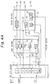
- the architecture of the line processor is illustrated in Fig. 4 and generally includes an SP interface block 1, a line block 2, a scan block 3, a line width block 4, a pattern block 5, an XP interface block 6 and a control block 7.
- the SP interface block 1 receives parameters that define the primitive to be created and also receives incoming address data.
- the parameters and address information are indicated respectively as inputs DT and ADDR to SP interface block 1.
- SP interface block 1 also produces data at its outputs for loading into respective registers of other blocks of the line processor.
- SP interface block 1 includes addressable registers X, Y, Z, Zx, Zy, W, H and CMD.
- the X and Y registers store the X and Y coordinates of the basic location data for the primitive to be generated.
- the Z register holds a primary Z value.
- the Zx and Zy registers respectively hold X-axis and Y-axis direction increments for the Z value, as will be discussed below.
- the W and H registers are for storing respective data indicative of the width and height of the primitive to be generated.
- the CMD register holds command data as a load signal that causes data to be stored in the other blocks of the line processor.
- Appropriate data DT received by SP interface block 1 are stored in accordance with address information ADDR in the respective registers. If the succeeding blocks are not occupied with generating a previous primitive when the command data is provided to SP interface block 1, then a load signal LD is provided to the succeeding blocks for loading of data, as will be described below. Data communication between SP interface block 1 and succeeding blocks is accompanied via a multiline connection labelled DATA in Fig. 4.
- the SP interface block 1 is inhibited from producing output data when the succeeding blocks are occupied with processing. At such times, SP interface block 1 produces a WAIT signal to a preceding-stage circuit in order to interrupt transmission of data to SP interface block 1 until the production of output data by block 1 is no longer inhibited. At that time, block 1 then produces output data and ceases to generate the WAIT signal.
- line block 2 creates a line or a polygonal contour on the basis of data received from SP interface block 1 by using algorithms such as Bresenham's algorithm.
- the interior of the polygon created by the line block 2 is scanned by scan block 3 in the X axis direction for the purpose of generating interpolated pixel data.
- Scan block 3 includes interpolation circuits for X-coordinate data, Y-coordinate data and R, G and B color data.
- line block 2 and scan block 3 include circuitry for adding a Z value to two-dimensional coordinate data.
- Line width block 4 adds a thickness to lines generated by line block 2 by adding appropriate data to pixels encircling X-Y coordinates provided by line block 2.
- Pattern block 5 adds attributes such as line patterns, hatch patterns, semi-transparent patterns, dither patterns, and so forth, to a primitive generated by the preceding blocks. More specifically, pattern block 5 has stored therein data for generating line patterns, hatch patterns, semitransparent patterns, and dither patterns, and refers to that data in order to generate for each pixel appropriate pixel data so that the desired pattern is created.
- XP interface block 6 supplies to a succeeding-stage circuit data DT for each pixel of the generated primitive.
- Control block 7 controls the operation of all of the other blocks of the line processor, and is connected to those blocks by control lines CTL.
- Circuitry for adding a Z value to two-dimensional coordinate data is shown in Fig. 5 and also in Fig. 4A.
- an address generator 51 is made up of an X register 11, and a Y counter 12, both of which are part of line block 2, as well as an X counter 31 that is part of scan block 3.
- X register 11 stores an initial X coordinate value that is received from SP interface block 1 via a terminal 21.
- X register 11 loads the initial X coordinate value into X counter 31, which, as each clock cycle occurs, increments the loaded value and outputs an incremented value via a terminal 41 as the X coordinate data for each pixel.
- Y counter 12 stores either an initial Y coordinate value received from SP interface block 1 via a terminal 22 or an incremented Y coordinate value. Y counter 12 outputs the stored Y coordinate value via a terminal 42.
- Color register 32 receives, pixel by pixel, color-related R, G and B data (hereinafter called "color data"), which is received through a terminal 23 and is output via a terminal 43.
- a Z value computing section 52 is made up of a first Z value computing subsection 13 which is part of line block 2 and a second Z value computing subsection 33 which is part of scan block 3.
- First Z value computing subsection 13 includes a register 14, an adder 15 and a register 16.
- Second Z value computing subsection 33 includes a register 35, an adder 36, a selector 37 and a register 38.
- Register 14 holds a value dZy corresponding to an amount by which the Z value is to be increased as processing proceeds in the Y axis direction. This amount will sometimes be referred to as the "Y-axis direction increment" for the Z value.
- Register 35 holds a value dZx corresponding to an amount by which the Z value is to be increased as processing proceeds in the X axis direction. This amount will sometimes be referred to as an "X-axis direction increment" for the Z value.
- Adder 15 is connected to receive the value stored in register 14 and also the value stored in register 16, and adds the two values together, supplying the sum for storage in register 16.
- Adder 36 is connected to receive the value stored in register 35 and also the value stored in register 38.
- Selector 37 selectively couples either register 16 or adder 36 to register 38. For each scan in the X axis direction by scan block 3, selector 37 couples register 16 to register 38 upon receipt of data for the first pixel in the scan and thereafter couples adder 36 to register 38 upon receipt of data for each subsequent pixel in the scan.
- X counter 31, terminal 42, color register 32 and selector 37 are respectively connected to X register 11, Y counter 12, terminal 23 and register 16 via a multi-line terminal A.
- Control block 7 provides clock signals via a control line CTL to X register 11, X counter 31, Y counter 12, color register 32, and registers 14, 16, 35 and 38. By other control lines (not separately shown) control block 7 provides hold signals to registers 16 and 38 for latching data therein. Count up signals are provided to X counter 31 and Y counter 13 by control block 7 via other control lines (not separately shown). Also, by another control line that is not separately shown control block 7 provides a load data signal to X counter 31.
- a Z value will be added to each pixel making up two-dimensional image data PT 1.
- the first scan begins with a pixel PX00 located at the bottom left corner of image data PT 1.
- the value X0 of the X coordinate of pixel PX00 is provided as an initial value by SP interface block 1 to X register 11 via terminal 21.
- the X coordinate value X0 is provided by register 11 t X counter 31, latched in X counter 31 in response to a signal received from control block 7, and output via terminal 41.
- SP interface block 1 also supplies Y coordinate value Y0 as an initial value to Y counter 12 via terminal 22.
- Y coordinate value Y0 is stored in Y counter 12 and output via terminal 42.
- SP interface block 1 provides color data for storage in color register 32 via terminal 23. Upon storage of the color data, it is output by color register 32 via terminal 43.
- An initial Z value Za is provided by SP interface block 1 via terminal 24 and loaded in register 16.
- the Y-axis direction increment dZy is loaded in register 14 via terminal 101 and the X-axis direction increment dZx is loaded in register 35 via terminal 100.
- data indicative of the height and width of the primitive to be generated is respectively loaded in register H of line block 2, and register W of scan block 3.
- register 16 is connected to register 38 via selector 37 for the first pixel in a scan
- the initial Z value Za is loaded from register 16 into register 38 and is output via terminal 44.
- the state of selector 37 is controlled by a signal provided by control block 7.
- X counter 31 increments the X coordinate value stored therein, and outputs the incremented X coordinate value X1 via terminal 41.
- the Y coordinate value Y0 is output via terminal 42.
- the color data received from SP interface block 1 via terminal 23 is stored in color register 32 and then output by color register 32 via terminal 43.
- an incremented X coordinate value Xi is provided via terminal 41 for each pixel of the first scan line, and the Y coordinate value Y0 is provided via terminal 42.
- the value YO is held constant in register 16 during the entire scan by a hold signal provided by control block 7.
- color data is provided via terminal 43 for each pixel, and a Z value Zx generated in the Z value computing section 52 is provided via terminal 44 for each pixel. All of these are provided to the succeeding-stage pattern block 5, as data for displaying the respective pixel.
- X coordinate value X0 representing the X coordinate of pixel PX01 is provided to X counter 31 by X register 11. That value is latched in X counter 31 and output via terminal 41.
- Y counter 12 increments the Y coordinate value Y0, so that a new Y coordinate value Y1 is output via terminal 42.
- Color data for the pixel PX01 is provided by SP interface block 1 via terminal 23 for storage in color register 32. Upon storage, the color data is output by color register 32 via terminal 43.
- selector 37 is controlled so that register 16 is coupled to register 38 with the result that the value Zy, referred to above, is stored in register 38, from where it is output as Z value Zx via terminal 44 and also is available for feedback to adder 36.
- the data for displaying pixel PX01 provided to pattern block 5 consists of X coordinate value X0, which is the initial value provided from X counter 31 via terminal 41, incremented Y coordinate value Y1 provided by Y counter 12 via terminal 42, color data provided via terminal 43, and Z value Zx provided by register 38 via terminal 44.
- color data, X coordinate and Y coordinate values, and a Z value Zx for each pixel PXi1 are provided in the same manner to pattern block 5.
- the Y coordinate value is Y1.
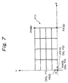
- Fig. 6 schematically illustrates conversion of two-dimensional image data into three-dimensional image data, according to the process described above.
- the coordinate values of pixel PX2 in two-dimensional space are expressed by (X, Y), and the Z value calculated for that pixel is represented by Z.
- a resulting 3-dimensional pixel PX3 is generated and may be represented by (X,Y,Z) with Z being calculated as noted above.
- color data for pixel PX2 is used as the color data for pixel PX3.
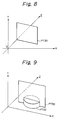
- the image data PT1 which is defined by 2-dimensional coordinates as shown in Fig. 7, can be considered as 3-dimensional image data PT30, for example, as shown in Fig. 8.
- the image data PT30 shown in Fig. 8 has the same appearance as one to which no Z value has been added.
- the combined image can be provided as shown in Fig. 9 on the basis of the respective Z values of image data PT30 and image data PT32.
- the data making up image PT30 can be stored in an image memory (not shown). Then the Z coordinate of each pixel of image data PT32 is compared with the Z coordinate of the corresponding pixel of PT30, and only the pixels of PT32 positioned ahead of the corresponding pixels of PT30 are stored in the image memory in place of the corresponding pixels of PT30.
- Z values generated by Z value computing section 52 can be added to all pixels of an image data that is defined in terms of 2-dimensional coordinates.
- any such image data can also be defined with pseudo 3-dimensional coordinates, which makes it possible to combine such an image data with three dimensional image data.
- Z value computing section 52 is rather simple in design and can easily add a Z value Zx to image data defined in 2 dimensions, with less computation, and in less time, than is required for calculation of such data by a software-controlled processor.
- the processing system described above generates Z values that have predetermined inclinations in the X axis and Y axis directions in an area defined in two dimensions, and that data is added by a Z axis coordinate value adding circuit to provide pseudo 3-dimensional image data on the basis of 2-dimensional image data. This is accomplished rapidly, and with a relatively small amount of computation.
Landscapes
- Physics & Mathematics (AREA)
- Engineering & Computer Science (AREA)
- Geometry (AREA)
- Computer Graphics (AREA)
- General Physics & Mathematics (AREA)
- Theoretical Computer Science (AREA)
- Image Generation (AREA)
- Digital Computer Display Output (AREA)
Abstract
Description
- This invention relates to image processing apparatus.
- An
arbitrary figure PT 10, as shown in Figs. 1 and 2 of the accompanying drawings, is represented by image data that consists of two-dimensional coordinates defined with respect to X and Y axes and that has no Z axis coordinate data. Such image data cannot easily be combined with image data defined by three-dimensional coordinates. - For example, Fig. 3 of the accompanying drawings schematically illustrates
image data PT 12 defined by two-dimensional coordinates andimage data PT 13 defined by three-dimensional coordinates. When it is intended to display together images represented both by thedata PT 12 and thedata PT 13, the data that can accurately be displayed in two dimensions is determined by the order in which the respectiveimage data PT 12 and PT 13 is written in memory. Accordingly, in order to combine image data defined by two-dimensional coordinates with image data defined by three-dimensional coordinates, it is necessary to add Z coordinate data to the image data defined by two-dimensional coordinates. - It has been proposed to calculate such Z coordinate data by means of a processor operating under software control and then to add the calculated Z coordinate data to the two-dimensional image data. However, such calculation of Z coordinate data requires an undesirably long period of time.
- In accordance with one aspect of the invention, there is provided an apparatus for processing image information that includes pixels each having X-axis and Y-axis coordinates. The apparatus includes a circuit for processing the image information in an X-axis direction, a circuit for processing the image information in a Y-axis direction and a circuit for adding a predetermined value representing a coordinate in a Z-axis direction to each pixel of the image information so that the image information is expressed in three dimensions.
- The foregoing apparatus provides for rapid calculation of the Z-axis coordinate data required to transform two-dimensional image data into pseudo three-dimensional image data.
- A preferred embodiment of the invention described below provides an image processing apparatus or system that can add a Z value to two-dimensional image data and so create a pseudo three-dimensional image with a relatively small amount of calculation and in a relatively short time.
- The invention will now be further described, by way of illustrative and non-limiting example, with reference to the accompanying drawings, in which
- Figs. 1 and 2 are schematic illustrations of image data defined by two-dimensional coordinates;
- Fig. 3 is a schematic illustration of image data defined by three-dimensional coordinates;
- Fig. 4 is a block diagram of a processing system or apparatus in accordance with an embodiment of the invention;
- Fig. 4A schematically illustrates some details of, and connections among, an interface block, a line block and a scan block that form part of the processing system of Fig. 4;
- Fig. 5 is a schematic circuit diagram showing portions of a line block, and a scan block that form part of the processing system of Fig. 4;
- Fig. 6 schematically shows conversion of two-dimensional image data into three-dimensional image data;
- Fig. 7 schematically shows processing of two-dimensional image data in X-axis and Y-axis directions;
- Fig. 8 schematically shows pseudo three-dimensional image data produced by adding Z values to two-dimensional image data; and
- Fig. 9 schematically shows a combination of an image defined by three-dimensional image data with an image defined by pseudo three-dimensional image data.
- An embodiment of the invention will now be described with reference to Figs. 4-9. The embodiment uses a line processor to create three-dimensional primitives. As used herein, the term "primitive" refers to a polygonal element that either directly images a polygon such as a triangle, rectangle, etc., or, alternatively, images a figure represented by such polygons.
- The line processor is capable of rapidly generating a two-dimensional or three-dimensional primitive. More specifically, upon receipt of processing parameters, the line processor outputs corresponding data at a rate of up to 25,000,000 pixels per second.
- The following are examples of primitives that may be generated by the line processor: two- or three-dimensional lines (i.e. straight lines), two- or three-dimensional triangles, two- or three-dimensional rectangles, other two- or three-dimensional polygons, a two-dimensional bit map, a two-dimensional pixel nap and a three-dimensional scan line pixel.
- Color data to be output by the line processor may include 24 bits of real color data, 10 bits of index color data, 3 or 4 bits of dither color data and 1 bit of XP color data.
- Also, the line processor may add attributes to the primitive such as a line pattern (represented by 32 bits), a hatch pattern (represented by 16 x 16 bits), a semi-transparent pattern (represented by 4 x 4 bits) and a line width (represented by 3 or 5 bits).
- The architecture of the line processor is illustrated in Fig. 4 and generally includes an
SP interface block 1, aline block 2, ascan block 3, aline width block 4, apattern block 5, anXP interface block 6 and acontrol block 7. - The
SP interface block 1 receives parameters that define the primitive to be created and also receives incoming address data. The parameters and address information are indicated respectively as inputs DT and ADDR toSP interface block 1.SP interface block 1 also produces data at its outputs for loading into respective registers of other blocks of the line processor. - Referring also now to Fig. 4A,
SP interface block 1 includes addressable registers X, Y, Z, Zx, Zy, W, H and CMD. The X and Y registers store the X and Y coordinates of the basic location data for the primitive to be generated. The Z register holds a primary Z value. The Zx and Zy registers respectively hold X-axis and Y-axis direction increments for the Z value, as will be discussed below. The W and H registers are for storing respective data indicative of the width and height of the primitive to be generated. The CMD register holds command data as a load signal that causes data to be stored in the other blocks of the line processor. - Appropriate data DT received by
SP interface block 1 are stored in accordance with address information ADDR in the respective registers. If the succeeding blocks are not occupied with generating a previous primitive when the command data is provided toSP interface block 1, then a load signal LD is provided to the succeeding blocks for loading of data, as will be described below. Data communication betweenSP interface block 1 and succeeding blocks is accompanied via a multiline connection labelled DATA in Fig. 4. - The
SP interface block 1 is inhibited from producing output data when the succeeding blocks are occupied with processing. At such times,SP interface block 1 produces a WAIT signal to a preceding-stage circuit in order to interrupt transmission of data toSP interface block 1 until the production of output data byblock 1 is no longer inhibited. At that time,block 1 then produces output data and ceases to generate the WAIT signal. - Referring again to Fig. 4,
line block 2 creates a line or a polygonal contour on the basis of data received fromSP interface block 1 by using algorithms such as Bresenham's algorithm. The interior of the polygon created by theline block 2 is scanned byscan block 3 in the X axis direction for the purpose of generating interpolated pixel data.Scan block 3 includes interpolation circuits for X-coordinate data, Y-coordinate data and R, G and B color data. - As will be described in more detail below,
line block 2 andscan block 3 include circuitry for adding a Z value to two-dimensional coordinate data. -
Line width block 4 adds a thickness to lines generated byline block 2 by adding appropriate data to pixels encircling X-Y coordinates provided byline block 2. -
Pattern block 5 adds attributes such as line patterns, hatch patterns, semi-transparent patterns, dither patterns, and so forth, to a primitive generated by the preceding blocks. More specifically,pattern block 5 has stored therein data for generating line patterns, hatch patterns, semitransparent patterns, and dither patterns, and refers to that data in order to generate for each pixel appropriate pixel data so that the desired pattern is created. - XP
interface block 6 supplies to a succeeding-stage circuit data DT for each pixel of the generated primitive. -
Control block 7 controls the operation of all of the other blocks of the line processor, and is connected to those blocks by control lines CTL. - Circuitry for adding a Z value to two-dimensional coordinate data is shown in Fig. 5 and also in Fig. 4A.
- In the circuit of Fig. 5, an
address generator 51 is made up of anX register 11, and aY counter 12, both of which are part ofline block 2, as well as anX counter 31 that is part ofscan block 3. - X register 11 stores an initial X coordinate value that is received from
SP interface block 1 via aterminal 21. X register 11 loads the initial X coordinate value intoX counter 31, which, as each clock cycle occurs, increments the loaded value and outputs an incremented value via aterminal 41 as the X coordinate data for each pixel. - Y counter 12 stores either an initial Y coordinate value received from
SP interface block 1 via aterminal 22 or an incremented Y coordinate value. Y counter 12 outputs the stored Y coordinate value via aterminal 42. -
Color register 32 receives, pixel by pixel, color-related R, G and B data (hereinafter called "color data"), which is received through a terminal 23 and is output via aterminal 43. - In the circuit of Fig. 5, a Z
value computing section 52 is made up of a first Zvalue computing subsection 13 which is part ofline block 2 and a second Zvalue computing subsection 33 which is part ofscan block 3. First Zvalue computing subsection 13 includes aregister 14, anadder 15 and aregister 16. Second Zvalue computing subsection 33 includes aregister 35, anadder 36, aselector 37 and aregister 38. -
Register 14 holds a value dZy corresponding to an amount by which the Z value is to be increased as processing proceeds in the Y axis direction. This amount will sometimes be referred to as the "Y-axis direction increment" for the Z value.Register 35 holds a value dZx corresponding to an amount by which the Z value is to be increased as processing proceeds in the X axis direction. This amount will sometimes be referred to as an "X-axis direction increment" for the Z value. -
Adder 15 is connected to receive the value stored inregister 14 and also the value stored inregister 16, and adds the two values together, supplying the sum for storage inregister 16.Adder 36 is connected to receive the value stored inregister 35 and also the value stored inregister 38.Selector 37 selectively couples either register 16 oradder 36 to register 38. For each scan in the X axis direction byscan block 3,selector 37 couples register 16 to register 38 upon receipt of data for the first pixel in the scan and thereafter couples adder 36 to register 38 upon receipt of data for each subsequent pixel in the scan. -
X counter 31,terminal 42,color register 32 andselector 37 are respectively connected to X register 11,Y counter 12,terminal 23 and register 16 via a multi-line terminal A. -
Control block 7 provides clock signals via a control line CTL to X register 11,X counter 31,Y counter 12,color register 32, and registers 14, 16, 35 and 38. By other control lines (not separately shown)control block 7 provides hold signals toregisters X counter 31 and Y counter 13 bycontrol block 7 via other control lines (not separately shown). Also, by another control line that is not separately showncontrol block 7 provides a load data signal toX counter 31. - Operation of the system will now be explained with reference to Fig. 7-9. In particular, referring initially to Fig. 7, a Z value will be added to each pixel making up two-dimensional
image data PT 1. - It will be assumed that the first scan begins with a pixel PX00 located at the bottom left corner of
image data PT 1. Thus the value X0 of the X coordinate of pixel PX00 is provided as an initial value bySP interface block 1 to X register 11 viaterminal 21. - The X coordinate value X0 is provided by register 11
t X counter 31, latched inX counter 31 in response to a signal received fromcontrol block 7, and output viaterminal 41. -
SP interface block 1 also supplies Y coordinate value Y0 as an initial value to Y counter 12 viaterminal 22. Y coordinate value Y0 is stored inY counter 12 and output viaterminal 42. -
SP interface block 1 provides color data for storage incolor register 32 viaterminal 23. Upon storage of the color data, it is output bycolor register 32 viaterminal 43. - An initial Z value Za is provided by
SP interface block 1 viaterminal 24 and loaded inregister 16. At the same time, the Y-axis direction increment dZy is loaded inregister 14 viaterminal 101 and the X-axis direction increment dZx is loaded inregister 35 viaterminal 100. - Also, data indicative of the height and width of the primitive to be generated is respectively loaded in register H of
line block 2, and register W ofscan block 3. - Since, as noted above, register 16 is connected to register 38 via
selector 37 for the first pixel in a scan, the initial Z value Za is loaded fromregister 16 intoregister 38 and is output viaterminal 44. The state ofselector 37 is controlled by a signal provided bycontrol block 7. - With the output of the color data via
terminal 43 as mentioned above, it will be appreciated that an X coordinate value X0, a Y coordinate value Y0, and a Z value
- Upon application of a clock signal supplied by
control block 7, X counter 31 increments the X coordinate value stored therein, and outputs the incremented X coordinate value X1 viaterminal 41. At the same time, the Y coordinate value Y0 is output viaterminal 42. - Upon application of the same clock signal, the color data received from
SP interface block 1 viaterminal 23 is stored incolor register 32 and then output bycolor register 32 viaterminal 43. - Also upon application of the clock signal, the state of
selector 37 is changed so thatadder 36 is coupled to register 38 andadder 36 adds the initial value Za stored inregister 38 and the X-axis direction increment dZx stored inregister 35 and outputs the resulting sum
selector 37 for storage inregister 38. That resulting Z value Zx is accordingly output viaterminal 44 and is also available for feedback to adder 36. - It will be appreciated, then, that the incremented X coordinate value X1 provided by
X counter 31 viaterminal 41, the Y coordinate value Y0 provided as an initial value from Y counter 12 viaterminal 42, color data viaterminal 43, and the Z value Zx provided fromregister 38 are supplied, respectively, to pattern block 5 as data for displayingpixel 10. - In this fashion, with timing controlled by the aforesaid clock signal, an incremented X coordinate value Xi is provided via
terminal 41 for each pixel of the first scan line, and the Y coordinate value Y0 is provided viaterminal 42. (The value YO is held constant inregister 16 during the entire scan by a hold signal provided bycontrol block 7.) In addition, with the same timing, color data is provided viaterminal 43 for each pixel, and a Z value Zx generated in the Zvalue computing section 52 is provided viaterminal 44 for each pixel. All of these are provided to the succeeding-stage pattern block 5, as data for displaying the respective pixel. - Referring again to the image data PT1 shown in Fig. 7, when the count value in
X counter 31 reaches "N" (which corresponds to the width data stored in register W of scan block 3) and corresponding color data, X and Y coordinate values, and the Z value Zx are provided for pixel PXN0, the line scan in the X axis direction is completed. Pixel PX01 shown in Fig. 7 then becomes the start point for the next line scan. - As before, X coordinate value X0 representing the X coordinate of pixel PX01 is provided to
X counter 31 byX register 11. That value is latched inX counter 31 and output viaterminal 41. - At the same time, Y counter 12 increments the Y coordinate value Y0, so that a new Y coordinate value Y1 is output via
terminal 42. Color data for the pixel PX01 is provided bySP interface block 1 viaterminal 23 for storage incolor register 32. Upon storage, the color data is output bycolor register 32 viaterminal 43. - Also at this time, in first Z
value computing subsection 13, the initial value Za stored inregister 16 and the Y-axis direction increment dZy stored inregister 14 are added byadder 15 and the resulting sum
register 16 where it is available for feedback to adder 15 on the next cycle. - In addition, the state of
selector 37 is controlled so thatregister 16 is coupled to register 38 with the result that the value Zy, referred to above, is stored inregister 38, from where it is output as Z value Zx viaterminal 44 and also is available for feedback to adder 36. - As was discussed in connection with the previous line scan, for the processing of the next pixel, the state of
selector 37 is controlled so thatadder 36 will be coupled to provide its output to register 38. - Accordingly, the data for displaying pixel PX01 provided to pattern block 5 consists of X coordinate value X0, which is the initial value provided from X counter 31 via
terminal 41, incremented Y coordinate value Y1 provided byY counter 12 viaterminal 42, color data provided viaterminal 43, and Z value Zx provided byregister 38 viaterminal 44. - Thereafter, color data, X coordinate and Y coordinate values, and a Z value Zx for each pixel PXi1 are provided in the same manner to
pattern block 5. In each case the Y coordinate value is Y1. - Fig. 6 schematically illustrates conversion of two-dimensional image data into three-dimensional image data, according to the process described above. The coordinate values of pixel PX2 in two-dimensional space are expressed by (X, Y), and the Z value calculated for that pixel is represented by Z. As will be understood from the procedure described above, that Z value is calculated according to the following formula:

- Accordingly, a resulting 3-dimensional pixel PX3 is generated and may be represented by (X,Y,Z) with Z being calculated as noted above.
- It should be understood that the color data for pixel PX2 is used as the color data for pixel PX3.
- Referring again to Fig. 7, the procedure described above for providing color data, X coordinate and Y coordinate values, and a Z value for each pixel PXij is carried out successively from pixel PX00 through pixel PXNM in the image data PT1, where M corresponds to the height data stored in register H of
line block 2. Accordingly, a Z value Zx generated by Zvalue computing section 52 is added to each of the pixels PX00 through PXNM which form the image data PT1. - Further, since a Z value Zx is added to each pixel PXij, the image data PT1 which is defined by 2-dimensional coordinates as shown in Fig. 7, can be considered as 3-dimensional image data PT30, for example, as shown in Fig. 8.
- The image data PT30 shown in Fig. 8 has the same appearance as one to which no Z value has been added. However, when pseudo 3-dimensional image data PT30, and a 3-dimensional image data PT32 are combined, the combined image can be provided as shown in Fig. 9 on the basis of the respective Z values of image data PT30 and image data PT32. For example, the data making up image PT30 can be stored in an image memory (not shown). Then the Z coordinate of each pixel of image data PT32 is compared with the Z coordinate of the corresponding pixel of PT30, and only the pixels of PT32 positioned ahead of the corresponding pixels of PT30 are stored in the image memory in place of the corresponding pixels of PT30.
- According to the embodiment as described above, Z values generated by Z
value computing section 52 can be added to all pixels of an image data that is defined in terms of 2-dimensional coordinates. Thus, any such image data can also be defined with pseudo 3-dimensional coordinates, which makes it possible to combine such an image data with three dimensional image data. - It will appreciated that Z
value computing section 52 is rather simple in design and can easily add a Z value Zx to image data defined in 2 dimensions, with less computation, and in less time, than is required for calculation of such data by a software-controlled processor. - Further, the processing system described above generates Z values that have predetermined inclinations in the X axis and Y axis directions in an area defined in two dimensions, and that data is added by a Z axis coordinate value adding circuit to provide pseudo 3-dimensional image data on the basis of 2-dimensional image data. This is accomplished rapidly, and with a relatively small amount of computation.
Claims (6)
- An image processing apparatus comprising:a generator unit (1, 2) for generating a primitive as a polygonal image element, said primitive initially consisting of two-dimensional image information that includes pixels each having X-axis and Y-axis coordinates;a colour information adding unit (32) for providing colour information to said primitive; anda Z-value coordinate data adding circuit (13) for adding a predetermined value (Z) representing a coordinate in a Z-axis direction to each said pixel of said image information so that said primitive is expressed in three dimension.
- An image processing apparatus according to claim 1, wherein said primitive expressed in three dimensions is expressed as pixels each including X coordinate data, Y coordinate data, colour data, and Z-value data.
- An image processing apparatus according to claim 1 or 2, further including a Z-value computing circuit comprising:a register (38) for holding an initial Z value (Z);a register (35) for holding an X-axis (dZx) direction increment for said Z value; anda register (14) for holding a Y-axis direction increment (dZy) for said Z value.
- An image processing apparatus according to claim 3, wherein said Z-value computing circuit computes said predetermined value to be added to said pixel on the basis of said X-axis direction increment and said Y-axis direction increment.
- An image processing apparatus according to claim 1, 2, 3 or 4, wherein said Z-value coordinate data adding circuit adds to said primitive Z values having predetermined inclinations in said X-axis direction and said Y-axis direction.
- An image processing apparatus according to claim 1, 2, 3, 4 or 5, further comprising an attribute adding unit (5) for adding a predetermined attribute to said primitive.
Applications Claiming Priority (3)
| Application Number | Priority Date | Filing Date | Title |
|---|---|---|---|
| JP276529/91 | 1991-09-27 | ||
| JP3276529A JPH0589253A (en) | 1991-09-27 | 1991-09-27 | Image drawing device |
| EP92308788A EP0535879B1 (en) | 1991-09-27 | 1992-09-25 | Image processing apparatus and method |
Related Parent Applications (2)
| Application Number | Title | Priority Date | Filing Date |
|---|---|---|---|
| EP92308788A Division EP0535879B1 (en) | 1991-09-27 | 1992-09-25 | Image processing apparatus and method |
| EP92308788.6 Division | 1992-09-25 |
Publications (2)
| Publication Number | Publication Date |
|---|---|
| EP0798666A2 true EP0798666A2 (en) | 1997-10-01 |
| EP0798666A3 EP0798666A3 (en) | 1997-12-29 |
Family
ID=17570748
Family Applications (2)
| Application Number | Title | Priority Date | Filing Date |
|---|---|---|---|
| EP97201780A Withdrawn EP0798666A3 (en) | 1991-09-27 | 1992-09-25 | Image processing apparatus |
| EP92308788A Expired - Lifetime EP0535879B1 (en) | 1991-09-27 | 1992-09-25 | Image processing apparatus and method |
Family Applications After (1)
| Application Number | Title | Priority Date | Filing Date |
|---|---|---|---|
| EP92308788A Expired - Lifetime EP0535879B1 (en) | 1991-09-27 | 1992-09-25 | Image processing apparatus and method |
Country Status (4)
| Country | Link |
|---|---|
| US (1) | US5502798A (en) |
| EP (2) | EP0798666A3 (en) |
| JP (1) | JPH0589253A (en) |
| DE (1) | DE69230363T2 (en) |
Cited By (1)
| Publication number | Priority date | Publication date | Assignee | Title |
|---|---|---|---|---|
| WO1999003068A1 (en) * | 1997-07-07 | 1999-01-21 | Reveo, Inc. | Method and apparatus for monoscopic to stereoscopic image conversion |
Families Citing this family (9)
| Publication number | Priority date | Publication date | Assignee | Title |
|---|---|---|---|---|
| US5854631A (en) * | 1995-11-22 | 1998-12-29 | Silicon Graphics, Inc. | System and method for merging pixel fragments based on depth range values |
| EP0809913B1 (en) * | 1995-12-19 | 2002-06-12 | Koninklijke Philips Electronics N.V. | Parallactic depth-dependent pixel shifts |
| US6784885B1 (en) * | 1996-10-10 | 2004-08-31 | Samsung Electronics Co., Ltd. | Method and apparatus for three-dimensional parallax drawing |
| US20030158786A1 (en) * | 1999-02-26 | 2003-08-21 | Skyline Software Systems, Inc. | Sending three-dimensional images over a network |
| US6457034B1 (en) * | 1999-11-02 | 2002-09-24 | Ati International Srl | Method and apparatus for accumulation buffering in the video graphics system |
| JP2002133438A (en) | 2000-10-19 | 2002-05-10 | Mitsubishi Electric Corp | Three-dimensional graphics drawing device, three-dimensional graphics drawing method, and computer-readable recording medium recording three-dimensional polygon data |
| US6720961B2 (en) | 2000-11-06 | 2004-04-13 | Thomas M. Tracy | Method and apparatus for displaying an image in three dimensions |
| US9652516B1 (en) | 2008-03-07 | 2017-05-16 | Birst, Inc. | Constructing reports using metric-attribute combinations |
| JP5661134B2 (en) * | 2013-03-12 | 2015-01-28 | 株式会社Takumi | Image processing apparatus and image processing method |
Family Cites Families (4)
| Publication number | Priority date | Publication date | Assignee | Title |
|---|---|---|---|---|
| US4925294A (en) * | 1986-12-17 | 1990-05-15 | Geshwind David M | Method to convert two dimensional motion pictures for three-dimensional systems |
| US4697178A (en) * | 1984-06-29 | 1987-09-29 | Megatek Corporation | Computer graphics system for real-time calculation and display of the perspective view of three-dimensional scenes |
| GB2210540A (en) * | 1987-09-30 | 1989-06-07 | Philips Electronic Associated | Method of and arrangement for modifying stored data,and method of and arrangement for generating two-dimensional images |
| US5144291A (en) * | 1987-11-02 | 1992-09-01 | Matsushita Electric Industrial Co., Ltd. | Means for eliminating hidden surface |
-
1991
- 1991-09-27 JP JP3276529A patent/JPH0589253A/en active Pending
-
1992
- 1992-09-25 EP EP97201780A patent/EP0798666A3/en not_active Withdrawn
- 1992-09-25 DE DE69230363T patent/DE69230363T2/en not_active Expired - Fee Related
- 1992-09-25 EP EP92308788A patent/EP0535879B1/en not_active Expired - Lifetime
-
1994
- 1994-09-26 US US08/311,907 patent/US5502798A/en not_active Expired - Fee Related
Cited By (3)
| Publication number | Priority date | Publication date | Assignee | Title |
|---|---|---|---|---|
| WO1999003068A1 (en) * | 1997-07-07 | 1999-01-21 | Reveo, Inc. | Method and apparatus for monoscopic to stereoscopic image conversion |
| US6031564A (en) * | 1997-07-07 | 2000-02-29 | Reveo, Inc. | Method and apparatus for monoscopic to stereoscopic image conversion |
| US6215516B1 (en) | 1997-07-07 | 2001-04-10 | Reveo, Inc. | Method and apparatus for monoscopic to stereoscopic image conversion |
Also Published As
| Publication number | Publication date |
|---|---|
| EP0535879B1 (en) | 1999-12-01 |
| EP0535879A3 (en) | 1994-01-05 |
| EP0798666A3 (en) | 1997-12-29 |
| DE69230363D1 (en) | 2000-01-05 |
| EP0535879A2 (en) | 1993-04-07 |
| DE69230363T2 (en) | 2000-06-29 |
| JPH0589253A (en) | 1993-04-09 |
| US5502798A (en) | 1996-03-26 |
Similar Documents
| Publication | Publication Date | Title |
|---|---|---|
| KR0156052B1 (en) | Texture mapping method and device | |
| US6172678B1 (en) | Image processing method and apparatus including hidden surface removal | |
| US4935879A (en) | Texture mapping apparatus and method | |
| JP3107452B2 (en) | Texture mapping method and apparatus | |
| US4812988A (en) | Processor for the elimination of concealed faces for the synthesis of images in three dimensions | |
| US5877769A (en) | Image processing apparatus and method | |
| EP0329101B1 (en) | Three-dimensional graphic processing apparatus | |
| US5029225A (en) | Texture mapping apparatus | |
| US6184893B1 (en) | Method and system for filtering texture map data for improved image quality in a graphics computer system | |
| EP0798666A2 (en) | Image processing apparatus | |
| US5373568A (en) | Apparatus for image transformation | |
| EP0416421B1 (en) | A clipping processor | |
| US5467409A (en) | Method for determining a surface to be hidden and image transforming apparatus | |
| US5317519A (en) | Machining stimulation system | |
| JP2951663B2 (en) | Texture mapping apparatus and method | |
| US6563497B1 (en) | Image processing apparatus | |
| US5377316A (en) | Line image generating apparatus | |
| JP3556517B2 (en) | 3D image processing device | |
| US5864344A (en) | Computer graphics circuit | |
| JPH0345427B2 (en) | ||
| JPH10222690A (en) | Three-dimensional image generation method and apparatus, and three-dimensional image processing apparatus using the method and apparatus | |
| EP0364243A2 (en) | Three-dimensional geometry processing method and apparatus therefor | |
| JP2668863B2 (en) | Cross-section drawing device | |
| KR0176495B1 (en) | Texel mapping accelerator | |
| KR19980026639A (en) | 3-D graphics controller |
Legal Events
| Date | Code | Title | Description |
|---|---|---|---|
| PUAI | Public reference made under article 153(3) epc to a published international application that has entered the european phase |
Free format text: ORIGINAL CODE: 0009012 |
|
| AC | Divisional application: reference to earlier application |
Ref document number: 535879 Country of ref document: EP |
|
| AK | Designated contracting states |
Kind code of ref document: A2 Designated state(s): DE FR GB |
|
| PUAL | Search report despatched |
Free format text: ORIGINAL CODE: 0009013 |
|
| AK | Designated contracting states |
Kind code of ref document: A3 Designated state(s): DE FR GB |
|
| 17P | Request for examination filed |
Effective date: 19980512 |
|
| 17Q | First examination report despatched |
Effective date: 19981211 |
|
| STAA | Information on the status of an ep patent application or granted ep patent |
Free format text: STATUS: THE APPLICATION IS DEEMED TO BE WITHDRAWN |
|
| 18D | Application deemed to be withdrawn |
Effective date: 19990422 |