EP0798658A1 - Device for information transfer between a portable object and a reader - Google Patents
Device for information transfer between a portable object and a reader Download PDFInfo
- Publication number
- EP0798658A1 EP0798658A1 EP97400663A EP97400663A EP0798658A1 EP 0798658 A1 EP0798658 A1 EP 0798658A1 EP 97400663 A EP97400663 A EP 97400663A EP 97400663 A EP97400663 A EP 97400663A EP 0798658 A1 EP0798658 A1 EP 0798658A1
- Authority
- EP
- European Patent Office
- Prior art keywords
- reader
- portable object
- substrate
- antenna
- mark
- Prior art date
- Legal status (The legal status is an assumption and is not a legal conclusion. Google has not performed a legal analysis and makes no representation as to the accuracy of the status listed.)
- Withdrawn
Links
Images

Classifications
-
- G—PHYSICS
- G06—COMPUTING; CALCULATING OR COUNTING
- G06K—GRAPHICAL DATA READING; PRESENTATION OF DATA; RECORD CARRIERS; HANDLING RECORD CARRIERS
- G06K7/00—Methods or arrangements for sensing record carriers, e.g. for reading patterns
- G06K7/10—Methods or arrangements for sensing record carriers, e.g. for reading patterns by electromagnetic radiation, e.g. optical sensing; by corpuscular radiation
- G06K7/10009—Methods or arrangements for sensing record carriers, e.g. for reading patterns by electromagnetic radiation, e.g. optical sensing; by corpuscular radiation sensing by radiation using wavelengths larger than 0.1 mm, e.g. radio-waves or microwaves
- G06K7/10316—Methods or arrangements for sensing record carriers, e.g. for reading patterns by electromagnetic radiation, e.g. optical sensing; by corpuscular radiation sensing by radiation using wavelengths larger than 0.1 mm, e.g. radio-waves or microwaves using at least one antenna particularly designed for interrogating the wireless record carriers
- G06K7/10336—Methods or arrangements for sensing record carriers, e.g. for reading patterns by electromagnetic radiation, e.g. optical sensing; by corpuscular radiation sensing by radiation using wavelengths larger than 0.1 mm, e.g. radio-waves or microwaves using at least one antenna particularly designed for interrogating the wireless record carriers the antenna being of the near field type, inductive coil
-
- G—PHYSICS
- G07—CHECKING-DEVICES
- G07B—TICKET-ISSUING APPARATUS; FARE-REGISTERING APPARATUS; FRANKING APPARATUS
- G07B15/00—Arrangements or apparatus for collecting fares, tolls or entrance fees at one or more control points
- G07B15/02—Arrangements or apparatus for collecting fares, tolls or entrance fees at one or more control points taking into account a variable factor such as distance or time, e.g. for passenger transport, parking systems or car rental systems
Definitions
- the present invention relates to a transfer device between a portable object and a reader.
- the invention finds a particularly advantageous application in the field of transport, said portable object then being a single journey ticket or a return ticket.
- Another field of application of the invention is that of access control, the portable object being in this case a badge for unique access to certain premises.
- the electronic component of the card is connected to a first antenna configured on the substrate, while the reader comprises a second antenna, so that, when the card is approached from the reader of the terminal, the inductive coupling between the first and second antennas are established, thus allowing electronic transfer of information, without any electrical contact between the component and the reader.
- Information concerning, for example, the number of journeys still available on a given journey is stored in a non-volatile memory of the component and is liable to be modified by the reader when the card is presented in the vicinity of the terminal.
- the technical problem to be solved by the object of the present invention is to propose a device for electronic transfer of information between, on the one hand, an electronic component placed on a substrate of a portable object, substrate on which is also consisting of a first antenna connected to said component, and, on the other hand, a reader comprising a second antenna, said electronic transfer of information being effected by inductive coupling between said first and second antennas, without electrical contact between the component and the reader , a device which made it possible, in the case in particular of portable objects made up of transport tickets for limited use, to identify blank tickets and tickets already used.
- the solution to the technical problem posed consists, according to the present invention, in that said reader comprises a marking means capable of inscribing a mark on said substrate when the portable object is placed in the immediate vicinity of the reader.
- the portable object is marked when it is presented the first time at a distance very close, less than a few millimeters, from the reader with the advantage for the user of being protected, by the portable object itself.
- harmful effects of the marking means which, as will be seen in detail below, may be, for example, laser radiation, ultraviolet flash or else an inkjet, an infrared device, and, more generally, any physical marking system.
- the mark registered in this way will indicate to the user that the portable object, simple use ticket for example, has already been presented to a reader.
- the proximity of the portable object and the reader also has the advantage of allowing proper marking.
- said reader comprises means for controlling said marking means, capable of triggering the registration of said mark on the substrate of the portable object during the electronic transfer of information.
- said first antenna coupled to the electronic component has a minimum quality factor allowing electronic transfer of information only in the event of immediate proximity of the portable object relative to the reader.
- the antenna being a constituent entering for a significant part in the cost of the portable object, one thus obtains a significant reduction of the cost price, for example by using antennas simply serigraphed on the substrate.
- the price of this type of antenna is linked to the silver or copper density of the inks used and therefore directly to the price of the ink.
- said electronic component of the portable object comprises means for measuring signal level in said first antenna and means for comparing said level with a reference value stored in a non-volatile memory of the component, electronic transfer of information only possible if the measured level is at least equal to said reference value.
- Figure 1 is a schematic perspective view of an electronic information transfer device according to the invention.
- FIG. 2 is a diagram showing means for controlling the marking means of the device in FIG. 1.
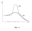
- FIG. 3 is a diagram representing, as a function of the frequency f, the factor Q1 of degraded quality of the antenna of the portable object shown in FIG. 1 and the factor Q2 of quality of an antenna of a portable object to large inductive coupling range.
- FIG 1 is shown schematically an electronic information transfer device between an electronic component 12 of a portable object 10 and a reader 20.
- said portable object 10 can be a ticket limited use transportation or single access badge.
- the reader 20 is generally incorporated into a fixed payment or identification terminal.
- the electronic component 12 is, for example, a semiconductor chip, or chip, comprising at least one non-volatile memory in which information is stored which must be transmitted to or from the reader 20.
- the component 12 is placed on the substrate 13 portable object 10, which may be made of plastic or, better because cheaper, cardboard.
- the substrate 13 portable object 10 which may be made of plastic or, better because cheaper, cardboard.
- Various modes of integration of the component 12 with the substrate 13 can be envisaged, in particular the insertion of the component in a cavity arranged in the substrate, in the manner of ISO electronic memory cards, widely used today.
- the substrate 13 also carries a first antenna 11 connected to the component 12.
- the antenna 11 is screen printed on the substrate 13 or also produced by metallization transfers, for example deposition aluminum on Mylar (registered trademark), these techniques being much less expensive than those used to obtain antennas with high quality factor, involving conductors with low resistivity and large diameter or thickness.
- the reader 20 comprises a second antenna 21 shown in a rectangular shape in FIG. 1 but which could just as easily be a circular loop, the electronic transfer of information taking place by inductive coupling between the first 11 and second 21 antennas when the portable object 10 is brought, in a movement substantially parallel to the arrow F1, in the vicinity very close to the reader 20, in the position shown in dotted lines.
- the reader 20 comprises, in a central region of the second antenna 21, a marking means 22 capable of inscribing a mark in an area 14 of the substrate 13 when, precisely, the portable object 10 is placed in the immediate vicinity of the reader 20 in the dotted position in FIG. 1.
- two operations are carried out in the same approach movement of the portable object 10, namely the achievement of sufficient inductive coupling between the two antennas 11, 21 and the marking of the substrate, suitable for enabling the user to identify portable objects already in use.
- said marking means 22 is a laser capable of writing said mark on the substrate 13 of the portable object 10, directly in the area 14 of the substrate itself.
- the marking zone 14 is heat-sensitive, such as a deposit of ink or of heat-sensitive resin.
- the reduction in laser energy in addition to reducing the consumption and the price of the laser, also makes it possible to eliminate the risks for the user.
- the advantage of the laser is that it allows a mark to be registered in the form of alpha-numeric characters.
- said marking means is a flash capable of inscribing said mark on an area 14 of the substrate 13 on which an ink is deposited photosensitive.
- the registered mark appears in the form of a zone of color different from that of the substrate, without the possibility of writing alpha-numeric characters.
- said marking means is constituted by the second antenna 21 itself, capable of inscribing said mark by demagnetization, when the portable object 10 is moved away from the reader 20 according to arrow F2 in FIG. 1, of a magnetosensitive material, such as ferrofluid, deposited on the substrate 13.
- a magnetosensitive material such as ferrofluid
- the second antenna 21 is connected to a processing unit 23 which makes it possible to receive the information transmitted by the electronic component 12, to process said information and to transmit back to the component 12 the information thus processed.
- the first antenna 11 coupled to the electronic component 12 may have a Q 1 factor of degraded quality, allowing electronic transfer of information only in the event of immediate proximity of the portable object 10 relative to the reader 20.
- the poor performance of the antenna 11 is compensated by a strong inductive coupling between the two antennas 11, 21 due to their very close distance.
- degraded is meant a quality factor lower than the quality factor Q2 that the antenna 11 should have in a use where the portable object 10 would not approach less than a few centimeters from the reader 20.
- FIG. 3 representing the quality factors Q1 and Q2 as a function of the frequency.
- the electronic component 12 of the portable object 10 includes means for measuring the signal level in the antenna 11. The level thus measured is then applied to means of comparison with a reference value representing the minimum level of the signal in the antenna 11 to be reached so that the transfer can be carried out. If the measured level is at least equal to said reference value, the transfer will be authorized; otherwise, it will be prohibited.
- This reference level will be achieved for example using a voltage source. Exceeding, even fleetingly, this level will trigger electronic transfer. During the transfer or at the end, the marking will be carried out.
Abstract
Description
La présente invention concerne un dispositif de transfert entre un objet portable et un lecteur.The present invention relates to a transfer device between a portable object and a reader.
L'invention trouve une application particulièrement avantageuse dans le domaine du transport, ledit objet portable étant alors un ticket de trajet unique ou un ticket aller-retour. Un autre domaine d'application de l'invention est celui du contrôle d'accès, l'objet portable étant dans ce cas un badge d'accès unique à certains locaux.The invention finds a particularly advantageous application in the field of transport, said portable object then being a single journey ticket or a return ticket. Another field of application of the invention is that of access control, the portable object being in this case a badge for unique access to certain premises.
On connaît de l'état de la technique, notamment dans le domaine du transport, des dispositifs, souvent appelés "cartes sans contact", qui permettent d'effectuer des transferts électroniques d'informations entre, d'une part, un composant électronique disposé sur le substrat d'une carte au format ISO, constituant l'objet portable, et, d'autre part, un lecteur installé dans une borne de paiement placée sur le chemin d'accès au moyen de transport considéré.There are known from the state of the art, in particular in the field of transport, devices, often called "contactless cards", which make it possible to carry out electronic transfers of information between, on the one hand, an electronic component disposed on the substrate of an ISO format card, constituting the portable object, and, on the other hand, a reader installed in a payment terminal placed on the path to the means of transport considered.
Le composant électronique de la carte est relié à une première antenne configurée sur le substrat, tandis que le lecteur comporte une deuxième antenne, de telle sorte que, lorsque la carte est approchée du lecteur de la borne, le couplage inductif entre les première et deuxième antennes s'établisse, permettant ainsi le transfert électronique d'informations, sans aucun contact électrique entre le composant et le lecteur.The electronic component of the card is connected to a first antenna configured on the substrate, while the reader comprises a second antenna, so that, when the card is approached from the reader of the terminal, the inductive coupling between the first and second antennas are established, thus allowing electronic transfer of information, without any electrical contact between the component and the reader.
Des informations concernant, par exemple, le nombre de trajets encore disponibles sur un parcours donné, sont stockées dans une mémoire non volatile du composant et sont susceptibles d'être modifiées par le lecteur lorsque la carte est présentée au voisinage de la borne.Information concerning, for example, the number of journeys still available on a given journey, is stored in a non-volatile memory of the component and is liable to be modified by the reader when the card is presented in the vicinity of the terminal.
Bien entendu, le transfert d'informations devant pouvoir s'effectuer mains libres sur des portées de l'ordre de 10 cm, les divers constituants de ces dispositifs sans contact, à savoir essentiellement les deux antennes, doivent être dimensionnées en conséquence, et sont de ce fait relativement onéreux. C'est pourquoi ce type de technologie est actuellement réservée aux cartes multiusage, comme les cartes de transport à abonnement, dont la validité expire à date fixe, par exemple mensuellement.Of course, since the transfer of information must be able to be carried out hands-free over ranges of the order of 10 cm, the various components of these contactless devices, namely essentially the two antennas, must be dimensioned in consequence, and are therefore relatively expensive. This is why this type of technology is currently reserved for multi-use cards, such as subscription transport cards, whose validity expires on a fixed date, for example monthly.
Si l'on envisage maintenant la possibilité de réaliser non plus des cartes à durée déterminée, indépendamment de l'usage qui en est fait, mais des tickets valables pour un trajet unique ou pour un aller-retour, il se pose le problème pour l'usager de savoir reconnaître, parmi tous les tickets dont il dispose à un moment donné, ceux qui ont déjà été utilisés, et donc inutilisables à nouveau, de ceux qui ne l'ont pas encore été, cette difficulté provenant du fait que les tickets de ce type sont en général vendus par carnets, de 10 tickets par exemple.If we now consider the possibility of producing no longer fixed-term cards, regardless of the use made of them, but tickets valid for a single journey or for a round trip, the problem arises for the user to recognize, among all the tickets at his disposal at a given moment, those which have already been used, and therefore unusable again, from those which have not yet been used, this difficulty coming from the fact that the tickets of this type are generally sold in notebooks, of 10 tickets for example.
Aussi, le problème technique à résoudre par l'objet de la présente invention est de proposer un dispositif de transfert électronique d'informations entre, d'une part, un composant électronique disposé sur un substrat d'un objet portable, substrat sur lequel est également constituée une première antenne reliée audit composant, et, d'autre part, un lecteur comportant une deuxième antenne, ledit transfert électronique d'informations étant effectué par couplage inductif entre lesdites première et deuxième antennes, sans contact électrique entre le composant et le lecteur, dispositif qui permettait, dans le cas notamment d'objet portables constitués de tickets de transport à usage limité d'identifier les tickets vierges et les tickets déjà utilisés.Also, the technical problem to be solved by the object of the present invention is to propose a device for electronic transfer of information between, on the one hand, an electronic component placed on a substrate of a portable object, substrate on which is also consisting of a first antenna connected to said component, and, on the other hand, a reader comprising a second antenna, said electronic transfer of information being effected by inductive coupling between said first and second antennas, without electrical contact between the component and the reader , a device which made it possible, in the case in particular of portable objects made up of transport tickets for limited use, to identify blank tickets and tickets already used.
La solution au problème technique posé consiste, selon la présente invention, en ce que ledit lecteur comporte un moyen de marquage apte à inscrire une marque sur ledit substrat lorsque l'objet portable est placé à proximité immédiate du lecteur.The solution to the technical problem posed consists, according to the present invention, in that said reader comprises a marking means capable of inscribing a mark on said substrate when the portable object is placed in the immediate vicinity of the reader.
Ainsi, l'objet portable se trouve marqué lorsqu'il est présenté la première fois à une distance très proche, inférieure à quelques millimètres, du lecteur avec l'avantage pour l'usager de se trouver protégé, par l'objet portable lui-même, des effets néfastes du moyen de marquage qui, comme on le verra en détail plus loin, peut être, par exemple, un rayonnement laser, un flash ultraviolet ou encore un jet d'encre, un dispositif infra-rouge, et, plus généralement, tout système physique du marquage. La marque inscrite de cette manière indiquera à l'utilisateur que l'objet portable, ticket simple usage par exemple, a déjà été présenté à un lecteur. La proximité de l'objet portable et du lecteur présente également l'avantage de permettre un marquage propre.Thus, the portable object is marked when it is presented the first time at a distance very close, less than a few millimeters, from the reader with the advantage for the user of being protected, by the portable object itself. even, harmful effects of the marking means which, as will be seen in detail below, may be, for example, laser radiation, ultraviolet flash or else an inkjet, an infrared device, and, more generally, any physical marking system. The mark registered in this way will indicate to the user that the portable object, simple use ticket for example, has already been presented to a reader. The proximity of the portable object and the reader also has the advantage of allowing proper marking.
De préférence, afin de s'assurer que le marquage est bien associé à un transfert vraiment effectué, telle qu'une transaction électronique, il est prévu que ledit lecteur comporte des moyens de commande dudit moyen de marquage, aptes à déclencher l'inscription de ladite marque sur le substrat de l'objet portable lors du transfert électronique d'informations.Preferably, in order to ensure that the marking is indeed associated with a transfer really carried out, such as an electronic transaction, it is intended that said reader comprises means for controlling said marking means, capable of triggering the registration of said mark on the substrate of the portable object during the electronic transfer of information.
Puisque la mise en oeuvre du dispositif de l'invention implique la présence rapprochée de l'objet portable par rapport au lecteur, le couplage inductif entre les première et deuxième antennes est très grand, en particulier notablement plus grand que celui des dispositifs sans contact du type mains libres actuels, ce qui permet d'envisager de limiter les performances des constituants du dispositif de l'invention. C'est ainsi que, selon l'invention, ladite première antenne couplée au composant électronique présente un facteur de qualité minimal ne permettant le transfert électronique d'informations qu'en cas de proximité immédiate de l'objet portable par rapport au lecteur.Since the implementation of the device of the invention implies the close presence of the portable object relative to the reader, the inductive coupling between the first and second antennas is very large, in particular notably greater than that of the contactless devices of the current hands-free type, which makes it possible to consider limiting the performance of the components of the device of the invention. Thus, according to the invention, said first antenna coupled to the electronic component has a minimum quality factor allowing electronic transfer of information only in the event of immediate proximity of the portable object relative to the reader.
L'antenne étant un constituant entrant pour une part importante dans le coût de l'objet portable, on obtient ainsi une réduction sensible du prix de revient, par exemple en utilisant des antennes simplement sérigraphiées sur le substrat. On sait que le prix de ce type d'antennes est lié à la densité en argent ou en cuivre des encres utilisées et donc directement au prix de l'encre.The antenna being a constituent entering for a significant part in the cost of the portable object, one thus obtains a significant reduction of the cost price, for example by using antennas simply serigraphed on the substrate. We know that the price of this type of antenna is linked to the silver or copper density of the inks used and therefore directly to the price of the ink.
Enfin, de manière à bien contrôler la possibilité d'effectuer le transfert d'informations dans de bonnes conditions, l'invention prévoit que ledit composant électronique de l'objet portable comprend des moyens de mesure de niveau de signal dans ladite première antenne et des moyens de comparaison dudit niveau à une valeur de référence stockée dans une mémoire non volatile du composant, le transfert électronique d'informations n'étant possible que si le niveau mesuré est au moins égal à ladite valeur de référence.Finally, in order to properly control the possibility of carrying out the transfer of information under good conditions, the invention provides that said electronic component of the portable object comprises means for measuring signal level in said first antenna and means for comparing said level with a reference value stored in a non-volatile memory of the component, electronic transfer of information only possible if the measured level is at least equal to said reference value.
La description qui va suivre en regard des dessins annexés, donnés à titre d'exemples non limitatifs, fera bien comprendre en quoi consiste l'invention et comment elle peut être réalisée.The description which follows with reference to the appended drawings, given by way of nonlimiting examples, will make it clear what the invention consists of and how it can be implemented.
La figure 1 est une vue schématique en perspective d'un dispositif de transfert électronique d'informations selon l'invention.Figure 1 is a schematic perspective view of an electronic information transfer device according to the invention.
La figure 2 est un schéma montrant des moyens de commande du moyen de marquage du dispositif de la figure 1.FIG. 2 is a diagram showing means for controlling the marking means of the device in FIG. 1.
La figure 3 est un diagramme représentant en fonction de la fréquence f, le facteur Q1 de qualité dégradé de l'antenne de l'objet portable montré sur la figure 1 et le facteur Q2 de qualité d'une antenne d'un objet portable à grande portée de couplage inductif.FIG. 3 is a diagram representing, as a function of the frequency f, the factor Q1 of degraded quality of the antenna of the portable object shown in FIG. 1 and the factor Q2 of quality of an antenna of a portable object to large inductive coupling range.
Sur la figure 1 est représenté de manière schématique un dispositif de transfert électronique d'informations entre un composant électronique 12 d'un objet portable 10 et un lecteur 20. Comme cela a déjà été mentionné plus haut, ledit objet portable 10 peut être un ticket de transport à usage limité ou un badge d'accès unique. Le lecteur 20 est en général incorporé à une borne de paiement ou d'identification fixe.In Figure 1 is shown schematically an electronic information transfer device between an
Le composant électronique 12 est, par exemple, une pastille semi-conductrice, ou puce, comportant au moins une mémoire non volatile dans laquelle sont stockées des informations qui devront être transmises au ou du lecteur 20. Le composant 12 est disposé sur le substrat 13 de l'objet portable 10, lequel peut être en matériau plastique ou, mieux car meilleur marché, en papier cartonné. Divers modes d'intégration du composant 12 au substrat 13 sont envisageables, notamment l'insertion du composant dans une cavité aménagée dans le substrat, à la manière des cartes à mémoire électronique ISO, largement répandues aujourd'hui.The
On peut voir sur la figure 1 que le substrat 13 porte également une première antenne 11 reliée au composant 12. Avantageusement, l'antenne 11 est sérigraphiée sur le substrat 13 ou encore réalisée par reports de métallisation, par exemple dépôt d'aluminium sur du Mylar (marque déposée), ces techniques étant beaucoup moins coûteuses que celles utilisées pour obtenir des antennes à facteur de qualité élevée, impliquant des conducteurs à faible résistivité et de fort diamètre ou épaisseur.It can be seen in FIG. 1 that the
Le lecteur 20 comporte une deuxième antenne 21 représentée de forme rectangulaire sur la figure 1 mais qui pourrait tout aussi bien être une boucle circulaire, le transfert électronique d'informations s'effectuant par couplage inductif entre les première 11 et deuxième 21 antennes lorsque l'objet portable 10 est amené, selon un mouvement sensiblement parallèle à la flèche F1, au voisinage très proche du lecteur 20, dans la position figurée en pointillés.The
Ainsi que le montre la figure 1, le lecteur 20 comporte, dans une région centrale de la deuxième antenne 21, un moyen 22 de marquage apte à inscrire une marque dans une zone 14 du substrat 13 lorsque, précisément, l'objet portable 10 est placé à proximité immédiate du lecteur 20 dans la position en pointillés sur la figure 1. De cette manière, deux opérations sont effectuées dans le même mouvement d'approche de l'objet portable 10, à savoir la réalisation d'un couplage inductif suffisant entre les deux antennes 11, 21 et le marquage du substrat, propre à permettre l'identification par l'usager des objets portables déjà utilisés.As shown in FIG. 1, the
Selon un premier mode de réalisation, ledit moyen 22 de marquage est un laser apte à inscrire ladite marque sur le substrat 13 de l'objet portable 10, directement dans la zone 14 du substrat lui-même. De manière à réduire l'énergie nécessaire pour le laser, il y a avantage à ce que la zone 14 de marquage soit thermosensible, telle qu'un dépôt d'encre ou de résine thermosensible. La réduction de l'énergie du laser, outre la diminution de la consommation et du prix du laser, permet également de supprimer les risques pour l'usager. L'avantage du laser est qu'il permet d'inscrire une marque sous forme de caractères alpha-numériques.According to a first embodiment, said marking means 22 is a laser capable of writing said mark on the
Selon un deuxième mode de réalisation, ledit moyen de marquage est un flash apte à inscrire ladite marque sur une zone 14 du substrat 13 sur laquelle est déposée une encre photosensible. Dans ce cas, la marque inscrite apparaît sous la forme d'une zone de couleur différente de celle du substrat, sans possibilité d'inscription de caractères alpha-numériques.According to a second embodiment, said marking means is a flash capable of inscribing said mark on an
Enfin, selon un troisième mode de réalisation, ledit moyen de marquage est constitué par la deuxième antenne 21 elle-même, apte à inscrire ladite marque par démagnétisation, lors de l'éloignement de l'objet portable 10 du lecteur 20 selon la flèche F2 de la figure 1, d'un matériau magnétosensible, comme du ferrofluide, déposé sur le substrat 13. Lorsque l'objet portable 10 quitte le champ de l'antenne 21, le ferrofluide est démagnétisé et change d'aspect visuel. Il suffit que le champ rémanent inscrit sur le substrat magnétique soit inférieur au champ-crête produit par l'antenne 21 à une distance égale à la distance autorisant le transfert électronique d'information.Finally, according to a third embodiment, said marking means is constituted by the
Conformément à la figure 2, la deuxième antenne 21 est reliée à une unité 23 de traitement qui permet de recevoir les informations transmises par le composant électronique 12, de traiter lesdites informations et d'émettre en retour vers le composant 12 les informations ainsi traitées.In accordance with FIG. 2, the
On observera sur la figure 2 la présence de moyens 24 de commande du moyen 22 de marquage qui, sur un signal provenant de l'unité 23 de traitement, sont aptes à déclencher l'inscription de la marque sur le substrat 13 de l'objet portable 10 lors du transfert des informations. De cette manière, il est certain que le marquage ne peut se produire que si le transfert s'est effectivement produit.We will observe in Figure 2 the presence of
Comme cela a été dit précédemment, la première antenne 11 couplée au composant électronique 12 peut présenter un facteur Q 1 de qualité dégradé, ne permettant le transfert électronique d'informations qu'en cas de proximité immédiate de l'objet portable 10 par rapport au lecteur 20. Dans ce cas, les performances médiocres de l'antenne 11 sont compensées par un fort couplage inductif entre les deux antennes 11, 21 du fait de leur distance très rapprochée. Par "dégradé", on entend un facteur de qualité inférieur au facteur Q2 de qualité que devrait avoir l'antenne 11 dans une utilisation où l'objet portable 10 ne s'approcherait pas de moins de quelques centimètres du lecteur 20. On a donné sur la figure 3 un diagramme représentant les facteurs Q1 et Q2 de qualité en fonction de la fréquence.As has been said previously, the
Afin de s'assurer que, malgré les performances dégradées de la première antenne 11, le transfert d'informations puisse s'effectuer dans des conditions satisfaisantes, le composant électronique 12 de l'objet portable 10 comprend des moyens de mesure du niveau du signal dans l'antenne 11. Le niveau ainsi mesuré est ensuite appliqué à des moyens de comparaison à une valeur de référence représentant le niveau minimal du signal dans l'antenne 11 à atteindre pour que le transfert puisse être réalisé. Si le niveau mesuré est au moins égal à ladite valeur de référence, le transfert sera autorisé ; dans le cas contraire, il sera interdit.In order to ensure that, despite the degraded performance of the
Ce niveau de référence sera réalisé par exemple à l'aide d'une source de tension. Le dépassement, même fugitif, de ce niveau déclenchera le transfert électronique. Lors du transfert ou à la fin, le marquage sera effectué.This reference level will be achieved for example using a voltage source. Exceeding, even fleetingly, this level will trigger electronic transfer. During the transfer or at the end, the marking will be carried out.
Claims (7)
Applications Claiming Priority (2)
| Application Number | Priority Date | Filing Date | Title |
|---|---|---|---|
| FR9603714A FR2746939B1 (en) | 1996-03-26 | 1996-03-26 | DEVICE FOR TRANSFERRING INFORMATION BETWEEN A PORTABLE OBJECT AND A READER |
| FR9603714 | 1996-03-26 |
Publications (1)
| Publication Number | Publication Date |
|---|---|
| EP0798658A1 true EP0798658A1 (en) | 1997-10-01 |
Family
ID=9490530
Family Applications (1)
| Application Number | Title | Priority Date | Filing Date |
|---|---|---|---|
| EP97400663A Withdrawn EP0798658A1 (en) | 1996-03-26 | 1997-03-24 | Device for information transfer between a portable object and a reader |
Country Status (4)
| Country | Link |
|---|---|
| US (1) | US5847373A (en) |
| EP (1) | EP0798658A1 (en) |
| JP (1) | JPH1021352A (en) |
| FR (1) | FR2746939B1 (en) |
Families Citing this family (4)
| Publication number | Priority date | Publication date | Assignee | Title |
|---|---|---|---|---|
| US6016458A (en) * | 1998-08-20 | 2000-01-18 | Robinson; Alan David | Vehicular speed management system |
| FR2868987B1 (en) * | 2004-04-14 | 2007-02-16 | Arjo Wiggins Secutity Sas Soc | STRUCTURE COMPRISING AN ELECTRONIC DEVICE, IN PARTICULAR FOR THE MANUFACTURE OF A SECURITY OR VALUE DOCUMENT |
| US7321290B2 (en) * | 2005-10-02 | 2008-01-22 | Visible Assets, Inc. | Radio tag and system |
| US7896233B2 (en) * | 2007-12-27 | 2011-03-01 | Mastercard International, Inc. | Methods and apparatus for personalizing merchant device for receiving contactless payments |
Citations (5)
| Publication number | Priority date | Publication date | Assignee | Title |
|---|---|---|---|---|
| JPS60254371A (en) * | 1984-05-31 | 1985-12-16 | Anritsu Corp | Transaction processor using magnetic card |
| WO1988004458A1 (en) * | 1986-12-12 | 1988-06-16 | Skidata Computerhandelsgesellschaft M.B.H. | Portable manual device for automatically processing data recorded on data carriers |
| EP0426163A1 (en) * | 1989-11-01 | 1991-05-08 | Kabushiki Kaisha Toshiba | Portable type information storing device and information processing device using the same |
| US5109153A (en) * | 1990-04-17 | 1992-04-28 | Johnsen Edward L | Flash imaging and voidable articles |
| JPH0855205A (en) * | 1994-08-08 | 1996-02-27 | Tokin Corp | Ic card |
Family Cites Families (10)
| Publication number | Priority date | Publication date | Assignee | Title |
|---|---|---|---|---|
| US3793600A (en) * | 1971-03-16 | 1974-02-19 | Strategic Automated Systems In | Record medium with validating and cancelling feature and method |
| CH556068A (en) * | 1972-01-03 | 1974-11-15 | Sodeco Compteurs De Geneve | IDENTIFICATION CARD READER. |
| US4494127A (en) * | 1982-09-13 | 1985-01-15 | Sci Systems, Inc. | Apparatus and method for recording both machine-readable and printed information |
| US4634850A (en) * | 1983-10-12 | 1987-01-06 | Drexler Technology Corporation | Quad density optical data system |
| FR2597229B1 (en) * | 1986-04-11 | 1991-01-11 | Flonic Sa | ELECTRONIC MEMORY CARD PROCESSING DEVICE FOR PROVIDING BENEFITS |
| US4882473A (en) * | 1987-09-18 | 1989-11-21 | Gtech Corporation | On-line wagering system with programmable game entry cards and operator security cards |
| US5350907A (en) * | 1990-01-15 | 1994-09-27 | Utvecklings Ab Jonic | Handling system for information carriers |
| US5334821A (en) * | 1992-07-16 | 1994-08-02 | Telxon Corporation | Portable point of sale terminal |
| US5477215A (en) * | 1993-08-02 | 1995-12-19 | At&T Corp. | Arrangement for simultaneously interrogating a plurality of portable radio frequency communication devices |
| JPH0877318A (en) * | 1994-09-08 | 1996-03-22 | Toshiba Corp | Noncontact information recording medium |
-
1996
- 1996-03-26 FR FR9603714A patent/FR2746939B1/en not_active Expired - Fee Related
-
1997
- 1997-03-24 EP EP97400663A patent/EP0798658A1/en not_active Withdrawn
- 1997-03-25 US US08/823,147 patent/US5847373A/en not_active Expired - Lifetime
- 1997-03-25 JP JP9071495A patent/JPH1021352A/en active Pending
Patent Citations (5)
| Publication number | Priority date | Publication date | Assignee | Title |
|---|---|---|---|---|
| JPS60254371A (en) * | 1984-05-31 | 1985-12-16 | Anritsu Corp | Transaction processor using magnetic card |
| WO1988004458A1 (en) * | 1986-12-12 | 1988-06-16 | Skidata Computerhandelsgesellschaft M.B.H. | Portable manual device for automatically processing data recorded on data carriers |
| EP0426163A1 (en) * | 1989-11-01 | 1991-05-08 | Kabushiki Kaisha Toshiba | Portable type information storing device and information processing device using the same |
| US5109153A (en) * | 1990-04-17 | 1992-04-28 | Johnsen Edward L | Flash imaging and voidable articles |
| JPH0855205A (en) * | 1994-08-08 | 1996-02-27 | Tokin Corp | Ic card |
Non-Patent Citations (2)
| Title |
|---|
| PATENT ABSTRACTS OF JAPAN vol. 010, no. 132 (P - 456) 16 May 1986 (1986-05-16) * |
| PATENT ABSTRACTS OF JAPAN vol. 96, no. 002 * |
Also Published As
| Publication number | Publication date |
|---|---|
| JPH1021352A (en) | 1998-01-23 |
| FR2746939A1 (en) | 1997-10-03 |
| US5847373A (en) | 1998-12-08 |
| FR2746939B1 (en) | 1998-05-22 |
Similar Documents
| Publication | Publication Date | Title |
|---|---|---|
| WO2007051922A1 (en) | Contactless electronic microcircuit document and proximity sensor | |
| WO2005066890A1 (en) | Security document having a contactless chip with data masking | |
| FR2796183A1 (en) | CONTACTLESS ACCESS TICKET AND MANUFACTURING METHOD THEREOF | |
| EP1861813A1 (en) | Electronic module and chip card with indicator light | |
| EP2194489A1 (en) | Electronic card with control means | |
| FR2633420A1 (en) | INFORMATION MEDIUM AND SYSTEM FOR MANAGING SUCH MEDIA | |
| WO2002009028A1 (en) | Low-power passive transponder | |
| FR2870026A1 (en) | Chip card used as e.g. phone card or identity card, has an electrical conducting contact element arranged in contact micro-structures or nanostructures, with applications for communications and identification cards | |
| EP1043843A1 (en) | Portable signal receiver with several antennas | |
| EP1116179B1 (en) | Contactless card comprising inhibiting means | |
| EP0798658A1 (en) | Device for information transfer between a portable object and a reader | |
| FR2968802A1 (en) | CONTACTLESS COMMUNICATION WITH HUMAN CONTACT AUTHORIZATION AND VISUAL INDICATOR | |
| EP1519453B1 (en) | Portable electronic equipment having at least one I/O terminal adapted for establishing a connection with an electronic unit located within said equipment | |
| EP0917101A1 (en) | Antenna coil with reduced electric field | |
| WO1997034249A1 (en) | Device for contactless data exchange with an electronic ticket | |
| FR3003673A1 (en) | METHOD AND AUTOMATIC ACCESS CONTROL SYSTEM. | |
| EP0649110B1 (en) | Device with spectral purity for exchanging at a distance information between a portable object and a station | |
| EP1309938B1 (en) | Antenna generating an electromagnetic field for transponder | |
| EP3610577B1 (en) | Antenna configured to conform to a transparent surface, corresponding display device and corresponding electronic payment device | |
| FR3113651A3 (en) | PORTABLE LABEL PRINTER | |
| WO2006040472A1 (en) | Non-contact label with y-shaped omnidirectional antenna | |
| EP3711073A1 (en) | Multilayer inductor | |
| EP3855352B1 (en) | Method for acquiring fingerprints | |
| EP2309429B1 (en) | Security system for documents | |
| FR2782885A1 (en) | METHOD FOR MANUFACTURING AN ANTENNA FOR AN INFORMATION MEDIUM HAVING AN ELECTRONIC CIRCUIT |
Legal Events
| Date | Code | Title | Description |
|---|---|---|---|
| PUAI | Public reference made under article 153(3) epc to a published international application that has entered the european phase |
Free format text: ORIGINAL CODE: 0009012 |
|
| AK | Designated contracting states |
Kind code of ref document: A1 Designated state(s): DE GB IT |
|
| 17P | Request for examination filed |
Effective date: 19971015 |
|
| RAP1 | Party data changed (applicant data changed or rights of an application transferred) |
Owner name: SCHLUMBERGER SYSTEMES |
|
| 17Q | First examination report despatched |
Effective date: 20020919 |
|
| STAA | Information on the status of an ep patent application or granted ep patent |
Free format text: STATUS: THE APPLICATION IS DEEMED TO BE WITHDRAWN |
|
| 18D | Application deemed to be withdrawn |
Effective date: 20030401 |