EP0798528A2 - Heat Exchanger - Google Patents
Heat Exchanger Download PDFInfo
- Publication number
- EP0798528A2 EP0798528A2 EP97302197A EP97302197A EP0798528A2 EP 0798528 A2 EP0798528 A2 EP 0798528A2 EP 97302197 A EP97302197 A EP 97302197A EP 97302197 A EP97302197 A EP 97302197A EP 0798528 A2 EP0798528 A2 EP 0798528A2
- Authority
- EP
- European Patent Office
- Prior art keywords
- heat exchange
- liquid
- exchange passages
- channels
- heat exchanger
- Prior art date
- Legal status (The legal status is an assumption and is not a legal conclusion. Google has not performed a legal analysis and makes no representation as to the accuracy of the status listed.)
- Withdrawn
Links
- 239000007788 liquid Substances 0.000 claims abstract description 48
- 239000012530 fluid Substances 0.000 claims abstract description 30
- 239000000463 material Substances 0.000 claims abstract description 27
- 238000009826 distribution Methods 0.000 claims abstract description 9
- 238000007599 discharging Methods 0.000 claims description 3
- IJGRMHOSHXDMSA-UHFFFAOYSA-N Atomic nitrogen Chemical compound N#N IJGRMHOSHXDMSA-UHFFFAOYSA-N 0.000 description 8
- MYMOFIZGZYHOMD-UHFFFAOYSA-N Dioxygen Chemical compound O=O MYMOFIZGZYHOMD-UHFFFAOYSA-N 0.000 description 5
- 229910052757 nitrogen Inorganic materials 0.000 description 4
- 238000000926 separation method Methods 0.000 description 3
- 238000009827 uniform distribution Methods 0.000 description 3
- 238000009736 wetting Methods 0.000 description 2
- HSFWRNGVRCDJHI-UHFFFAOYSA-N alpha-acetylene Natural products C#C HSFWRNGVRCDJHI-UHFFFAOYSA-N 0.000 description 1
- QVGXLLKOCUKJST-UHFFFAOYSA-N atomic oxygen Chemical compound [O] QVGXLLKOCUKJST-UHFFFAOYSA-N 0.000 description 1
- 238000010276 construction Methods 0.000 description 1
- 238000004821 distillation Methods 0.000 description 1
- 125000002534 ethynyl group Chemical group [H]C#C* 0.000 description 1
- 239000011552 falling film Substances 0.000 description 1
- 229930195733 hydrocarbon Natural products 0.000 description 1
- 150000002430 hydrocarbons Chemical class 0.000 description 1
- 239000001301 oxygen Substances 0.000 description 1
- 229910052760 oxygen Inorganic materials 0.000 description 1
- 238000007711 solidification Methods 0.000 description 1
- 230000008023 solidification Effects 0.000 description 1
- 230000007704 transition Effects 0.000 description 1
Images


Classifications
-
- F—MECHANICAL ENGINEERING; LIGHTING; HEATING; WEAPONS; BLASTING
- F25—REFRIGERATION OR COOLING; COMBINED HEATING AND REFRIGERATION SYSTEMS; HEAT PUMP SYSTEMS; MANUFACTURE OR STORAGE OF ICE; LIQUEFACTION SOLIDIFICATION OF GASES
- F25J—LIQUEFACTION, SOLIDIFICATION OR SEPARATION OF GASES OR GASEOUS OR LIQUEFIED GASEOUS MIXTURES BY PRESSURE AND COLD TREATMENT OR BY BRINGING THEM INTO THE SUPERCRITICAL STATE
- F25J5/00—Arrangements of cold exchangers or cold accumulators in separation or liquefaction plants
- F25J5/002—Arrangements of cold exchangers or cold accumulators in separation or liquefaction plants for continuously recuperating cold, i.e. in a so-called recuperative heat exchanger
-
- B—PERFORMING OPERATIONS; TRANSPORTING
- B01—PHYSICAL OR CHEMICAL PROCESSES OR APPARATUS IN GENERAL
- B01D—SEPARATION
- B01D1/00—Evaporating
- B01D1/22—Evaporating by bringing a thin layer of the liquid into contact with a heated surface
-
- B—PERFORMING OPERATIONS; TRANSPORTING
- B01—PHYSICAL OR CHEMICAL PROCESSES OR APPARATUS IN GENERAL
- B01D—SEPARATION
- B01D3/00—Distillation or related exchange processes in which liquids are contacted with gaseous media, e.g. stripping
- B01D3/14—Fractional distillation or use of a fractionation or rectification column
- B01D3/32—Other features of fractionating columns ; Constructional details of fractionating columns not provided for in groups B01D3/16 - B01D3/30
- B01D3/322—Reboiler specifications
-
- F—MECHANICAL ENGINEERING; LIGHTING; HEATING; WEAPONS; BLASTING
- F25—REFRIGERATION OR COOLING; COMBINED HEATING AND REFRIGERATION SYSTEMS; HEAT PUMP SYSTEMS; MANUFACTURE OR STORAGE OF ICE; LIQUEFACTION SOLIDIFICATION OF GASES
- F25J—LIQUEFACTION, SOLIDIFICATION OR SEPARATION OF GASES OR GASEOUS OR LIQUEFIED GASEOUS MIXTURES BY PRESSURE AND COLD TREATMENT OR BY BRINGING THEM INTO THE SUPERCRITICAL STATE
- F25J3/00—Processes or apparatus for separating the constituents of gaseous or liquefied gaseous mixtures involving the use of liquefaction or solidification
- F25J3/02—Processes or apparatus for separating the constituents of gaseous or liquefied gaseous mixtures involving the use of liquefaction or solidification by rectification, i.e. by continuous interchange of heat and material between a vapour stream and a liquid stream
- F25J3/04—Processes or apparatus for separating the constituents of gaseous or liquefied gaseous mixtures involving the use of liquefaction or solidification by rectification, i.e. by continuous interchange of heat and material between a vapour stream and a liquid stream for air
- F25J3/04406—Processes or apparatus for separating the constituents of gaseous or liquefied gaseous mixtures involving the use of liquefaction or solidification by rectification, i.e. by continuous interchange of heat and material between a vapour stream and a liquid stream for air using a dual pressure main column system
- F25J3/04412—Processes or apparatus for separating the constituents of gaseous or liquefied gaseous mixtures involving the use of liquefaction or solidification by rectification, i.e. by continuous interchange of heat and material between a vapour stream and a liquid stream for air using a dual pressure main column system in a classical double column flowsheet, i.e. with thermal coupling by a main reboiler-condenser in the bottom of low pressure respectively top of high pressure column
-
- F—MECHANICAL ENGINEERING; LIGHTING; HEATING; WEAPONS; BLASTING
- F25—REFRIGERATION OR COOLING; COMBINED HEATING AND REFRIGERATION SYSTEMS; HEAT PUMP SYSTEMS; MANUFACTURE OR STORAGE OF ICE; LIQUEFACTION SOLIDIFICATION OF GASES
- F25J—LIQUEFACTION, SOLIDIFICATION OR SEPARATION OF GASES OR GASEOUS OR LIQUEFIED GASEOUS MIXTURES BY PRESSURE AND COLD TREATMENT OR BY BRINGING THEM INTO THE SUPERCRITICAL STATE
- F25J5/00—Arrangements of cold exchangers or cold accumulators in separation or liquefaction plants
- F25J5/002—Arrangements of cold exchangers or cold accumulators in separation or liquefaction plants for continuously recuperating cold, i.e. in a so-called recuperative heat exchanger
- F25J5/005—Arrangements of cold exchangers or cold accumulators in separation or liquefaction plants for continuously recuperating cold, i.e. in a so-called recuperative heat exchanger in a reboiler-condenser, e.g. within a column
-
- F—MECHANICAL ENGINEERING; LIGHTING; HEATING; WEAPONS; BLASTING
- F28—HEAT EXCHANGE IN GENERAL
- F28D—HEAT-EXCHANGE APPARATUS, NOT PROVIDED FOR IN ANOTHER SUBCLASS, IN WHICH THE HEAT-EXCHANGE MEDIA DO NOT COME INTO DIRECT CONTACT
- F28D3/00—Heat-exchange apparatus having stationary conduit assemblies for one heat-exchange medium only, the media being in contact with different sides of the conduit wall, in which the other heat-exchange medium flows in a continuous film, or trickles freely, over the conduits
- F28D3/04—Distributing arrangements
-
- F—MECHANICAL ENGINEERING; LIGHTING; HEATING; WEAPONS; BLASTING
- F28—HEAT EXCHANGE IN GENERAL
- F28D—HEAT-EXCHANGE APPARATUS, NOT PROVIDED FOR IN ANOTHER SUBCLASS, IN WHICH THE HEAT-EXCHANGE MEDIA DO NOT COME INTO DIRECT CONTACT
- F28D9/00—Heat-exchange apparatus having stationary plate-like or laminated conduit assemblies for both heat-exchange media, the media being in contact with different sides of a conduit wall
- F28D9/0062—Heat-exchange apparatus having stationary plate-like or laminated conduit assemblies for both heat-exchange media, the media being in contact with different sides of a conduit wall the conduits for one heat-exchange medium being formed by spaced plates with inserted elements
-
- F—MECHANICAL ENGINEERING; LIGHTING; HEATING; WEAPONS; BLASTING
- F25—REFRIGERATION OR COOLING; COMBINED HEATING AND REFRIGERATION SYSTEMS; HEAT PUMP SYSTEMS; MANUFACTURE OR STORAGE OF ICE; LIQUEFACTION SOLIDIFICATION OF GASES
- F25J—LIQUEFACTION, SOLIDIFICATION OR SEPARATION OF GASES OR GASEOUS OR LIQUEFIED GASEOUS MIXTURES BY PRESSURE AND COLD TREATMENT OR BY BRINGING THEM INTO THE SUPERCRITICAL STATE
- F25J2250/00—Details related to the use of reboiler-condensers
- F25J2250/04—Down-flowing type boiler-condenser, i.e. with evaporation of a falling liquid film
-
- F—MECHANICAL ENGINEERING; LIGHTING; HEATING; WEAPONS; BLASTING
- F25—REFRIGERATION OR COOLING; COMBINED HEATING AND REFRIGERATION SYSTEMS; HEAT PUMP SYSTEMS; MANUFACTURE OR STORAGE OF ICE; LIQUEFACTION SOLIDIFICATION OF GASES
- F25J—LIQUEFACTION, SOLIDIFICATION OR SEPARATION OF GASES OR GASEOUS OR LIQUEFIED GASEOUS MIXTURES BY PRESSURE AND COLD TREATMENT OR BY BRINGING THEM INTO THE SUPERCRITICAL STATE
- F25J2290/00—Other details not covered by groups F25J2200/00 - F25J2280/00
- F25J2290/32—Details on header or distribution passages of heat exchangers, e.g. of reboiler-condenser or plate heat exchangers
-
- F—MECHANICAL ENGINEERING; LIGHTING; HEATING; WEAPONS; BLASTING
- F28—HEAT EXCHANGE IN GENERAL
- F28D—HEAT-EXCHANGE APPARATUS, NOT PROVIDED FOR IN ANOTHER SUBCLASS, IN WHICH THE HEAT-EXCHANGE MEDIA DO NOT COME INTO DIRECT CONTACT
- F28D21/00—Heat-exchange apparatus not covered by any of the groups F28D1/00 - F28D20/00
- F28D2021/0019—Other heat exchangers for particular applications; Heat exchange systems not otherwise provided for
- F28D2021/0033—Other heat exchangers for particular applications; Heat exchange systems not otherwise provided for for cryogenic applications
-
- F—MECHANICAL ENGINEERING; LIGHTING; HEATING; WEAPONS; BLASTING
- F28—HEAT EXCHANGE IN GENERAL
- F28F—DETAILS OF HEAT-EXCHANGE AND HEAT-TRANSFER APPARATUS, OF GENERAL APPLICATION
- F28F2250/00—Arrangements for modifying the flow of the heat exchange media, e.g. flow guiding means; Particular flow patterns
- F28F2250/10—Particular pattern of flow of the heat exchange media
- F28F2250/102—Particular pattern of flow of the heat exchange media with change of flow direction
-
- Y—GENERAL TAGGING OF NEW TECHNOLOGICAL DEVELOPMENTS; GENERAL TAGGING OF CROSS-SECTIONAL TECHNOLOGIES SPANNING OVER SEVERAL SECTIONS OF THE IPC; TECHNICAL SUBJECTS COVERED BY FORMER USPC CROSS-REFERENCE ART COLLECTIONS [XRACs] AND DIGESTS
- Y10—TECHNICAL SUBJECTS COVERED BY FORMER USPC
- Y10S—TECHNICAL SUBJECTS COVERED BY FORMER USPC CROSS-REFERENCE ART COLLECTIONS [XRACs] AND DIGESTS
- Y10S62/00—Refrigeration
- Y10S62/902—Apparatus
- Y10S62/903—Heat exchange structure
Definitions
- the present invention relates to a heat exchanger for indirectly exchanging heat between first and second fluids.
- Falling film evaporators and downflow reboilers are heat exchangers that employ a plurality of heat exchange passages to bring fluids into an indirect heat exchange relationship.
- Such heat exchanger is employed as a condenser/reboiler of a double column air separation unit to condense gaseous nitrogen against vaporising liquid oxygen.
- inlet and outlet manifolds are provided for introducing and discharging nitrogen into and from one set of heat exchange passages.
- Liquid oxygen is introduced into another set of heat exchange passages by a liquid distributor. It is important that the liquid be evenly distributed into the heat exchange passages because uneven distribution results in the heat exchanger not meeting its expected performance. Such uneven distribution can also result in dryout and solidification of heavier components in the air. These heavy components can be hydrocarbons such as acetylene which in the presence of oxygen can present a flammability hazard.
- the present invention provides a distributor for a heat exchanger of the type mentioned above that acts to promote the wetting of all corrugations of the corrugated fin-type material located within the heat exchange passages that receive the liquid.
- a heat exchanger for indirectly exchanging heat between first and second fluids, said heat exchanger comprising:
- the extension of the corrugated material above the second heat exchange passages ensures that liquid flows over the weirs into the corrugations of the sheet material to promote wetting of all corrugations.
- Heat exchanger 1 in accordance with the present invention is illustrated.
- Heat exchanger 1 has inlet manifolds 12 and 14 through which first and second fluids are introduced into a heat exchanger core 10.
- the first fluid is typically nitrogen vapour to be condensed and second fluid is typically liquid oxygen to be vaporised.
- the condensed nitrogen is discharged from heat exchanger 1 through an outlet manifold 16.
- Core 10 is fabricated to be open at the bottom so that the second fluid (liquid oxygen) not vaporised within heat exchanger 1 simply falls from core 10.
- heat exchanger 1 is typically used in connection with a sump, either a separate tank or a sump of a distillation column, for example, the liquid oxygen sump of a lower pressure column of a double column air separation unit.
- Core 10 is formed of a first array of spaced apart parallel plates 18 to define first and second heat exchange passages 20 and 22 arranged alternately with one another. First fluid flows through first heat exchange passages 20 and the second fluid flows through heat exchange passages 22 so that heat is indirectly transferred between the first and second fluids.
- dividing bars 23 seal first heat exchange passages 20 at the top of core 10.
- similar dividing bars seal first heat exchange passages 20 at the bottom of core 10.
- the first fluid enters first heat exchange passages 20 from the inlet manifold 12 in a horizontal direction and is conducted by corrugated fin-type material 24 with horizontal corrugations.
- Corrugated fin-type material with inclined corrugations causes a transition in the flow from the horizontal to the vertical. Thereafter, the first fluid flows in a vertical direction, down first heat exchange passages 20.
- Corrugated fin-type material 25 having vertical corrugations is provided in both first and second heat exchange passages 20 and 22 in order to increase the effective area for transferring heat between the first and second fluids.
- the second fluid is fed in liquid state from the inlet manifold 14 into a distributor means including a second array of parallel, spaced apart plates 28 and 30 which defines alternate first and second channels.
- Each first channel is located vertically above a respective second heat exchange passage 22, and each second channel is located vertically above a respective first heat exchange passage 20.
- Each plate 28 and 30 is aligned with a corresponding heat exchange plate 18 and has a bottom edge located vertically above and spaced from the top edge of the corresponding plate 18 so as to form an elongate gap therebetween.
- the liquid flows from the inlet manifold first to the first channels. A head or pool of liquid is thus established in each first channel.
- a head or pool of liquid is thus established in each second channel.
- the weirs 26 are all of the same height.
- the first and second channels are each provided with a sheet 32 and 37, respectively, of corrugated fin-type material, whose corrugations, as shown in Figure 3, run horizontally along the elongate channels. Alternatively, they can run vertically.
- Each sheet 25 of corrugated fin type material in the second heat exchange passages 22 extends above the top edges of the plates 18. Corrugations 36 of one such sheet are shown in Figure 3. Liquid flows out of each second channel by virtue of the liquid head through the elongate gaps defined between the bottom edges of the plates 28 and 30 and the corresponding top edges of the plates 18. The liquid is thus fed to both sides of each sheet of corrugated fin type material 25 extending above the top of the plates 18. Uniform distribution of the liquid to the second heat exchange passages 22 is therefore facilitated.
- Each first channel is separated at its bottom from a respective second heat exchange passage 22 located vertically thereabove by means of a dividing bar 34 abutting the top edge of the extended section of a respective sheet 25 of corrugated fin material.
- side bars 40 are provided (which have been removed in the fragmentary illustration of Figure 3).
- Side bars 40 have a gap at the location of horizontally oriented, corrugated fin-type material 24 to allow first fluid to be fed from inlet manifold 12.
- inlet manifold 12 is situated at such gap and, thus, opposite to horizontally oriented, corrugated fin-type material 25.
- Side bars 41 seal the second heat exchange passages 22. In order to allow liquid to flow into the first channels , the side bars 41 do not extend past dividing bars 34.
- First and second heat exchange passages 20 and 22 are sealed opposite to side bars 40 and 41 by side bars 42.
- the side bars 42 that are associated with first heat exchange passages 20 are set above outlet manifold 16 so that the second fluid can be discharged from manifold 16.
- Side bars 42 that are associated with second heat exchange passages 22 run the full height of heat exchanger core 10 because second heat exchange passages 22 are open at the bottom thereof.
- the plates 28 and 30 that define second heat exchange passages 22 are provided with rectangular, slot-like cut out sections 44 of a desired depth so as to give a chosen height of liquid head in the second channels.
- corrugated fin material 25 is fabricated to extend beyond second heat exchange passages 22 so that corrugations 36 can all be wetted with the liquid.
- the plates 18 instead of there being separate plates 28 and 30, the plates 18 all extend above said heat exchange passages 20 and 22 and define the weirs 26.
- the first channels are thus positioned vertically above the first heat exchange passages 20 and are separated therefrom by the dividing bars 23.
- Each second channel is located vertically above a corresponding second heat exchange passage and there are no dividing bars therebetween. There is thus free flow of liquid from each second channel into a corresponding first channel.
- each plate 18 is provided with a rectangular, slot-like cut-out section 44 of chosen depth adjacent corrugated fin material 25 of second heat exchange passages 22.
- side bars 40 run the full height of heat exchanger core 10.
- Side bars 41 extend only up to first inlet manifold 12 to allow the first fluid to enter first heat exchange passages 20 through horizontally oriented, corrugated fin material 24.
- dividing bars 23 extend so that, at their ends, they separate first and second inlet manifolds 12 and 14.
- Heat exchanger core 10 is sealed opposite to side bars 40 and 41 by side bars 42.
- Side bars 42 that are associated with first heat exchange passages 20 are set above outlet manifold 16 so that the second fluid can be discharged from outlet manifold 16.
- Side bars 42 that are associated with second heat exchange passages 22 run the full height of heat exchanger core 10 as the second heat exchange passages 22 are open at the bottom thereof for the discharge of liquid.
- the heat exchanger core 10 in both Figures 1 and 2 can be capped to prevent the escape of vaporised liquid and to more securely weld inlet manifold 14 to heat exchanger core 10.
- Such a construction is well known in the art.
Landscapes
- Engineering & Computer Science (AREA)
- Physics & Mathematics (AREA)
- Mechanical Engineering (AREA)
- Thermal Sciences (AREA)
- General Engineering & Computer Science (AREA)
- Chemical & Material Sciences (AREA)
- Chemical Kinetics & Catalysis (AREA)
- Heat-Exchange Devices With Radiators And Conduit Assemblies (AREA)
- Separation By Low-Temperature Treatments (AREA)
Abstract
Description
- The present invention relates to a heat exchanger for indirectly exchanging heat between first and second fluids.
- Falling film evaporators and downflow reboilers are heat exchangers that employ a plurality of heat exchange passages to bring fluids into an indirect heat exchange relationship. Such heat exchanger is employed as a condenser/reboiler of a double column air separation unit to condense gaseous nitrogen against vaporising liquid oxygen.
- Typically, in case of air separation applications, inlet and outlet manifolds are provided for introducing and discharging nitrogen into and from one set of heat exchange passages. Liquid oxygen is introduced into another set of heat exchange passages by a liquid distributor. It is important that the liquid be evenly distributed into the heat exchange passages because uneven distribution results in the heat exchanger not meeting its expected performance. Such uneven distribution can also result in dryout and solidification of heavier components in the air. These heavy components can be hydrocarbons such as acetylene which in the presence of oxygen can present a flammability hazard.
- The distribution problem becomes particularly pronounced because the heat exchange passages are filled with corrugated material of the type known as corrugated fin-type material. As the density of the corrugated material increases and thus, the number of corrugations increase in number, it becomes very difficult to ensure that all of the corrugations will remain wet with liquid during operation of the heat exchanger.
- As will be discussed, the present invention provides a distributor for a heat exchanger of the type mentioned above that acts to promote the wetting of all corrugations of the corrugated fin-type material located within the heat exchange passages that receive the liquid.
- According to the present invention there is provided a heat exchanger for indirectly exchanging heat between first and second fluids, said heat exchanger comprising:
- a first array of spaced apart, vertical plates defining a plurality of alternating first and second heat exchange passages for said first and second fluids to undergo indirect heat exchange;
- corrugated sheet material within said first and second heat exchange passages to increase heat transfer area within said first and second heat exchange passages;
- first inlet and outlet means for introducing said first fluid into said first heat exchange passages and for discharging said first fluid from said first heat exchange passages, respectively;
- means for distributing liquid into said second heat exchange passages, said liquid distribution means having weirs over which, in use, said liquid flows and falls into said second heat exchange passages, said weirs positioned to feed both sides of each of said second heat exchange passages, and said corrugated sheet material of said second heat exchange passages extending above said second heat exchange passages so as, in use, to receive said liquid in each of the corrugations; and second inlet means for introducing said second fluid, as said liquid, to said weirs.
- The extension of the corrugated material above the second heat exchange passages ensures that liquid flows over the weirs into the corrugations of the sheet material to promote wetting of all corrugations.
- Heat exchangers according to the invention will now be described by way of example with reference to the accompanying drawings, in which:
- Figure 1 is a perspective view of a heat exchanger in accordance with the present invention;
- Figure 2 is top plan view of Figure 1;
- Figure 3 is a fragmentary perspective view of Figure 1 with portions of the heat exchanger broken away to show a liquid distribution system in accordance with the present invention;
- Figure 4 illustrates is a perspective view of an alternative embodiment of the present invention;
- Figure 5 is top plan view of Figure 4; and
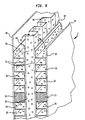
- Figure 6 is a fragmentary perspective view of Figure 4 with portions of the heat exchanger broken away to illustrate a liquid distribution system in accordance with the present invention.
- In Figures 3 and 6, the fragmentary views are taken with side bars removed in order to show the heat exchanger internals.
- With reference to Figures 1, 2 and 3 of the drawings, a heat exchanger 1 in accordance with the present invention is illustrated. Heat exchanger 1 has inlet
manifolds heat exchanger core 10. The first fluid is typically nitrogen vapour to be condensed and second fluid is typically liquid oxygen to be vaporised. The condensed nitrogen is discharged from heat exchanger 1 through anoutlet manifold 16. - Core 10 is fabricated to be open at the bottom so that the second fluid (liquid oxygen) not vaporised within heat exchanger 1 simply falls from
core 10. Thus, heat exchanger 1 is typically used in connection with a sump, either a separate tank or a sump of a distillation column, for example, the liquid oxygen sump of a lower pressure column of a double column air separation unit. -
Core 10 is formed of a first array of spaced apartparallel plates 18 to define first and secondheat exchange passages heat exchange passages 20 and the second fluid flows throughheat exchange passages 22 so that heat is indirectly transferred between the first and second fluids. - In a conventional manner, dividing
bars 23 seal firstheat exchange passages 20 at the top ofcore 10. Although not illustrated, similar dividing bars seal firstheat exchange passages 20 at the bottom ofcore 10. The first fluid enters firstheat exchange passages 20 from theinlet manifold 12 in a horizontal direction and is conducted by corrugated fin-type material 24 with horizontal corrugations. Corrugated fin-type material with inclined corrugations (not illustrated, but in a known manner) causes a transition in the flow from the horizontal to the vertical. Thereafter, the first fluid flows in a vertical direction, down firstheat exchange passages 20. Corrugated fin-type material 25 having vertical corrugations is provided in both first and secondheat exchange passages - The second fluid is fed in liquid state from the
inlet manifold 14 into a distributor means including a second array of parallel, spaced apartplates heat exchange passage 22, and each second channel is located vertically above a respective firstheat exchange passage 20. Eachplate heat exchange plate 18 and has a bottom edge located vertically above and spaced from the top edge of thecorresponding plate 18 so as to form an elongate gap therebetween. The liquid flows from the inlet manifold first to the first channels. A head or pool of liquid is thus established in each first channel. Liquid flows from the first channels over weirs defined by theparallel plates weirs 26 are all of the same height. Thus, uniform distribution of the liquid is facilitated. In order further to facilitate uniform distribution of the liquid, the first and second channels are each provided with asheet - Each
sheet 25 of corrugated fin type material in the secondheat exchange passages 22 extends above the top edges of theplates 18.Corrugations 36 of one such sheet are shown in Figure 3. Liquid flows out of each second channel by virtue of the liquid head through the elongate gaps defined between the bottom edges of theplates plates 18. The liquid is thus fed to both sides of each sheet of corrugatedfin type material 25 extending above the top of theplates 18. Uniform distribution of the liquid to the secondheat exchange passages 22 is therefore facilitated. - Each first channel is separated at its bottom from a respective second
heat exchange passage 22 located vertically thereabove by means of a dividingbar 34 abutting the top edge of the extended section of arespective sheet 25 of corrugated fin material. - In order to prevent liquid, entering through
inlet manifold 14, from flowing directly into the first channels frominlet manifold 14,side bars 40 are provided (which have been removed in the fragmentary illustration of Figure 3).Side bars 40 have a gap at the location of horizontally oriented, corrugated fin-type material 24 to allow first fluid to be fed frominlet manifold 12. In this regard,inlet manifold 12 is situated at such gap and, thus, opposite to horizontally oriented, corrugated fin-type material 25.Side bars 41 seal the secondheat exchange passages 22. In order to allow liquid to flow into the first channels , theside bars 41 do not extend past dividingbars 34. First and secondheat exchange passages side bars side bars 42. As can be appreciated, theside bars 42 that are associated with firstheat exchange passages 20 are set aboveoutlet manifold 16 so that the second fluid can be discharged frommanifold 16.Side bars 42 that are associated with secondheat exchange passages 22 run the full height ofheat exchanger core 10 because secondheat exchange passages 22 are open at the bottom thereof. - The
plates heat exchange passages 22 are provided with rectangular, slot-like cut outsections 44 of a desired depth so as to give a chosen height of liquid head in the second channels. - With reference to Figures 4, 5 and 6, an alternative embodiment of a
heat exchanger 2 in accordance with the present invention is illustrated. In these illustrations, reference numerals that were used in describing heat exchanger 1 are repeated for components that are the same or repeated inheat exchanger 2. - In
heat exchanger 2, as with the embodiment shown in Figures 1-3,corrugated fin material 25 is fabricated to extend beyond secondheat exchange passages 22 so thatcorrugations 36 can all be wetted with the liquid. However, instead of there beingseparate plates plates 18 all extend above saidheat exchange passages weirs 26. The first channels are thus positioned vertically above the firstheat exchange passages 20 and are separated therefrom by the dividing bars 23. Each second channel is located vertically above a corresponding second heat exchange passage and there are no dividing bars therebetween. There is thus free flow of liquid from each second channel into a corresponding first channel. Liquid flows over theweirs 26 in the direction of arrowheads A and B intocorrugations 36 ofcorrugated fin material 25. The top of eachplate 18 is provided with a rectangular, slot-like cut-outsection 44 of chosen depth adjacentcorrugated fin material 25 of secondheat exchange passages 22. - Referring still to Figures 4 to 6 of the drawings, side bars 40 run the full height of
heat exchanger core 10. Side bars 41 extend only up tofirst inlet manifold 12 to allow the first fluid to enter firstheat exchange passages 20 through horizontally oriented,corrugated fin material 24. As such, dividing bars 23 extend so that, at their ends, they separate first and second inlet manifolds 12 and 14.Heat exchanger core 10 is sealed opposite to side bars 40 and 41 by side bars 42. Side bars 42 that are associated with firstheat exchange passages 20 are set aboveoutlet manifold 16 so that the second fluid can be discharged fromoutlet manifold 16. Side bars 42 that are associated with secondheat exchange passages 22 run the full height ofheat exchanger core 10 as the secondheat exchange passages 22 are open at the bottom thereof for the discharge of liquid. - The
heat exchanger core 10 in both Figures 1 and 2 can be capped to prevent the escape of vaporised liquid and to more securelyweld inlet manifold 14 toheat exchanger core 10. Such a construction is well known in the art.
Claims (7)
- A heat exchanger for indirectly exchanging heat between first and second fluids, said heat exchanger comprising:a first array of spaced apart, vertical plates defining a plurality of alternating first and second heat exchange passages for said first and second fluids to undergo indirect heat exchange;corrugated sheet material within said first and second heat exchange passages to increase heat transfer area within said first and second heat exchange passages;first inlet and outlet means for introducing said first fluid into said first heat exchange passages and for discharging said first fluid from said first heat exchange passages, respectively;means for distributing liquid into said second heat exchange passages, said liquid distribution means having weirs over which, in use, said liquid flows and falls into said second heat exchange passages, said weirs positioned to feed both sides of each of said second heat exchange passages, and said corrugated sheet material of said second heat exchange passages extending above said second heat exchange passages so as, in use, to receive said liquid in each of the corrugations; and second inlet means for introducing said second fluid, as said liquid, to said weirs.
- A heat exchanger as claimed in claim 1, wherein said distributor means includes a second array of spaced apart vertical plates which define said weirs, each plate in the second array being aligned with a corresponding plate in the first array, and having a bottom edge spaced above the top edge of the corresponding plate so as to define a gap therebetween through which liquid is able to flow and be received by the liquid receiving portions of an associated sheet of said corrugated material.
- A heat exchanger as claimed in claim 1, wherein said plates continue above said heat exchange passages and form said weirs.
- A heat exchanger as claimed in claim 2, wherein said second array of spaced, vertical plates provides alternate first and second channels, each first channel being located above a corresponding second heat exchange passage, and said second inlet means communicates with said first channels, whereby, in use, liquid flows from the first channels over the weirs into the second channels.
- A heat exchanger as claimed in claim 3, wherein said plates form alternate first and second channels, each second channel being located above and contiguous to a corresponding second heat exchange passage, and said second inlet means communicates with said first channels, whereby, in use, liquid flows from the first channels over the weirs into the second channels.
- A heat exchanger as claimed in claim 4 or claim 5, wherein the second channels are arranged so as, in use, to contain a head of liquid under which liquid flows onto the liquid receiving portions of said corrugated sheet material.
- A heat exchanger as claimed in any one of claims 4 to 6, in which each said first and second channel contains a corrugated sheet member disposed such that its corrugations run horizontally.
Applications Claiming Priority (2)
| Application Number | Priority Date | Filing Date | Title |
|---|---|---|---|
| US625483 | 1996-03-29 | ||
| US08/625,483 US5755279A (en) | 1996-03-29 | 1996-03-29 | Heat exchanger |
Publications (2)
| Publication Number | Publication Date |
|---|---|
| EP0798528A2 true EP0798528A2 (en) | 1997-10-01 |
| EP0798528A3 EP0798528A3 (en) | 1999-02-24 |
Family
ID=24506303
Family Applications (1)
| Application Number | Title | Priority Date | Filing Date |
|---|---|---|---|
| EP97302197A Withdrawn EP0798528A3 (en) | 1996-03-29 | 1997-03-27 | Heat Exchanger |
Country Status (12)
| Country | Link |
|---|---|
| US (1) | US5755279A (en) |
| EP (1) | EP0798528A3 (en) |
| JP (1) | JPH1030895A (en) |
| KR (1) | KR970066503A (en) |
| CN (1) | CN1165285A (en) |
| AU (1) | AU1255997A (en) |
| CA (1) | CA2198323A1 (en) |
| ID (1) | ID16350A (en) |
| PL (1) | PL319212A1 (en) |
| SG (1) | SG48519A1 (en) |
| TW (1) | TW353139B (en) |
| ZA (1) | ZA972510B (en) |
Cited By (2)
| Publication number | Priority date | Publication date | Assignee | Title |
|---|---|---|---|---|
| WO1999042780A1 (en) * | 1998-02-17 | 1999-08-26 | Chart Marston Limited | Heat exchangers |
| EP1236505A1 (en) * | 2001-02-27 | 2002-09-04 | Methanol Casale S.A. | Method for carrying out chemical reactions in pseudo-isothermal conditions |
Families Citing this family (10)
| Publication number | Priority date | Publication date | Assignee | Title |
|---|---|---|---|---|
| FR2798598B1 (en) * | 1999-09-21 | 2002-05-24 | Air Liquide | BATH VAPORIZER-CONDENSER AND CORRESPONDING AIR DISTILLATION APPARATUS |
| US6606882B1 (en) * | 2002-10-23 | 2003-08-19 | Carrier Corporation | Falling film evaporator with a two-phase flow distributor |
| US7163051B2 (en) * | 2003-08-28 | 2007-01-16 | Praxair Technology, Inc. | Heat exchanger distributor for multicomponent heat exchange fluid |
| CN100365372C (en) * | 2005-11-16 | 2008-01-30 | 杭州钦宝制冷设备有限公司 | Three-way guidance tape typed heat exchanger |
| US8043417B2 (en) * | 2008-06-30 | 2011-10-25 | Uop Llc | Column installed condenser |
| CZ303570B6 (en) * | 2011-10-06 | 2012-12-12 | Ehrlich@Jindrich | Contact-type heat exchange apparatus |
| US9683784B2 (en) | 2012-01-27 | 2017-06-20 | Carrier Corporation | Evaporator and liquid distributor |
| JP5938243B2 (en) * | 2012-03-16 | 2016-06-22 | 住友精密工業株式会社 | Tower condenser |
| CN103994677B (en) * | 2014-04-30 | 2015-10-21 | 叶立英 | Indirect evaporative cooling core |
| JP6783836B2 (en) * | 2018-09-19 | 2020-11-11 | 株式会社前川製作所 | Plate polymer and heat exchanger |
Family Cites Families (7)
| Publication number | Priority date | Publication date | Assignee | Title |
|---|---|---|---|---|
| US3992168A (en) * | 1968-05-20 | 1976-11-16 | Kobe Steel Ltd. | Heat exchanger with rectification effect |
| GB1299481A (en) * | 1970-05-06 | 1972-12-13 | Apv Co Ltd | Improvements in or relating to evaporators |
| JPS5993181A (en) * | 1982-11-19 | 1984-05-29 | Hitachi Ltd | Liquid film vaporization type heat exchanger |
| US4614229A (en) * | 1983-06-20 | 1986-09-30 | Exxon Research & Engineering Co. | Method and apparatus for efficient recovery of heat from hot gases that tend to foul heat exchanger tubes |
| FR2547898B1 (en) * | 1983-06-24 | 1985-11-29 | Air Liquide | METHOD AND DEVICE FOR VAPORIZING A LIQUID BY HEAT EXCHANGE WITH A SECOND FLUID, AND THEIR APPLICATION TO AN AIR DISTILLATION INSTALLATION |
| FR2685071B1 (en) * | 1991-12-11 | 1996-12-13 | Air Liquide | INDIRECT PLATE TYPE HEAT EXCHANGER. |
| US5438836A (en) * | 1994-08-05 | 1995-08-08 | Praxair Technology, Inc. | Downflow plate and fin heat exchanger for cryogenic rectification |
-
1996
- 1996-03-29 US US08/625,483 patent/US5755279A/en not_active Expired - Fee Related
-
1997
- 1997-02-04 TW TW086101327A patent/TW353139B/en active
- 1997-02-05 SG SG1997000252A patent/SG48519A1/en unknown
- 1997-02-06 AU AU12559/97A patent/AU1255997A/en not_active Abandoned
- 1997-02-12 CN CN97102442A patent/CN1165285A/en active Pending
- 1997-02-19 ID IDP970475A patent/ID16350A/en unknown
- 1997-02-24 CA CA002198323A patent/CA2198323A1/en not_active Abandoned
- 1997-03-24 ZA ZA9702510A patent/ZA972510B/en unknown
- 1997-03-27 EP EP97302197A patent/EP0798528A3/en not_active Withdrawn
- 1997-03-28 JP JP9077138A patent/JPH1030895A/en active Pending
- 1997-03-28 KR KR1019970011287A patent/KR970066503A/en not_active Ceased
- 1997-03-28 PL PL97319212A patent/PL319212A1/en unknown
Cited By (3)
| Publication number | Priority date | Publication date | Assignee | Title |
|---|---|---|---|---|
| WO1999042780A1 (en) * | 1998-02-17 | 1999-08-26 | Chart Marston Limited | Heat exchangers |
| EP1236505A1 (en) * | 2001-02-27 | 2002-09-04 | Methanol Casale S.A. | Method for carrying out chemical reactions in pseudo-isothermal conditions |
| WO2002068110A1 (en) * | 2001-02-27 | 2002-09-06 | Methanol Casale S.A. | Method for carrying out chemical reactions in pseudo-isothermal conditions |
Also Published As
| Publication number | Publication date |
|---|---|
| CN1165285A (en) | 1997-11-19 |
| KR970066503A (en) | 1997-10-13 |
| ID16350A (en) | 1997-09-25 |
| AU1255997A (en) | 1997-10-02 |
| TW353139B (en) | 1999-02-21 |
| CA2198323A1 (en) | 1997-09-30 |
| SG48519A1 (en) | 1998-04-17 |
| JPH1030895A (en) | 1998-02-03 |
| US5755279A (en) | 1998-05-26 |
| EP0798528A3 (en) | 1999-02-24 |
| PL319212A1 (en) | 1997-10-13 |
| ZA972510B (en) | 1997-10-20 |
Similar Documents
| Publication | Publication Date | Title |
|---|---|---|
| CA2195181C (en) | Heat exchanger | |
| US4511436A (en) | Apparatus for the desalination of sea water | |
| US3983191A (en) | Brazed plate-type heat exchanger for nonadiabatic rectification | |
| US3568462A (en) | Fractionating device | |
| US7111673B2 (en) | System for stripping and rectifying a fluid mixture | |
| JP3076061B2 (en) | Simultaneous transfer of material and heat | |
| EP0798528A2 (en) | Heat Exchanger | |
| US7445040B2 (en) | Heat exchange fin and the production method thereof | |
| JPH0531042B2 (en) | ||
| GB2089226A (en) | Plate evaporator | |
| US3792842A (en) | Rectifying tower | |
| CA2200947A1 (en) | Heat exchanger | |
| US3568461A (en) | Fractionation apparatus | |
| US4574007A (en) | Fractionating apparatus | |
| US7678237B2 (en) | Heat integrated distillation column | |
| RU2077010C1 (en) | Heat exchanger with jet escape of liquid and plant for separation of air by distillation | |
| EP0759317B1 (en) | Apparatus for combined heat and mass transfer | |
| EP1067347B1 (en) | Downflow liquid film type condensation evaporator | |
| USRE33026E (en) | Process and device for vaporizing a liquid by heat exchange with a second fluid and their application in an air distillation installation | |
| US5775129A (en) | Heat exchanger | |
| US20220126263A1 (en) | Matrix integrating at least one heat exchange function and one distillation function | |
| EP0780646A2 (en) | Heat exchanger and double distillation column | |
| JP4210088B2 (en) | Gas-liquid distribution structure | |
| CA2053971C (en) | Tower packing with small and large louvers | |
| GB2316478A (en) | Liquefaction heat exchanger |
Legal Events
| Date | Code | Title | Description |
|---|---|---|---|
| PUAI | Public reference made under article 153(3) epc to a published international application that has entered the european phase |
Free format text: ORIGINAL CODE: 0009012 |
|
| AK | Designated contracting states |
Kind code of ref document: A2 Designated state(s): BE DE FR GB IE IT NL SE |
|
| PUAL | Search report despatched |
Free format text: ORIGINAL CODE: 0009013 |
|
| AK | Designated contracting states |
Kind code of ref document: A3 Designated state(s): BE DE FR GB IE IT NL SE |
|
| 17P | Request for examination filed |
Effective date: 19990818 |
|
| 17Q | First examination report despatched |
Effective date: 20010402 |
|
| GRAG | Despatch of communication of intention to grant |
Free format text: ORIGINAL CODE: EPIDOS AGRA |
|
| GRAG | Despatch of communication of intention to grant |
Free format text: ORIGINAL CODE: EPIDOS AGRA |
|
| GRAH | Despatch of communication of intention to grant a patent |
Free format text: ORIGINAL CODE: EPIDOS IGRA |
|
| STAA | Information on the status of an ep patent application or granted ep patent |
Free format text: STATUS: THE APPLICATION IS DEEMED TO BE WITHDRAWN |
|
| 18D | Application deemed to be withdrawn |
Effective date: 20030218 |