EP0798457B1 - Dispositif de pompage de carburant pour reservoir multipoches - Google Patents
Dispositif de pompage de carburant pour reservoir multipoches Download PDFInfo
- Publication number
- EP0798457B1 EP0798457B1 EP19970400706 EP97400706A EP0798457B1 EP 0798457 B1 EP0798457 B1 EP 0798457B1 EP 19970400706 EP19970400706 EP 19970400706 EP 97400706 A EP97400706 A EP 97400706A EP 0798457 B1 EP0798457 B1 EP 0798457B1
- Authority
- EP
- European Patent Office
- Prior art keywords
- fuel
- pump
- compartment
- pumping device
- Prior art date
- Legal status (The legal status is an assumption and is not a legal conclusion. Google has not performed a legal analysis and makes no representation as to the accuracy of the status listed.)
- Expired - Lifetime
Links
Images


Classifications
-
- F—MECHANICAL ENGINEERING; LIGHTING; HEATING; WEAPONS; BLASTING
- F02—COMBUSTION ENGINES; HOT-GAS OR COMBUSTION-PRODUCT ENGINE PLANTS
- F02D—CONTROLLING COMBUSTION ENGINES
- F02D33/00—Controlling delivery of fuel or combustion-air, not otherwise provided for
- F02D33/003—Controlling the feeding of liquid fuel from storage containers to carburettors or fuel-injection apparatus ; Failure or leakage prevention; Diagnosis or detection of failure; Arrangement of sensors in the fuel system; Electric wiring; Electrostatic discharge
-
- B—PERFORMING OPERATIONS; TRANSPORTING
- B60—VEHICLES IN GENERAL
- B60K—ARRANGEMENT OR MOUNTING OF PROPULSION UNITS OR OF TRANSMISSIONS IN VEHICLES; ARRANGEMENT OR MOUNTING OF PLURAL DIVERSE PRIME-MOVERS IN VEHICLES; AUXILIARY DRIVES FOR VEHICLES; INSTRUMENTATION OR DASHBOARDS FOR VEHICLES; ARRANGEMENTS IN CONNECTION WITH COOLING, AIR INTAKE, GAS EXHAUST OR FUEL SUPPLY OF PROPULSION UNITS IN VEHICLES
- B60K15/00—Arrangement in connection with fuel supply of combustion engines or other fuel consuming energy converters, e.g. fuel cells; Mounting or construction of fuel tanks
- B60K15/03—Fuel tanks
- B60K15/077—Fuel tanks with means modifying or controlling distribution or motion of fuel, e.g. to prevent noise, surge, splash or fuel starvation
-
- F—MECHANICAL ENGINEERING; LIGHTING; HEATING; WEAPONS; BLASTING
- F02—COMBUSTION ENGINES; HOT-GAS OR COMBUSTION-PRODUCT ENGINE PLANTS
- F02M—SUPPLYING COMBUSTION ENGINES IN GENERAL WITH COMBUSTIBLE MIXTURES OR CONSTITUENTS THEREOF
- F02M37/00—Apparatus or systems for feeding liquid fuel from storage containers to carburettors or fuel-injection apparatus; Arrangements for purifying liquid fuel specially adapted for, or arranged on, internal-combustion engines
- F02M37/0076—Details of the fuel feeding system related to the fuel tank
- F02M37/0088—Multiple separate fuel tanks or tanks being at least partially partitioned
- F02M37/0094—Saddle tanks; Tanks having partition walls
-
- F—MECHANICAL ENGINEERING; LIGHTING; HEATING; WEAPONS; BLASTING
- F02—COMBUSTION ENGINES; HOT-GAS OR COMBUSTION-PRODUCT ENGINE PLANTS
- F02M—SUPPLYING COMBUSTION ENGINES IN GENERAL WITH COMBUSTIBLE MIXTURES OR CONSTITUENTS THEREOF
- F02M37/00—Apparatus or systems for feeding liquid fuel from storage containers to carburettors or fuel-injection apparatus; Arrangements for purifying liquid fuel specially adapted for, or arranged on, internal-combustion engines
- F02M37/04—Feeding by means of driven pumps
- F02M37/08—Feeding by means of driven pumps electrically driven
- F02M37/10—Feeding by means of driven pumps electrically driven submerged in fuel, e.g. in reservoir
- F02M37/106—Feeding by means of driven pumps electrically driven submerged in fuel, e.g. in reservoir the pump being installed in a sub-tank
-
- B—PERFORMING OPERATIONS; TRANSPORTING
- B60—VEHICLES IN GENERAL
- B60K—ARRANGEMENT OR MOUNTING OF PROPULSION UNITS OR OF TRANSMISSIONS IN VEHICLES; ARRANGEMENT OR MOUNTING OF PLURAL DIVERSE PRIME-MOVERS IN VEHICLES; AUXILIARY DRIVES FOR VEHICLES; INSTRUMENTATION OR DASHBOARDS FOR VEHICLES; ARRANGEMENTS IN CONNECTION WITH COOLING, AIR INTAKE, GAS EXHAUST OR FUEL SUPPLY OF PROPULSION UNITS IN VEHICLES
- B60K15/00—Arrangement in connection with fuel supply of combustion engines or other fuel consuming energy converters, e.g. fuel cells; Mounting or construction of fuel tanks
- B60K15/03—Fuel tanks
- B60K2015/03105—Fuel tanks with supplementary interior tanks inside the fuel tank
-
- B—PERFORMING OPERATIONS; TRANSPORTING
- B60—VEHICLES IN GENERAL
- B60K—ARRANGEMENT OR MOUNTING OF PROPULSION UNITS OR OF TRANSMISSIONS IN VEHICLES; ARRANGEMENT OR MOUNTING OF PLURAL DIVERSE PRIME-MOVERS IN VEHICLES; AUXILIARY DRIVES FOR VEHICLES; INSTRUMENTATION OR DASHBOARDS FOR VEHICLES; ARRANGEMENTS IN CONNECTION WITH COOLING, AIR INTAKE, GAS EXHAUST OR FUEL SUPPLY OF PROPULSION UNITS IN VEHICLES
- B60K15/00—Arrangement in connection with fuel supply of combustion engines or other fuel consuming energy converters, e.g. fuel cells; Mounting or construction of fuel tanks
- B60K15/03—Fuel tanks
- B60K2015/03118—Multiple tanks, i.e. two or more separate tanks
-
- B—PERFORMING OPERATIONS; TRANSPORTING
- B60—VEHICLES IN GENERAL
- B60K—ARRANGEMENT OR MOUNTING OF PROPULSION UNITS OR OF TRANSMISSIONS IN VEHICLES; ARRANGEMENT OR MOUNTING OF PLURAL DIVERSE PRIME-MOVERS IN VEHICLES; AUXILIARY DRIVES FOR VEHICLES; INSTRUMENTATION OR DASHBOARDS FOR VEHICLES; ARRANGEMENTS IN CONNECTION WITH COOLING, AIR INTAKE, GAS EXHAUST OR FUEL SUPPLY OF PROPULSION UNITS IN VEHICLES
- B60K15/00—Arrangement in connection with fuel supply of combustion engines or other fuel consuming energy converters, e.g. fuel cells; Mounting or construction of fuel tanks
- B60K15/03—Fuel tanks
- B60K2015/03118—Multiple tanks, i.e. two or more separate tanks
- B60K2015/03138—Pumping means between the compartments
-
- B—PERFORMING OPERATIONS; TRANSPORTING
- B60—VEHICLES IN GENERAL
- B60K—ARRANGEMENT OR MOUNTING OF PROPULSION UNITS OR OF TRANSMISSIONS IN VEHICLES; ARRANGEMENT OR MOUNTING OF PLURAL DIVERSE PRIME-MOVERS IN VEHICLES; AUXILIARY DRIVES FOR VEHICLES; INSTRUMENTATION OR DASHBOARDS FOR VEHICLES; ARRANGEMENTS IN CONNECTION WITH COOLING, AIR INTAKE, GAS EXHAUST OR FUEL SUPPLY OF PROPULSION UNITS IN VEHICLES
- B60K15/00—Arrangement in connection with fuel supply of combustion engines or other fuel consuming energy converters, e.g. fuel cells; Mounting or construction of fuel tanks
- B60K15/03—Fuel tanks
- B60K2015/03118—Multiple tanks, i.e. two or more separate tanks
- B60K2015/03144—Fluid connections between the tanks
-
- B—PERFORMING OPERATIONS; TRANSPORTING
- B60—VEHICLES IN GENERAL
- B60K—ARRANGEMENT OR MOUNTING OF PROPULSION UNITS OR OF TRANSMISSIONS IN VEHICLES; ARRANGEMENT OR MOUNTING OF PLURAL DIVERSE PRIME-MOVERS IN VEHICLES; AUXILIARY DRIVES FOR VEHICLES; INSTRUMENTATION OR DASHBOARDS FOR VEHICLES; ARRANGEMENTS IN CONNECTION WITH COOLING, AIR INTAKE, GAS EXHAUST OR FUEL SUPPLY OF PROPULSION UNITS IN VEHICLES
- B60K15/00—Arrangement in connection with fuel supply of combustion engines or other fuel consuming energy converters, e.g. fuel cells; Mounting or construction of fuel tanks
- B60K15/03—Fuel tanks
- B60K2015/03118—Multiple tanks, i.e. two or more separate tanks
- B60K2015/03151—Mechanical connection between the tanks
-
- B—PERFORMING OPERATIONS; TRANSPORTING
- B60—VEHICLES IN GENERAL
- B60K—ARRANGEMENT OR MOUNTING OF PROPULSION UNITS OR OF TRANSMISSIONS IN VEHICLES; ARRANGEMENT OR MOUNTING OF PLURAL DIVERSE PRIME-MOVERS IN VEHICLES; AUXILIARY DRIVES FOR VEHICLES; INSTRUMENTATION OR DASHBOARDS FOR VEHICLES; ARRANGEMENTS IN CONNECTION WITH COOLING, AIR INTAKE, GAS EXHAUST OR FUEL SUPPLY OF PROPULSION UNITS IN VEHICLES
- B60K15/00—Arrangement in connection with fuel supply of combustion engines or other fuel consuming energy converters, e.g. fuel cells; Mounting or construction of fuel tanks
- B60K15/03—Fuel tanks
- B60K2015/0321—Fuel tanks characterised by special sensors, the mounting thereof
- B60K2015/03217—Fuel level sensors
-
- B—PERFORMING OPERATIONS; TRANSPORTING
- B60—VEHICLES IN GENERAL
- B60K—ARRANGEMENT OR MOUNTING OF PROPULSION UNITS OR OF TRANSMISSIONS IN VEHICLES; ARRANGEMENT OR MOUNTING OF PLURAL DIVERSE PRIME-MOVERS IN VEHICLES; AUXILIARY DRIVES FOR VEHICLES; INSTRUMENTATION OR DASHBOARDS FOR VEHICLES; ARRANGEMENTS IN CONNECTION WITH COOLING, AIR INTAKE, GAS EXHAUST OR FUEL SUPPLY OF PROPULSION UNITS IN VEHICLES
- B60K15/00—Arrangement in connection with fuel supply of combustion engines or other fuel consuming energy converters, e.g. fuel cells; Mounting or construction of fuel tanks
- B60K15/03—Fuel tanks
- B60K2015/03236—Fuel tanks characterised by special filters, the mounting thereof
Definitions
- the present invention relates to the field of devices for fuel pumping for multi-pocket tanks. It aims more particularly a device for controlling an electric pump fuel placed between tank pockets, in particular for vehicles automobile.
- Some motor vehicles have fuel tanks. multi-pocket fuel. The pockets of these tanks are distributed in the structure of the vehicle, for example on either side of an axle, and communicate with each other.
- the pockets of such tanks can be removed or arranged on different levels or separated by a partitioning. Subsequently, the fuel does not flow naturally to the main fuel pumping point, usually located in a main pocket, from which the fuel is directed to the engine.
- a disadvantage of such a device is the overpressure which appears in the Venturi tube and in the return line. These devices are not suitable for diesel engines in which the pump does not tolerate overpressure on the return line at tank.
- Document DE-A-4027948 describes with reference to its FIG. 1, a fuel pumping device comprising in a tank 1 a reserve bowl 8, a pump 9 actuated by a motor 10 adapted for pump fuel into bowl 8 and direct it to an injector rail 2, and a pump 11 actuated by a motor 11.1 adapted to take from fuel in tank 1 and transfer it to the reserve bowl 8.
- the pump 11 is controlled by a control module 6 itself controlled by level sensors 16U, 160 placed on the reserve bowl 8.
- document DE-A-4027948 does not concern a multi-pocket tank like the invention, but a single-pocket tank equipped with a reserve bowl.
- the pump 11 is controlled by sensors 16 placed on the bowl of reserve, i.e. on the destination volume. Such a provision does not not satisfactory.
- An object of the present invention is to remedy the aforementioned drawbacks.
- This object is achieved according to the invention by carrying out a fuel pumping device for a multi-pocket tank, in particular motor vehicle, comprising a main pump collecting the fuel in a main pocket to direct it to a place of use, at least one electric secondary pump capable of transferring fuel from a secondary pocket to the main pocket, and a control circuit of the electric secondary pump in which the circuit piloting includes a detection of the fuel level in the pocket secondary, so that the circuit interrupts the operation of the secondary pump when a minimum level is detected in the pocket secondary.
- An advantage of such a device is that it avoids operation dry of the electric pump which could cause its destruction.
- the pump compresses air and the actuators heat up and may cause thermal destruction of the pump.
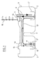
- the device according to the invention comprises a multi-pocket reservoir 3 comprising a main pocket 1 and a separate secondary pocket 2 by a partition 4, at their base, but communicating with each other at their part superior.
- the invention can be implemented on tanks comprising a greater number of pockets, or even insulated pockets, not separated by a partition.
- fuel is pumped into the pocket main 1 by a flow line 5 connected to a pump main (not shown).
- Pumping is preferably carried out in a reserve basin or bowl 1 'disposed at the bottom of the pocket 1.
- Such a basin 1 ' stabilizes the fuel during vehicle movements.
- a fuel return line 6 ends in this bowl 1. The fuel not consumed by the engine is thus returned to the bowl 1 '.
- the secondary pocket 2 similarly may include a 2 'basin or bowl.
- a transfer line 10 connects this pocket 2 to the pocket main 1.
- Such a pipe 10 preferably takes the fuel near the bottom of the basin or bowl 2 'to discharge it into the basin or bowl 1'.
- a pump electrical secondary It is arranged on the pipe 10 connecting the bag 2 to the pocket 1.
- Such an electric pump 11 is controlled by a circuit of control 13.
- Wiring 14 makes it possible to connect the electric pump 11 to the control circuit 13, preferably arranged outside the tank 1.
- control circuit includes a detection of the fuel level present in the secondary pocket 2 of preferably in the 2 'bowl. On this detection, the control circuit 13 can interrupt the operation of the electric pump 11 when the fuel level in the secondary pocket 2 or in the bowl 2 'is in below a threshold. Thus, it is advantageously avoided that the pump 11 is not damaged by dry running.
- detection is performed by a detector 12 arranged in the secondary pocket 2, preferably at inside the pool 2 '.
- the detector 12 is connected to the control circuit 13 by wiring 15.
- detectors can either provide a measure proportional to the level of fuel, or provide an all or nothing indication, according to two states: below an alert level or above this alert level.
- FIG. 2 illustrates thus a control circuit AR1 adapted to a contact detector K1.
- the contact K1 provides an indication of state I1.
- contact K1 is connected between a ground potential S- and an input I1 of the AR1 control circuit.
- I1 0.
- An example of such a detector is an alert tubular fuel tank contact. In such a device, a float, once it reaches the bottom of a sliding tube, closes a electrical contact indicating that the alert level is reached.
- the control circuit AR 1 is intended to control the operation of the electric pump 11.
- An output of circuit AR1 provides for example a control signal D1 triggering the operation of the pump 11.
- This signal D1 is preferably applied to the base of a power transistor T1, connected between a terminal P + and a + terminal of the pump 11.
- the other - terminal of the pump 11 is connected to the vehicle ground or power supply terminal P-.
- FIG. 2 we see for example that the collector of transistor T1, of PNP type, is connected to the + terminal of pump 11, the T1 transmitter being connected to the P + supply terminal.
- Other control devices may be used by those skilled in the art without departing from the scope of the present invention.
- the control circuit AR1 includes an anti-kickback filter.
- This filter can be for example a classic low pass filter or an inhibition delayed signal I1.
- Such a timed inhibition may consist of for example not to take into account the impulses Contact imp k1 illustrated in Figure 3 between times t1 and t2.
- the control signal D1 may, for example, be inactive for a period of time after the signal transition I1 (falling edge of time tl).
- the detector 12 is preferably a K1 electrical contact placed on a fuel gauge or alert contact tubular located in the secondary pocket 2.
- V0 and V1 are also shown.
- the V0 and V1 detectors are intended to be placed in the main pocket 1 and the secondary pocket 2 respectively.
- the V0 detector provides a first indication S0, of the level of fuel contained in the main pocket 1.
- the V1 detector provides a second indication S1 of fuel level in the pocket secondary 2.
- these detectors V0 and V1 can constitute elements of a fuel gauge providing an overall measure of the volume of fuel in the tank 3.
- the two signals S1 and S0 we add, after possible weighting, the two signals S1 and S0, to provide a signal measurement unit for a dashboard indicator device motor vehicle.
- an adder ADD receives the signal S1 on its input E1, the input E0 receiving the signal S0 from the proportional detector V0.
- the OUT output of the ADD adder is connected to an indicating device.
- a second embodiment has been envisaged to highlight works the invention with a proportional detector.
- a proportional detector proportional can only be used to control the pump operation or be used by both the circuit piloting and by the fuel gauge as described below.
- the invention provides for using the signal from a proportional detector V1 placed in the pocket secondary 2, for controlling the electric secondary pump 11.
- the detector V1 is therefore connected to an input S1 of the control circuit P1.
- the control circuit P1 receives a signal S1 proportional to the fuel level. However, this signal may be disturbed by agitation of the fuel in the tank. Level filtering is therefore provided in circuit P1. As shown in FIG. 5, one thus obtains, from a signal S1, a signal S1 'smoothed or filtered. This signal S1 'is then applied to a threshold detection circuit (threshold L indicated in dotted line in figure 5) to provide a signal command C1. This signal C1 can be applied to a power transistor T1, as previously described.
- An advantage of this embodiment is that the electric pump 11 is coherently controlled, the disturbances of signal S1 being eliminated to avoid inadvertent control of the pump 11.
- FIG. 5 thus shows that the electric pump 11 is maintained in operation until time t1, when the level means of the signal S1, therefore of the fuel, becomes lower than the threshold L.
- variable resistance R1 is advantageously arranged for this purpose outside the circuit P1 (see Figure 4).
- the fuel gauge is usually made up of multiple detectors proportional, each arranged in a pocket.
- the invention therefore plans to use one of the proportional detectors for both the gauge measurement and for the operating control of the secondary pump 11.
- the sinal S1 or the filtered signal S1 ' is added to the signal S0 measuring the fuel level in the main pocket 1.
- FIG. 4 thus shows an example of connection of the circuit P1, detectors V1, V0, and the adder ADD.
- output of circuit P1 providing the filtered signal S1 ' is connected to the input E1 of the ADD adder.
- the smoothed or filtered signal S1 ' is advantageously supplied to the fuel gauge.
- the detector V1 can be connected between a line S- and the input S1 of the driving circuit P1. This line S- can be coupled to ground or supply line P- by a decoupling capacitor K.
- Such a circuit makes it possible to use all types of resistive detectors, power being supplied by the control circuit P1 itself.
- the detector V1 can thus be a potentiometric sensor with float in contact with the resistive tracks of the potentiometer. According to one alternatively, the detector may be a thermistor. Other equivalents functional can be implemented without departing from the scope of the invention.
- connection socket 16 with four terminals S-, P-, P +, S +.
- the three S-, P-, P + terminals are connected to the corresponding S-, P-, P + lines, the point S + being an additional diagnostic terminal.
- S + is for example connected to a detector terminal V1 or K1 or to a terminal of the control circuit P1.
- This connection socket 16 thus allows a diagnostic of the operation of the control circuit 13 or a diagnostic of the operation of the gauge. It is also possible to detect a contact break or a short circuit of a detector.
- An accelerometer can thus be connected to the pump or to the control circuit.
Landscapes
- Engineering & Computer Science (AREA)
- Chemical & Material Sciences (AREA)
- Combustion & Propulsion (AREA)
- Mechanical Engineering (AREA)
- General Engineering & Computer Science (AREA)
- Life Sciences & Earth Sciences (AREA)
- Sustainable Development (AREA)
- Sustainable Energy (AREA)
- Transportation (AREA)
- Cooling, Air Intake And Gas Exhaust, And Fuel Tank Arrangements In Propulsion Units (AREA)
Description
- la figure 1 représente un dispositif de pompage selon l'invention ;
- la figure 2 représente un premier mode de réalisation de circuit de pilotage de dispositif de pompage selon l'invention ;
- la figure 3 représente un diagramme de signaux du circuit de la figure 2 ;
- la figure 4 représente un second mode de réalisation de circuit de pilotage de dispositif de pompage selon l'invention ;
- la figure 5 représente un diagramme de signaux du circuit de la figure 4.
Claims (10)
- Dispositif de pompage de carburant pour réservoir (3) multipoche, notamment de véhicule automobile, comprenant une pompe principale prélevant le carburant dans une poche principale pour le diriger vers un lieu d'utilisation, au moins une pompe secondaire (11) électrique, apte à transférer du carburant d'une poche secondaire (2) vers la poche principale (1) et un circuit de pilotage de la pompe secondaire électrique (11), caractérisé en ce que le circuit de pilotage (13) comporte une détection de niveau de carburant dans la poche secondaire (2), de sorte que le circuit interrompt le fonctionnement de la pompe secondaire électrique (11) lorsqu'un niveau minimal est détecté dans la poche secondaire.
- Dispositif de pompage selon la revendication 1, caractérisé par un filtrage de la détection de niveau, pour s'affranchir des oscillations du niveau de carburant.
- Dispositif de pompage selon la revendication 1 ou 2, caractérisé en ce que la détection de niveau est fournie par un détecteur (V1) de jauge de mesure du volume de carburant du réservoir (3).
- Dispositif de pompage selon l'une des revendications 1 à 3, caractérisé en ce que la détection de niveau est fournie par un détecteur proportionnel (V1) placé dans la poche secondaire 2.
- Dispositif de pompage selon l'une des revendications 1 à 4, caractérisé en ce que la détection de niveau est fournie par un détecteur résistif.
- Dispositif de pompage selon l'une des revendications 1 à 5, caractérisé en ce que la détection du niveau minimal est fournie par un détecteur à deux états.
- Dispositif de pompage selon l'une des revendications 1 à 6, caractérisé en ce que la détection de niveau est fournie par un contact électrique (K1).
- Dispositif de pompage selon l'une des revendications 1 à 7, caractérisé par le fait que le circuit de pilotage (13) est relié à une pièce de connexion (16) pour un autodiagnostic.
- Dispositif de pompage selon l'une des revendications 1 à 8, caractérisé par le fait que la détection de niveau est opérée dans un bol de réserve (2') présent dans la poche secondaire (2) et que la pompe secondaire (2') prélève le carburant dans ce bol de réserve (2') pour le transférer dans un second bol de réserve (1') présent dans la poche principale (1).
- Réservoir de carburant pour véhicule automobile, caractérisé par le fait qu'il est équipé d'un dispositif de pompage conforme à l'une des revendications 1 à 9.
Applications Claiming Priority (2)
| Application Number | Priority Date | Filing Date | Title |
|---|---|---|---|
| FR9603870 | 1996-03-28 | ||
| FR9603870A FR2746855B1 (fr) | 1996-03-28 | 1996-03-28 | Dispositif de pompage de carburant pour reservoir multipoches |
Publications (2)
| Publication Number | Publication Date |
|---|---|
| EP0798457A1 EP0798457A1 (fr) | 1997-10-01 |
| EP0798457B1 true EP0798457B1 (fr) | 2001-11-14 |
Family
ID=9490646
Family Applications (1)
| Application Number | Title | Priority Date | Filing Date |
|---|---|---|---|
| EP19970400706 Expired - Lifetime EP0798457B1 (fr) | 1996-03-28 | 1997-03-27 | Dispositif de pompage de carburant pour reservoir multipoches |
Country Status (3)
| Country | Link |
|---|---|
| EP (1) | EP0798457B1 (fr) |
| DE (1) | DE69708184T2 (fr) |
| FR (1) | FR2746855B1 (fr) |
Cited By (3)
| Publication number | Priority date | Publication date | Assignee | Title |
|---|---|---|---|---|
| DE10143819A1 (de) * | 2001-09-06 | 2003-04-10 | Siemens Ag | Kraftstoffmodul |
| DE102005008380A1 (de) * | 2005-02-23 | 2006-08-31 | Siemens Ag | Kraftstoffversorgungseinrichtung für ein Kraftfahrzeug |
| RU230310U1 (ru) * | 2024-05-15 | 2024-11-26 | Федеральное государственное автономное образовательное учреждение высшего образования "Московский политехнический университет" (Московский Политех) | Модуль подачи топлива |
Families Citing this family (7)
| Publication number | Priority date | Publication date | Assignee | Title |
|---|---|---|---|---|
| FR2771972B1 (fr) | 1997-12-10 | 2000-02-25 | Marwal Systems | Dispositif de reserve pour un reservoir de carburant de vehicule automobile |
| FR2777601B1 (fr) * | 1998-04-21 | 2000-12-22 | Marwal Systems | Dispositif de pompage de carburant comportant une pompe muie d'un orifice de degazage |
| DE10342081B4 (de) * | 2003-09-10 | 2006-08-10 | Siemens Ag | Kraftstoffbehälter für ein Kraftfahrzeug |
| GB0411659D0 (en) * | 2004-05-25 | 2004-06-30 | Bombardier Transp Gmbh | Fuel tank for a vehicle |
| DE102010051072B4 (de) * | 2010-11-12 | 2012-11-08 | Kautex Textron Gmbh & Co. Kg | Flüssigkeitsbehälter, insbesondere für eine wässrige Harnstofflösung |
| DE102013220615B4 (de) * | 2013-10-11 | 2020-09-03 | Vitesco Technologies GmbH | Fördereinheit |
| DE102021212907A1 (de) | 2021-11-17 | 2023-05-17 | Vitesco Technologies GmbH | Fördervorrichtung, Flüssigkeitstank mit einer derartigen Fördervorrichtung und Kraftfahrzeug mit einer derartigen Fördervorrichtung oder einem derartigen Flüssigkeitstank |
Family Cites Families (4)
| Publication number | Priority date | Publication date | Assignee | Title |
|---|---|---|---|---|
| JPH0681933B2 (ja) * | 1986-03-13 | 1994-10-19 | 日本電装株式会社 | 燃料供給ポンプ装置 |
| DE4027948B4 (de) * | 1990-09-04 | 2005-06-23 | Robert Bosch Gmbh | Kraftstoffversorgungssystem und Tankanlage für eine Brennkraftmaschine |
| JP2674337B2 (ja) * | 1991-03-20 | 1997-11-12 | トヨタ自動車株式会社 | 燃料供給装置 |
| US5111844A (en) * | 1991-10-28 | 1992-05-12 | General Motors Corporation | Automotive fuel system |
-
1996
- 1996-03-28 FR FR9603870A patent/FR2746855B1/fr not_active Expired - Fee Related
-
1997
- 1997-03-27 EP EP19970400706 patent/EP0798457B1/fr not_active Expired - Lifetime
- 1997-03-27 DE DE1997608184 patent/DE69708184T2/de not_active Expired - Fee Related
Cited By (6)
| Publication number | Priority date | Publication date | Assignee | Title |
|---|---|---|---|---|
| DE10143819A1 (de) * | 2001-09-06 | 2003-04-10 | Siemens Ag | Kraftstoffmodul |
| DE10143819B4 (de) * | 2001-09-06 | 2005-12-01 | Siemens Ag | Kraftstoffmodul |
| US7082931B2 (en) | 2001-09-06 | 2006-08-01 | Siemens Aktiengesellschaft | Fuel module |
| DE102005008380A1 (de) * | 2005-02-23 | 2006-08-31 | Siemens Ag | Kraftstoffversorgungseinrichtung für ein Kraftfahrzeug |
| US8485790B2 (en) | 2005-02-23 | 2013-07-16 | Continental Automotive Gmbh | Fuel supply unit for a motor vehicle |
| RU230310U1 (ru) * | 2024-05-15 | 2024-11-26 | Федеральное государственное автономное образовательное учреждение высшего образования "Московский политехнический университет" (Московский Политех) | Модуль подачи топлива |
Also Published As
| Publication number | Publication date |
|---|---|
| FR2746855B1 (fr) | 1998-06-19 |
| EP0798457A1 (fr) | 1997-10-01 |
| FR2746855A1 (fr) | 1997-10-03 |
| DE69708184T2 (de) | 2002-08-29 |
| DE69708184D1 (de) | 2001-12-20 |
Similar Documents
| Publication | Publication Date | Title |
|---|---|---|
| EP0434509B1 (fr) | Dispositif d'alimentation en ergol liquide pour véhicule spatial, adapté à la prédiction de sa fin de vie | |
| EP0261118B1 (fr) | Alimentation en energie electrique de circuits sur la roue pour un dispositif de surveillance des pneumatiques | |
| EP0798457A1 (fr) | Dispositif de pompage de carburant pour reservoir multipoches | |
| EP0337851B1 (fr) | Dispositif de filtration, notamment pour circuit de turbomachine | |
| FR2629876A1 (fr) | Dispositifs pour eliminer l'eau du gazole alimentant un moteur diesel | |
| FR2528583A1 (fr) | Dispositif de diagnostic de circuit de charge | |
| FR2909714A1 (fr) | Procede et dispositif de gestion d'unites d'entrainement. | |
| FR3065185B1 (fr) | Systeme de pressurisation de la cabine d'un engin travaillant dans un air charge de particules | |
| FR2907212A1 (fr) | Dispositif et procede de correction de la mesure de niveau d'un liquide contenu dans un recipient d'un vehicule en fonction de son inclinaison | |
| WO2008029056A2 (fr) | Agencement pour le remplissage en huile de lubrification, et la vidange d'un moteur sur un banc d'essais | |
| FR3012097A1 (fr) | Gestion des seuils de pression differentielle d’une pompe a vide reliee a un systeme de freinage de vehicule automobile | |
| FR2836709A1 (fr) | Mecanisme a engrenages a dispositif de controle pour la creation d'une atmosphere rarefiee | |
| EP0838361B1 (fr) | Dispositif de détection de la présence du bouchon d'un réservoir de carburant notamment de véhicule automobile | |
| EP1135589A1 (fr) | Ensemble de puisage de liquide, notamment pour additif de carburant | |
| FR2797300A1 (fr) | Systeme d'aide au declenchement de la regeneration d'un filtre a particules integre dans une ligne d'echappement d'un moteur de vehicule automobile | |
| FR2640556A1 (fr) | Procede et dispositif de commande du fonctionnement d'une pompe de transfert de carburant entre une chambre auxiliaire et une chambre principale d'un reservoir notamment d'un vehicule automobile | |
| EP0239448B1 (fr) | Dispositif de puisage et de jaugeage de carburant liquide pour réservoir de véhicule automobile | |
| FR2676686A1 (fr) | Dispositif de securite pour conducteurs de vehicules. | |
| EP0796421B1 (fr) | Dispositif de filtrage, notamment pour jauge de carburant sur vehicule automobile | |
| EP4295936B1 (fr) | Bloc de filtration pour piscine muni d'un système de mesure d'un niveau de colmatage et/ou de détection d'un état de colmatage d'un filtre | |
| EP0793014A1 (fr) | Circuit de détection du démarrage d'un moteur à combustion interne | |
| FR2766267A1 (fr) | Dispositif permettant de mesurer le niveau et la temperature d'un liquide tel que de l'huile de lubrification d'un moteur a combustion interne | |
| EP3728805B1 (fr) | Système de stockage de liquide pour véhicule | |
| FR2865005A1 (fr) | Systeme de purge automatique d'eau pour filtre a carburant. | |
| EP0519805A1 (fr) | Détection de la tension entre phases dans un régulateur d'alternateur |
Legal Events
| Date | Code | Title | Description |
|---|---|---|---|
| PUAI | Public reference made under article 153(3) epc to a published international application that has entered the european phase |
Free format text: ORIGINAL CODE: 0009012 |
|
| AK | Designated contracting states |
Kind code of ref document: A1 Designated state(s): DE ES GB IT |
|
| 17P | Request for examination filed |
Effective date: 19980309 |
|
| GRAG | Despatch of communication of intention to grant |
Free format text: ORIGINAL CODE: EPIDOS AGRA |
|
| 17Q | First examination report despatched |
Effective date: 20010312 |
|
| GRAG | Despatch of communication of intention to grant |
Free format text: ORIGINAL CODE: EPIDOS AGRA |
|
| GRAH | Despatch of communication of intention to grant a patent |
Free format text: ORIGINAL CODE: EPIDOS IGRA |
|
| GRAH | Despatch of communication of intention to grant a patent |
Free format text: ORIGINAL CODE: EPIDOS IGRA |
|
| GRAA | (expected) grant |
Free format text: ORIGINAL CODE: 0009210 |
|
| AK | Designated contracting states |
Kind code of ref document: B1 Designated state(s): DE ES GB IT |
|
| PG25 | Lapsed in a contracting state [announced via postgrant information from national office to epo] |
Ref country code: IT Free format text: LAPSE BECAUSE OF FAILURE TO SUBMIT A TRANSLATION OF THE DESCRIPTION OR TO PAY THE FEE WITHIN THE PRESCRIBED TIME-LIMIT;WARNING: LAPSES OF ITALIAN PATENTS WITH EFFECTIVE DATE BEFORE 2007 MAY HAVE OCCURRED AT ANY TIME BEFORE 2007. THE CORRECT EFFECTIVE DATE MAY BE DIFFERENT FROM THE ONE RECORDED. Effective date: 20011114 |
|
| RIN1 | Information on inventor provided before grant (corrected) |
Inventor name: TAUREL, JEAN-LUC Inventor name: DENNEULIN, DENIS |
|
| GBT | Gb: translation of ep patent filed (gb section 77(6)(a)/1977) |
Effective date: 20011114 |
|
| REF | Corresponds to: |
Ref document number: 69708184 Country of ref document: DE Date of ref document: 20011220 |
|
| REG | Reference to a national code |
Ref country code: GB Ref legal event code: IF02 |
|
| PG25 | Lapsed in a contracting state [announced via postgrant information from national office to epo] |
Ref country code: GB Free format text: LAPSE BECAUSE OF NON-PAYMENT OF DUE FEES Effective date: 20020327 |
|
| PG25 | Lapsed in a contracting state [announced via postgrant information from national office to epo] |
Ref country code: ES Free format text: LAPSE BECAUSE OF FAILURE TO SUBMIT A TRANSLATION OF THE DESCRIPTION OR TO PAY THE FEE WITHIN THE PRESCRIBED TIME-LIMIT Effective date: 20020530 |
|
| PLBE | No opposition filed within time limit |
Free format text: ORIGINAL CODE: 0009261 |
|
| STAA | Information on the status of an ep patent application or granted ep patent |
Free format text: STATUS: NO OPPOSITION FILED WITHIN TIME LIMIT |
|
| 26N | No opposition filed | ||
| GBPC | Gb: european patent ceased through non-payment of renewal fee |
Effective date: 20020327 |
|
| PGFP | Annual fee paid to national office [announced via postgrant information from national office to epo] |
Ref country code: DE Payment date: 20070430 Year of fee payment: 11 |
|
| PG25 | Lapsed in a contracting state [announced via postgrant information from national office to epo] |
Ref country code: DE Free format text: LAPSE BECAUSE OF NON-PAYMENT OF DUE FEES Effective date: 20081001 |