EP0798196B1 - Working vehicle - Google Patents
Working vehicle Download PDFInfo
- Publication number
- EP0798196B1 EP0798196B1 EP97109840A EP97109840A EP0798196B1 EP 0798196 B1 EP0798196 B1 EP 0798196B1 EP 97109840 A EP97109840 A EP 97109840A EP 97109840 A EP97109840 A EP 97109840A EP 0798196 B1 EP0798196 B1 EP 0798196B1
- Authority
- EP
- European Patent Office
- Prior art keywords
- clutch
- tension roller
- belt
- roller clutch
- engine
- Prior art date
- Legal status (The legal status is an assumption and is not a legal conclusion. Google has not performed a legal analysis and makes no representation as to the accuracy of the status listed.)
- Expired - Lifetime
Links
Images





Classifications
-
- F—MECHANICAL ENGINEERING; LIGHTING; HEATING; WEAPONS; BLASTING
- F16—ENGINEERING ELEMENTS AND UNITS; GENERAL MEASURES FOR PRODUCING AND MAINTAINING EFFECTIVE FUNCTIONING OF MACHINES OR INSTALLATIONS; THERMAL INSULATION IN GENERAL
- F16H—GEARING
- F16H7/00—Gearings for conveying rotary motion by endless flexible members
- F16H7/08—Means for varying tension of belts, ropes or chains
- F16H7/0827—Means for varying tension of belts, ropes or chains for disconnecting the drive
-
- B—PERFORMING OPERATIONS; TRANSPORTING
- B62—LAND VEHICLES FOR TRAVELLING OTHERWISE THAN ON RAILS
- B62D—MOTOR VEHICLES; TRAILERS
- B62D11/00—Steering non-deflectable wheels; Steering endless tracks or the like
- B62D11/02—Steering non-deflectable wheels; Steering endless tracks or the like by differentially driving ground-engaging elements on opposite vehicle sides
- B62D11/06—Steering non-deflectable wheels; Steering endless tracks or the like by differentially driving ground-engaging elements on opposite vehicle sides by means of a single main power source
- B62D11/10—Steering non-deflectable wheels; Steering endless tracks or the like by differentially driving ground-engaging elements on opposite vehicle sides by means of a single main power source using gearings with differential power outputs on opposite sides, e.g. twin-differential or epicyclic gears
- B62D11/14—Steering non-deflectable wheels; Steering endless tracks or the like by differentially driving ground-engaging elements on opposite vehicle sides by means of a single main power source using gearings with differential power outputs on opposite sides, e.g. twin-differential or epicyclic gears differential power outputs being effected by additional power supply to one side, e.g. power originating from secondary power source
- B62D11/18—Steering non-deflectable wheels; Steering endless tracks or the like by differentially driving ground-engaging elements on opposite vehicle sides by means of a single main power source using gearings with differential power outputs on opposite sides, e.g. twin-differential or epicyclic gears differential power outputs being effected by additional power supply to one side, e.g. power originating from secondary power source the additional power supply being supplied hydraulically
- B62D11/183—Control systems therefor
-
- Y—GENERAL TAGGING OF NEW TECHNOLOGICAL DEVELOPMENTS; GENERAL TAGGING OF CROSS-SECTIONAL TECHNOLOGIES SPANNING OVER SEVERAL SECTIONS OF THE IPC; TECHNICAL SUBJECTS COVERED BY FORMER USPC CROSS-REFERENCE ART COLLECTIONS [XRACs] AND DIGESTS
- Y10—TECHNICAL SUBJECTS COVERED BY FORMER USPC
- Y10S—TECHNICAL SUBJECTS COVERED BY FORMER USPC CROSS-REFERENCE ART COLLECTIONS [XRACs] AND DIGESTS
- Y10S180/00—Motor vehicles
- Y10S180/90—Argicultural-type tractors
Definitions
- This invention relates to working vehicle such as a combine and the like.
- a combine may have a crawler respectively on the left and the right sides, an operating section, driving means with a belt and a hulling machine with a grain sorting device.
- left and right crawlers are respectively driven by left and right hydrostatic transmission device (hereinafter abbreviated to HST) and so operation is conducted by using two independent left and right operating levers linked to each trunnion lever of HST.
- HST left and right hydrostatic transmission device
- a tension roller clutch for applying tension on the belt with a lever to transmit engine's driving power to a hulling section is used as a clutch of the hulling section.
- the lever for switching the clutch is linked to a clutch arm with a wire, the operating system inevitably becomes much more complex especially when the clutch of this type is used in a large agricultural machine such as a combine. From this standpoint, it seems better to use a clutch motor in place of the aforementioned lever to switch the tension roller clutch.
- the clutch motor is used in high speed, a large impact tends to be applied on belt and when it is used in slow speed, maneuverability tends to be poor.
- a belt variable transmission device to be favorably used in a combine is shown.
- the power of an engine is inputted into a transmission via said belt variable speed transmission device.
- This device has a driving pulley formed into a split pulley structure in place of a high speed transmission.
- a belt driving mechanism with a main clutch is installed over the engine and the belt variable transmission device.
- the driving pulley is expanded or contracted by a cam mechanism.
- an electric motor is provided for disengaging the main clutch.
- a brake and the electric motor are interlockingly connected to each other to operate the brake installed in the transmission to carry out a engaging or disengaging operation of the main clutch.
- a controlling means controlling the action of the tension roller clutch and the operating mechanism for this controlling means are not disclosed.
- a working vehicle comprises an engine mounted on a machine floor, a tension roller clutch provided generally in the middle point of a belt for transmitting the driving force of said engine to a working section, a clutch member for said tension roller clutch and a control means that makes the action of said tension roller clutch caused by the input of said clutch member fast until said tension roller clutch touches said belt and makes said action gradually slow after said tension roller clutch touches said belt.
- vehicle floor 1 is mounted on frame 3 which supports a couple of crawlers 2 on the left and the right sides of the combine.
- a hulling machine 4 provided with a screw type cylinder 5, a treating drum 6 and a grain sorter 7 is mounted on the vehicle floor 1.
- Grain tank 8 is designed to hold grains taking out from the hulling machine 4 by way of grain lifting pipe 9.
- Reaper 10 is designed to move up and down by means of hydraulic pressure cylinder 11 located below in front of the hulling machine 4.
- Operators' cabin 12 provided with their seat 13 and an operation panel 14 is located before the grain tank 8.
- Engine cover 15 enclosing engine 16 is located behind the grain tank 8.
- Auger 17 is for taking out grains in the grain tank 8.
- the reaper 10 is provided with a couple of headers 18 to push their front end into yet unreaped plants and feeder house 19 is located behind the middle of the two headers to feed reaped plants to the hulling machine 4.
- feeder house 19 is located behind the middle of the two headers to feed reaped plants to the hulling machine 4.
- reel 20 for taking in unreaped plants
- first blade 21 and second blade 22 each capable of alternating motion and auger 23 for taking in reaped plants.
- Reaped plants taken from the headers 18 is carried to the hulling machine 4 by means of chain conveyer 24 inside the feeder house 19.
- Second returning pipe 25 Provided to on the right side of the hulling machine is second returning pipe 25 to get yet unhulled grains back to the hulling machine 4 through the treating drum 6 in order to get them rehulled and resorted.
- a working vehicle according to the invention here a combine, is shown in Figs. 3 to 9.
- the combine comprises an engine 16 for driving the hulling machine 4, and a radiator 108 for cooling the engine and a sirocco fan 109 for cooling the radiator 108. These elements are arranged separately above and below in the hulling section.
- An output shaft 111 on a flywheel 110 side of the engine 16 is connected to a counter shaft 113 supported by a shaft bearing 112 on the right side of the engine 16 by using an adjustable joint 114.
- Pulleys 115, 116, 117 are respectively connected to an input pulley 119 of the hulling machine's shaft 118, an input pulley 122 of HST's shaft 121 and an input pulley 125 of an input shaft 124 for driving an auger 123 by using transmission belts 126, 127 and 128 in order to drive the hulling machine 4, the crawlers 2 and the grain tank 8.
- the hulling machine shaft 118 and the hulling machine counter shaft 129 are connected to each other by using reduction gears 130, 131 and 132.
- the hulling machine counter shaft 129 is connected to a gearbox shaft 137 by using pulleys 138, 139 and belt 140, where the gearbox shaft 137 is connected to the cylinder shaft 133 with two stage speed change gears 134, 135 and switching gear 136, by which the cylinder 5 can be rotated in two high/low different speed.
- 141 and 142 denote first and second conveyers of the hulling machine 4
- 184 denotes grain fan
- 181 denotes prefan or an auxiliary fan of the grain fan 184.
- a tension roller clutch 145 is provided to on the transmission belt 126 connecting the counter shaft 113 and the hulling machine shaft 118, where the tension roller 145, which can be mounted on or dismounted from the belt 126, is held by a roller bearing shaft 148 on one upper end of a tension arm 147 of which the other lower end is pivotally fixed to a bearing shaft 146 on the top of the bearing shaft base 112.
- an electric clutch motor 150 pivotally mounted on a plate 149.
- a shaft 154 on the top of a rotating arm 152 fixed to a motor shaft 151 and the shaft 155 on the top of a plate 153 unmovably fixed to on the top of the tension roller clutch 145 are connected to each other to jointly move by using tension spring 156 and connecting rod 158 provided with guide rod 157.
- the tension roller clutch can be mounted on or dismounted from the belt 126 by turning the motor in right or reverse direction.
- the connecting rod 158 which is laid in line with the tension spring 156 between the two shafts 154 and 155 is provided so that it comes to be generally in line with the rotating arm 152 when the tension roller clutch 145 is put on.
- speed of the tension roller clutch from its touching the belt to its showing the maximum tension is designed to gradually slow down and action in response to on/off of the clutch is also designed to take place after a certain time interval.
- the motor shaft 151 is provided with a butting piece 159 so that the piece is butted against stoppers 160, 161 mounted on the clutch motor 150 when the tension roller clutch is switched on or off, whereby the motor's position is limited. More specifically, the piece 159 is butted against the stopper 160 so that the spring 156 and the connecting rod 158 can maintain their position over the fulcrum of the motor shaft 151 when the tension roller clutch is switched on.
- the piece 159 is butted against the stopper 160 so that they can maintain their position when one side of the belt 126 to which the tension roller clutch 145 is touched is so tensed as to get the tension arm 147 back to the off-position and another side of the belt 126 is slackened by the engine stop (this gives the cylinder 5 inertia rotation), for example, while the tension roller clutch is being switched on, whereby their position is prevented from turning over the limited range.
- this new system in which the on/off switching of the tension roller clutch is conducted by the clutch motor 150, can simplify the structure of the operation section, widely reduce manipulating power and make the tension roller clutch conduct exact on/off switching.
Landscapes
- Engineering & Computer Science (AREA)
- General Engineering & Computer Science (AREA)
- Mechanical Engineering (AREA)
- Automation & Control Theory (AREA)
- Chemical & Material Sciences (AREA)
- Combustion & Propulsion (AREA)
- Transportation (AREA)
- Harvester Elements (AREA)
- Devices For Conveying Motion By Means Of Endless Flexible Members (AREA)
- Combines (AREA)
- Non-Deflectable Wheels, Steering Of Trailers, Or Other Steering (AREA)
Description
- This invention relates to working vehicle such as a combine and the like. Such a combine may have a crawler respectively on the left and the right sides, an operating section, driving means with a belt and a hulling machine with a grain sorting device.
- In combines, left and right crawlers are respectively driven by left and right hydrostatic transmission device (hereinafter abbreviated to HST) and so operation is conducted by using two independent left and right operating levers linked to each trunnion lever of HST.
- In a conventional hulling machine driving system, a tension roller clutch for applying tension on the belt with a lever to transmit engine's driving power to a hulling section is used as a clutch of the hulling section. However, in such a tension roller clutch, because the lever for switching the clutch is linked to a clutch arm with a wire, the operating system inevitably becomes much more complex especially when the clutch of this type is used in a large agricultural machine such as a combine. From this standpoint, it seems better to use a clutch motor in place of the aforementioned lever to switch the tension roller clutch. However, when the clutch motor is used in high speed, a large impact tends to be applied on belt and when it is used in slow speed, maneuverability tends to be poor.
- In the prior art document JP-A-05 133 444 and the accompanying Patent Abstracts of Japan, Vol. 017, No. 517 (M-1481) a belt variable transmission device to be favorably used in a combine is shown. The power of an engine is inputted into a transmission via said belt variable speed transmission device. This device has a driving pulley formed into a split pulley structure in place of a high speed transmission. A belt driving mechanism with a main clutch is installed over the engine and the belt variable transmission device. The driving pulley is expanded or contracted by a cam mechanism. For disengaging the main clutch an electric motor is provided. A brake and the electric motor are interlockingly connected to each other to operate the brake installed in the transmission to carry out a engaging or disengaging operation of the main clutch. However, a controlling means controlling the action of the tension roller clutch and the operating mechanism for this controlling means are not disclosed.
- A working vehicle according to the invention comprises an engine mounted on a machine floor, a tension roller clutch provided generally in the middle point of a belt for transmitting the driving force of said engine to a working section, a clutch member for said tension roller clutch and a control means that makes the action of said tension roller clutch caused by the input of said clutch member fast until said tension roller clutch touches said belt and makes said action gradually slow after said tension roller clutch touches said belt.
- By this device, maneuverability is improved and a tension suddenly applied on the belt by sudden switching-on of the clutch member, especially a clutch motor, can be avoided and thereby incident of its breaking can be minimized to prolong the life of the belt.
- Other features and advantages of this invention will be apparent from the following description taken in connection with the accompanying drawing wherein:
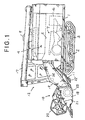
- Fig. 1
- is a side view of the combine.
- Fig. 2
- is a plan of the combine.
- Fig. 3
- is a rear view of driving system for hulling machine.
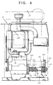
- Fig. 4
- is a cross-sectional view of an engine section.
- Fig. 5
- is a rear view of a clutch section.
- Fig. 6
- is a side view of the clutch section.
- Fig. 7
- is a plan of the clutch section.
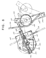
- Fig. 8
- is a partially enlarged rear view of the clutch section.
- Fig. 9
- is an illustration showing the whole engine driving system
- This invention will be described in more detail according to the attached drawing. In Figs. 1 and 2, vehicle floor 1 is mounted on
frame 3 which supports a couple of crawlers 2 on the left and the right sides of the combine. Ahulling machine 4 provided with ascrew type cylinder 5, a treatingdrum 6 and agrain sorter 7 is mounted on the vehicle floor 1.Grain tank 8 is designed to hold grains taking out from thehulling machine 4 by way ofgrain lifting pipe 9. Reaper 10 is designed to move up and down by means of hydraulic pressure cylinder 11 located below in front of thehulling machine 4. Operators'cabin 12 provided with theirseat 13 and an operation panel 14 is located before thegrain tank 8.Engine cover 15 enclosingengine 16 is located behind thegrain tank 8. Auger 17 is for taking out grains in thegrain tank 8. - The reaper 10 is provided with a couple of
headers 18 to push their front end into yet unreaped plants andfeeder house 19 is located behind the middle of the two headers to feed reaped plants to thehulling machine 4. Provided between theheaders 18 arereel 20 for taking in unreaped plants,first blade 21 andsecond blade 22, each capable of alternating motion and auger 23 for taking in reaped plants. Reaped plants taken from theheaders 18 is carried to thehulling machine 4 by means ofchain conveyer 24 inside thefeeder house 19. - Provided to on the right side of the hulling machine is second returning
pipe 25 to get yet unhulled grains back to thehulling machine 4 through the treatingdrum 6 in order to get them rehulled and resorted. - A working vehicle according to the invention, here a combine, is shown in Figs. 3 to 9. The combine comprises an
engine 16 for driving thehulling machine 4, and aradiator 108 for cooling the engine and asirocco fan 109 for cooling theradiator 108. These elements are arranged separately above and below in the hulling section. An output shaft 111 on aflywheel 110 side of theengine 16 is connected to acounter shaft 113 supported by a shaft bearing 112 on the right side of theengine 16 by using anadjustable joint 114. Pulleys 115, 116, 117, each fixed to thecounter shaft 113, are respectively connected to aninput pulley 119 of the hulling machine'sshaft 118, aninput pulley 122 of HST'sshaft 121 and aninput pulley 125 of aninput shaft 124 for driving anauger 123 by usingtransmission belts hulling machine 4, the crawlers 2 and thegrain tank 8. - The
hulling machine shaft 118 and the hullingmachine counter shaft 129 are connected to each other by usingreduction gears machine counter shaft 129 is connected to agearbox shaft 137 by usingpulleys belt 140, where thegearbox shaft 137 is connected to thecylinder shaft 133 with two stagespeed change gears gear 136, by which thecylinder 5 can be rotated in two high/low different speed. Meanwhile, 141 and 142 denote first and second conveyers of thehulling machine grain fan 184. - Additionally, a
tension roller clutch 145 is provided to on thetransmission belt 126 connecting thecounter shaft 113 and thehulling machine shaft 118, where thetension roller 145, which can be mounted on or dismounted from thebelt 126, is held by a roller bearingshaft 148 on one upper end of atension arm 147 of which the other lower end is pivotally fixed to abearing shaft 146 on the top of thebearing shaft base 112. On the other side of thebelt 126 on which tension is applied by thetension roller clutch 145, there is anelectric clutch motor 150 pivotally mounted on aplate 149. Ashaft 154 on the top of a rotatingarm 152 fixed to amotor shaft 151 and theshaft 155 on the top of aplate 153 unmovably fixed to on the top of thetension roller clutch 145 are connected to each other to jointly move by usingtension spring 156 and connectingrod 158 provided withguide rod 157. By this device, the tension roller clutch can be mounted on or dismounted from thebelt 126 by turning the motor in right or reverse direction. - The connecting
rod 158 which is laid in line with thetension spring 156 between the twoshafts rotating arm 152 when thetension roller clutch 145 is put on. In this device in order to prolong the belt's life, speed of the tension roller clutch from its touching the belt to its showing the maximum tension is designed to gradually slow down and action in response to on/off of the clutch is also designed to take place after a certain time interval. - The
motor shaft 151 is provided with abutting piece 159 so that the piece is butted againststoppers clutch motor 150 when the tension roller clutch is switched on or off, whereby the motor's position is limited. More specifically, thepiece 159 is butted against thestopper 160 so that thespring 156 and the connectingrod 158 can maintain their position over the fulcrum of themotor shaft 151 when the tension roller clutch is switched on. Also thepiece 159 is butted against thestopper 160 so that they can maintain their position when one side of thebelt 126 to which thetension roller clutch 145 is touched is so tensed as to get thetension arm 147 back to the off-position and another side of thebelt 126 is slackened by the engine stop (this gives thecylinder 5 inertia rotation), for example, while the tension roller clutch is being switched on, whereby their position is prevented from turning over the limited range. - As described above, compared to the conventional means in which the tension roller clutch and clutch lever are connected with wire to operate, this new system, in which the on/off switching of the tension roller clutch is conducted by the
clutch motor 150, can simplify the structure of the operation section, widely reduce manipulating power and make the tension roller clutch conduct exact on/off switching. - Also in this case, abrupt on/off switching of the
tension roller clutch 145 is avoided by putting a certain time interval before that switching by using the motor. That is, when the roller clutch is switched on, action before the belt is tensed by the tension roller clutch can be made gradually slow down by the semi-circle movement of therotating arm 152,in this way, the sudden clutch impact on thebelt 126 is avoided and the belt is prevented from breaking, whereby the life of the belt can be prolonged.
Claims (3)
- Working vehicle, comprising an engine (16) mounted on a machine floor, a tension roller clutch (145) provided generally in the middle point of a belt (126) for transmitting the driving force of said engine (16) to a working section, a clutch member (150) for said tension roller clutch (145) and a control means that makes the action of said tension roller clutch (145) caused by the input of said clutch member (150) fast until said tension roller clutch touches said belt and makes said action gradually slow after said tension roller clutch touches said belt.
- Working vehicle as claimed in claim 1, wherein a hulling machine (4) provided with a cylinder (5) and a grain sorter (7) is mounted on the vehicle floor (1) and thereby substantially forms a combine to crop grains.
- Working vehicle as claimed in claim 1, wherein said clutch member is an electric motor.
Applications Claiming Priority (10)
| Application Number | Priority Date | Filing Date | Title |
|---|---|---|---|
| JP24396893A JP3220826B2 (en) | 1993-09-03 | 1993-09-03 | Drive device for mobile farm machine |
| JP24396893 | 1993-09-03 | ||
| JP243968/93 | 1993-09-03 | ||
| JP22481093A JP2637683B2 (en) | 1993-09-09 | 1993-09-09 | Operation unit structure of work vehicle |
| JP22481093 | 1993-09-09 | ||
| JP224810/93 | 1993-09-09 | ||
| JP340899/93 | 1993-12-08 | ||
| JP34089993 | 1993-12-08 | ||
| JP34089993A JPH07155049A (en) | 1993-12-08 | 1993-12-08 | Combine threshing equipment |
| EP94113690A EP0641706B1 (en) | 1993-09-03 | 1994-09-01 | Working vehicle |
Related Parent Applications (2)
| Application Number | Title | Priority Date | Filing Date |
|---|---|---|---|
| EP94113690.5 Division | 1994-09-01 | ||
| EP94113690A Division EP0641706B1 (en) | 1993-09-03 | 1994-09-01 | Working vehicle |
Publications (2)
| Publication Number | Publication Date |
|---|---|
| EP0798196A1 EP0798196A1 (en) | 1997-10-01 |
| EP0798196B1 true EP0798196B1 (en) | 2002-02-06 |
Family
ID=27330955
Family Applications (2)
| Application Number | Title | Priority Date | Filing Date |
|---|---|---|---|
| EP94113690A Expired - Lifetime EP0641706B1 (en) | 1993-09-03 | 1994-09-01 | Working vehicle |
| EP97109840A Expired - Lifetime EP0798196B1 (en) | 1993-09-03 | 1994-09-01 | Working vehicle |
Family Applications Before (1)
| Application Number | Title | Priority Date | Filing Date |
|---|---|---|---|
| EP94113690A Expired - Lifetime EP0641706B1 (en) | 1993-09-03 | 1994-09-01 | Working vehicle |
Country Status (3)
| Country | Link |
|---|---|
| US (2) | US5584167A (en) |
| EP (2) | EP0641706B1 (en) |
| DE (2) | DE69429833T2 (en) |
Families Citing this family (15)
| Publication number | Priority date | Publication date | Assignee | Title |
|---|---|---|---|---|
| USD413907S (en) * | 1998-04-08 | 1999-09-14 | Furukawa Co., Ltd. | Crawler drill |
| JP3028481B1 (en) | 1998-12-16 | 2000-04-04 | ヤンマー農機株式会社 | Moving agricultural machine |
| US6370853B1 (en) * | 1999-10-13 | 2002-04-16 | Case Corporation | Drive system for corn header row units |
| KR100414418B1 (en) * | 2000-03-22 | 2004-01-07 | 가부시끼 가이샤 구보다 | Attitude controlling device for working vehicle |
| WO2002076716A1 (en) * | 2001-03-26 | 2002-10-03 | Boegli-Gravures S.A. | Device for treating flat material |
| DE10228866A1 (en) * | 2002-06-27 | 2004-01-29 | Claas Selbstfahrende Erntemaschinen Gmbh | Wind-screen device |
| US6672411B1 (en) * | 2002-10-18 | 2004-01-06 | Murray, Inc. | Control mechanism for a zero turning radius vehicle |
| CA2432097C (en) * | 2003-06-12 | 2008-04-15 | Jean-Guy Dube | Ventilation barrier |
| CA2479591A1 (en) * | 2004-09-27 | 2006-03-27 | Guy Gaudreault | Vehicle on multi-traction, modular caterpillar treads |
| RU2382542C1 (en) * | 2008-10-14 | 2010-02-27 | Волгоградская государственная сельскохозяйственная академия (ВГСХА) | Device of prior threshing of grain mainly for seeds |
| BE1021101B1 (en) * | 2013-07-12 | 2015-11-16 | Cnh Industrial Belgium Nv | CLEANING UNIT FOR A HARVESTER |
| BE1021105B1 (en) * | 2013-08-27 | 2016-01-12 | Cnh Industrial Belgium Nv | A CLEANING WHOLE FOR A HARVESTER |
| JP2017073984A (en) * | 2015-10-13 | 2017-04-20 | ヤンマー株式会社 | combine |
| CN106426098A (en) * | 2016-11-03 | 2017-02-22 | 哈尔滨工业大学 | Steel wire rope transmission and flexible tensioning mechanism |
| JP6910970B2 (en) * | 2018-01-10 | 2021-07-28 | 株式会社クボタ | Control device for work vehicles |
Family Cites Families (15)
| Publication number | Priority date | Publication date | Assignee | Title |
|---|---|---|---|---|
| US3625302A (en) * | 1969-05-12 | 1971-12-07 | Eaton Yale & Towne | Hydrostatic transmission control |
| US3727402A (en) * | 1971-06-30 | 1973-04-17 | Eaton Corp | Hydrostatic transmission speed and steering control system |
| DE2256609A1 (en) * | 1972-11-17 | 1974-05-30 | Zahnradfabrik Friedrichshafen | HYDROSTATIC TRAVEL DRIVE OF A HYDROSTATICALLY DRIVEN TRACKED VEHICLE |
| US4085812A (en) * | 1976-11-24 | 1978-04-25 | Sundstrand Corporation | Actuator system for dual path transmission |
| US4193315A (en) * | 1978-02-06 | 1980-03-18 | The Maytag Company | Belt drive system utilizing an adjustable idler mechanism |
| US4354420A (en) * | 1979-11-01 | 1982-10-19 | Caterpillar Tractor Co. | Fluid motor control system providing speed change by combination of displacement and flow control |
| DE8221573U1 (en) * | 1982-07-29 | 1986-01-09 | Claas Ohg, 4834 Harsewinkel | Self-propelled combine harvester |
| JPS5942812A (en) * | 1982-09-03 | 1984-03-09 | 株式会社クボタ | DC type combine harvester |
| FR2552568B1 (en) * | 1983-09-23 | 1986-04-04 | Noirot Yves | DEVICE FOR CONTROLLING THE MOVEMENT AND STEERING OF A HYDRAULICALLY DRIVEN VEHICLE |
| JPS61103047A (en) * | 1984-10-26 | 1986-05-21 | Makino Milling Mach Co Ltd | Transmission mechanism |
| JPH0620389B2 (en) * | 1987-09-16 | 1994-03-23 | 株式会社クボタ | Threshing unit sorting section |
| DD276616A1 (en) * | 1988-11-04 | 1990-03-07 | Fortschritt Veb K | CLEANING DEVICE FOR MAEHESCHESCHER |
| JPH02200113A (en) * | 1989-01-27 | 1990-08-08 | Kubota Ltd | Full culm input type combine harvester |
| JP2982213B2 (en) * | 1990-05-18 | 1999-11-22 | 井関農機株式会社 | Second sorter for threshing machine |
| JPH05133444A (en) * | 1991-11-11 | 1993-05-28 | Kubota Corp | Transmission gear of combine |
-
1994
- 1994-09-01 DE DE69429833T patent/DE69429833T2/en not_active Expired - Fee Related
- 1994-09-01 EP EP94113690A patent/EP0641706B1/en not_active Expired - Lifetime
- 1994-09-01 DE DE69418951T patent/DE69418951T2/en not_active Expired - Lifetime
- 1994-09-01 EP EP97109840A patent/EP0798196B1/en not_active Expired - Lifetime
- 1994-09-02 US US08/299,621 patent/US5584167A/en not_active Expired - Lifetime
-
1996
- 1996-10-01 US US08/722,579 patent/US5699656A/en not_active Expired - Lifetime
Also Published As
| Publication number | Publication date |
|---|---|
| DE69429833D1 (en) | 2002-03-21 |
| DE69429833T2 (en) | 2002-09-12 |
| EP0641706A2 (en) | 1995-03-08 |
| EP0798196A1 (en) | 1997-10-01 |
| DE69418951T2 (en) | 1999-11-11 |
| EP0641706B1 (en) | 1999-06-09 |
| DE69418951D1 (en) | 1999-07-15 |
| US5699656A (en) | 1997-12-23 |
| US5584167A (en) | 1996-12-17 |
| EP0641706A3 (en) | 1995-05-10 |
Similar Documents
| Publication | Publication Date | Title |
|---|---|---|
| JP3013036B2 (en) | Combine | |
| EP0097987B1 (en) | Drive tensioning apparatus | |
| CA1178158A (en) | Harvester threshing rotor drive having variable speed belt drive and clutching means | |
| US5699656A (en) | Agricultural combine | |
| US5393270A (en) | Transmitting rotary power | |
| WO2014077134A1 (en) | Combine harvester | |
| EP0097986B1 (en) | Torque sensing drive | |
| JPH0661180B2 (en) | Power transmission device for work vehicle | |
| US5679083A (en) | Wheel driving device for loader | |
| JP3967222B2 (en) | Combine | |
| JP3371438B2 (en) | Combine transmission | |
| US3498398A (en) | Windrower drive and control therefor | |
| KR102821430B1 (en) | Combine | |
| JP3220826B2 (en) | Drive device for mobile farm machine | |
| JP2014212745A (en) | Combine | |
| JP2556180Y2 (en) | Combine | |
| JP3252260B2 (en) | Combine | |
| JPS5928912Y2 (en) | Power transmission device in combine harvester | |
| KR20160089258A (en) | Combine having single normal and reverse rotation device using a rink mechanism | |
| JP3013035B2 (en) | Combine | |
| JP6183485B2 (en) | Combine | |
| JP2571038Y2 (en) | Combine harvesting clutch device | |
| JP2587617Y2 (en) | Combine pretreatment gearbox | |
| JP2707090B2 (en) | Combine speed controller | |
| JP6070813B2 (en) | Combine |
Legal Events
| Date | Code | Title | Description |
|---|---|---|---|
| PUAI | Public reference made under article 153(3) epc to a published international application that has entered the european phase |
Free format text: ORIGINAL CODE: 0009012 |
|
| AC | Divisional application: reference to earlier application |
Ref document number: 641706 Country of ref document: EP |
|
| AK | Designated contracting states |
Kind code of ref document: A1 Designated state(s): BE DE FR GB |
|
| 17P | Request for examination filed |
Effective date: 19971215 |
|
| 17Q | First examination report despatched |
Effective date: 19990519 |
|
| GRAG | Despatch of communication of intention to grant |
Free format text: ORIGINAL CODE: EPIDOS AGRA |
|
| GRAG | Despatch of communication of intention to grant |
Free format text: ORIGINAL CODE: EPIDOS AGRA |
|
| GRAH | Despatch of communication of intention to grant a patent |
Free format text: ORIGINAL CODE: EPIDOS IGRA |
|
| GRAH | Despatch of communication of intention to grant a patent |
Free format text: ORIGINAL CODE: EPIDOS IGRA |
|
| GRAA | (expected) grant |
Free format text: ORIGINAL CODE: 0009210 |
|
| REG | Reference to a national code |
Ref country code: GB Ref legal event code: IF02 |
|
| AC | Divisional application: reference to earlier application |
Ref document number: 641706 Country of ref document: EP |
|
| AK | Designated contracting states |
Kind code of ref document: B1 Designated state(s): BE DE FR GB |
|
| PG25 | Lapsed in a contracting state [announced via postgrant information from national office to epo] |
Ref country code: BE Free format text: LAPSE BECAUSE OF FAILURE TO SUBMIT A TRANSLATION OF THE DESCRIPTION OR TO PAY THE FEE WITHIN THE PRESCRIBED TIME-LIMIT Effective date: 20020206 |
|
| REF | Corresponds to: |
Ref document number: 69429833 Country of ref document: DE Date of ref document: 20020321 |
|
| ET | Fr: translation filed | ||
| PLBE | No opposition filed within time limit |
Free format text: ORIGINAL CODE: 0009261 |
|
| STAA | Information on the status of an ep patent application or granted ep patent |
Free format text: STATUS: NO OPPOSITION FILED WITHIN TIME LIMIT |
|
| 26N | No opposition filed |
Effective date: 20021107 |
|
| PGFP | Annual fee paid to national office [announced via postgrant information from national office to epo] |
Ref country code: GB Payment date: 20080827 Year of fee payment: 15 |
|
| PGFP | Annual fee paid to national office [announced via postgrant information from national office to epo] |
Ref country code: DE Payment date: 20080925 Year of fee payment: 15 |
|
| PGFP | Annual fee paid to national office [announced via postgrant information from national office to epo] |
Ref country code: FR Payment date: 20080922 Year of fee payment: 15 |
|
| GBPC | Gb: european patent ceased through non-payment of renewal fee |
Effective date: 20090901 |
|
| REG | Reference to a national code |
Ref country code: FR Ref legal event code: ST Effective date: 20100531 |
|
| PG25 | Lapsed in a contracting state [announced via postgrant information from national office to epo] |
Ref country code: FR Free format text: LAPSE BECAUSE OF NON-PAYMENT OF DUE FEES Effective date: 20090930 Ref country code: DE Free format text: LAPSE BECAUSE OF NON-PAYMENT OF DUE FEES Effective date: 20100401 |
|
| PG25 | Lapsed in a contracting state [announced via postgrant information from national office to epo] |
Ref country code: GB Free format text: LAPSE BECAUSE OF NON-PAYMENT OF DUE FEES Effective date: 20090901 |