EP0798184A1 - Drive head for a motor vehicle windscreen wiper - Google Patents
Drive head for a motor vehicle windscreen wiper Download PDFInfo
- Publication number
- EP0798184A1 EP0798184A1 EP97301899A EP97301899A EP0798184A1 EP 0798184 A1 EP0798184 A1 EP 0798184A1 EP 97301899 A EP97301899 A EP 97301899A EP 97301899 A EP97301899 A EP 97301899A EP 0798184 A1 EP0798184 A1 EP 0798184A1
- Authority
- EP
- European Patent Office
- Prior art keywords
- head
- wiper
- drive
- shape
- side walls
- Prior art date
- Legal status (The legal status is an assumption and is not a legal conclusion. Google has not performed a legal analysis and makes no representation as to the accuracy of the status listed.)
- Granted
Links
- 239000002184 metal Substances 0.000 claims abstract description 15
- 230000015572 biosynthetic process Effects 0.000 claims description 3
- 239000000463 material Substances 0.000 claims description 3
- 241000277275 Oncorhynchus mykiss Species 0.000 claims description 2
- 230000037237 body shape Effects 0.000 claims description 2
- 238000005728 strengthening Methods 0.000 claims description 2
- 229910000831 Steel Inorganic materials 0.000 abstract description 2
- 239000010959 steel Substances 0.000 abstract description 2
- 238000004140 cleaning Methods 0.000 description 1
- 238000012423 maintenance Methods 0.000 description 1
- 239000003973 paint Substances 0.000 description 1
- 230000001681 protective effect Effects 0.000 description 1
Images


Classifications
-
- B—PERFORMING OPERATIONS; TRANSPORTING
- B60—VEHICLES IN GENERAL
- B60S—SERVICING, CLEANING, REPAIRING, SUPPORTING, LIFTING, OR MANOEUVRING OF VEHICLES, NOT OTHERWISE PROVIDED FOR
- B60S1/00—Cleaning of vehicles
- B60S1/02—Cleaning windscreens, windows or optical devices
- B60S1/04—Wipers or the like, e.g. scrapers
- B60S1/32—Wipers or the like, e.g. scrapers characterised by constructional features of wiper blade arms or blades
- B60S1/34—Wiper arms; Mountings therefor
- B60S1/3425—Constructional aspects of the arm
- B60S1/3436—Mounting heads
- B60S1/344—Flat-type mounting heads
-
- B—PERFORMING OPERATIONS; TRANSPORTING
- B60—VEHICLES IN GENERAL
- B60S—SERVICING, CLEANING, REPAIRING, SUPPORTING, LIFTING, OR MANOEUVRING OF VEHICLES, NOT OTHERWISE PROVIDED FOR
- B60S1/00—Cleaning of vehicles
- B60S1/02—Cleaning windscreens, windows or optical devices
- B60S1/04—Wipers or the like, e.g. scrapers
- B60S1/32—Wipers or the like, e.g. scrapers characterised by constructional features of wiper blade arms or blades
- B60S1/34—Wiper arms; Mountings therefor
- B60S1/3425—Constructional aspects of the arm
- B60S1/3445—Joints between elements
- B60S1/3459—Joints between elements the element being a mounting head and a shaft
-
- B—PERFORMING OPERATIONS; TRANSPORTING
- B60—VEHICLES IN GENERAL
- B60S—SERVICING, CLEANING, REPAIRING, SUPPORTING, LIFTING, OR MANOEUVRING OF VEHICLES, NOT OTHERWISE PROVIDED FOR
- B60S1/00—Cleaning of vehicles
- B60S1/02—Cleaning windscreens, windows or optical devices
- B60S1/04—Wipers or the like, e.g. scrapers
- B60S1/32—Wipers or the like, e.g. scrapers characterised by constructional features of wiper blade arms or blades
- B60S1/34—Wiper arms; Mountings therefor
- B60S1/3463—Means to press blade onto screen
- B60S1/3465—Means to press blade onto screen with coil springs
- B60S1/3468—Mountings therefor
Definitions
- the drive head of a windscreen wiper assembly is designed at one end to be mounted onto a drive shaft of a drive motor and at the other end to provide a pivotal mounting for a wiper arm, enabling the wiper arm to be lifted away from the windscreen for cleaning or maintenance.
- the connection of the drive shaft onto the head is by means of a DIN taper at the tip of the drive shaft which fits into a complementarily shaped recess in the head.
- the head is conventionally cast from metal and thus provides a very robust location for the tapered head of the drive shaft.
- a windscreen wiper drive head pressed from a sheet of metal to define a U-shaped cross-section forming two side walls extending for substantially the length of the head and a joining wall therebetween, a locating portion of the joining wall towards one end of the head being deformed to create a projection defining a tapered passageway for receipt of a DIN tapered drive shaft head, and the side walls being formed towards the other end of the head to define aligned bearing holes for receipt therein of a pivot of a wiper arm retainer.
- the pressed out tapered passageway forms a suitably robust mounting for the DIN tapered drive shaft head and the U-shaped cross-section of the metal head provides suitable strength.
- the projection from the joining wall can extend inwardly of the U-shape of the pressed metal sheet.
- this projection could extend outwardly of the U-shape of the pressed steel head. In the latter case it is preferred that the projection should be located within a surrounding part of the joining wall which is recessed into the U-shape of the pressed metal sheet.
- the opening to the U-shape of the pressed metal sheet could be closed by a cover which is snapped into place between the two side walls.
- the joining wall is deformed to create a longitudinal strengthening rib.
- This rib can also improve the styling of the drive head and provide an area for a Trade Mark or the like to be impressed.
- the drive head can be shaped such that the U-shaped formation of the pressed metal sheet is also formed to define an angular shape from one end to the other and/or a sideways offset from one end to the other, and/or a twisted body shape.
- the end of the joining wall at the other end of the head should be formed with a notch to allow for movement of a biassing spring or locating arm thereof, as a wiper arm mounted on the drive head is pivoted relative to the drive head.
- the other end of the head incorporates a mounting slot to receive a hook at the end of a biassing spring, the slot being formed by cutting out part of a plate projecting from one of the side walls and folding back the cut material for the hook.
- the drive head for a windscreen wiper assembly as shown in Figures 1 and 2 is pressed from sheet steel to define two side walls 1 and 2 and adjoining top wall 3. At one end holes 4 are provided in the side walls 1 and 2 to receive a pivot pin for a wiper arm retainer which will be located onto the drive head. At the other end the sheet metal is deformed to create a conical projection 5 which has a DIN taper equivalent to that of the head of a drive shaft from the windscreen wiper motor.
- the drive shaft 6 is shown in Figure 3 and has a splined conical drive head 7 and a screw threaded end 8.
- the washer 10 has a passageway 11 which is also formed to the same DIN taper as the head 7 and of the projection 5.
- the drive head can be deformed to any desired shape and in particular can incorporate a longitudinal rib 12 which gives added strength to the structure. It also provides an area on which printed information, Trade Marks, etc can be impressed or stamped. In this version of drive head the projection 5 is located in a surrounding depression 13 so that the locating nut 9 will be hidden away.
- FIGs 6 and 7 has a more pronounced upstanding rib 14 and the side walls 1 and 2 are of a generally sinuous shape for strength and pleasing appearance.
- a shaped part 15 of the side wall 2 is bent over to form a locating plate to receive the end of a wiper arm retainer spring.
- a notch 16 is pressed out of the plate 15 and the pressed-out material is then folded back at 17 to provide a double thickness location (as can be seen in Figure 8) for the end of the spring. This resists tearing of the metal of the plate which might otherwise occur.
- a notch 18 is ideally formed at one end of the head.
- the plate 15 extends across from the side wall 1 to the side wall 2 so that it can rest on the side wall 2. Preferably however the plate 15 will stop short of the other side wall and the position of the plate relative to the pivot axis of the holes 4 allows for variability of the spring load. The loading characteristics also depend upon the position of the slot 16 in the plate 15 relative to the axis of the pivot holes 4.
- FIG 10. Another type of formation for the projection 5 is shown in Figure 10.
- the projection 5 extends up between the two side walls 1 and 2 rather than projecting outwardly of the body of the drive head.
- a protective cap can be snapped in place, such as is shown in Figure 11 at 19.
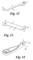
- Figures 12 and 13 show the geometry for a drive head of the type as illustrated partly in Figure 10. Other variations in shape may be created in the pressed sheet including sideways offsetting from one end to the other, if desired.
- Figure 14 illustrates how the body of the drive head can be twisted so that the axis 20 of the pivot holes 4 is rotated about the centre line 21.
- the bearings mounting is provided by a pair of "top hat” bearings 22 which fit into the passageways 3. These bearings 22 provide the mounting for the pivot pin which will pass through the drive head 1 and a wiper arm which will be located outside the drive head 1.
- the enlarged heads 23 of the bearings 22 space the wiper arm away from the drive head 1 and thus prevent damage to paint work when the two parts move relative to one another.
- a locating pin 24 is provided for a hook at the end of a locating spring. The hook at the end of the spring will be held centrally by a pair of side wings 25 of the drive head 1.
Landscapes
- Engineering & Computer Science (AREA)
- Mechanical Engineering (AREA)
- Connection Of Plates (AREA)
- Pivots And Pivotal Connections (AREA)
- Body Structure For Vehicles (AREA)
Abstract
Description
- The drive head of a windscreen wiper assembly is designed at one end to be mounted onto a drive shaft of a drive motor and at the other end to provide a pivotal mounting for a wiper arm, enabling the wiper arm to be lifted away from the windscreen for cleaning or maintenance. The connection of the drive shaft onto the head is by means of a DIN taper at the tip of the drive shaft which fits into a complementarily shaped recess in the head. The head is conventionally cast from metal and thus provides a very robust location for the tapered head of the drive shaft.
- According to the present invention there is provided a windscreen wiper drive head pressed from a sheet of metal to define a U-shaped cross-section forming two side walls extending for substantially the length of the head and a joining wall therebetween, a locating portion of the joining wall towards one end of the head being deformed to create a projection defining a tapered passageway for receipt of a DIN tapered drive shaft head, and the side walls being formed towards the other end of the head to define aligned bearing holes for receipt therein of a pivot of a wiper arm retainer.
- With this design the pressed out tapered passageway forms a suitably robust mounting for the DIN tapered drive shaft head and the U-shaped cross-section of the metal head provides suitable strength.
- The projection from the joining wall can extend inwardly of the U-shape of the pressed metal sheet. Alternatively this projection could extend outwardly of the U-shape of the pressed steel head. In the latter case it is preferred that the projection should be located within a surrounding part of the joining wall which is recessed into the U-shape of the pressed metal sheet.
- If desired, especially if the joining wall is to form a lower face of the drive head (in use) then the opening to the U-shape of the pressed metal sheet could be closed by a cover which is snapped into place between the two side walls.
- Preferably the joining wall is deformed to create a longitudinal strengthening rib. This rib can also improve the styling of the drive head and provide an area for a Trade Mark or the like to be impressed. If desired the drive head can be shaped such that the U-shaped formation of the pressed metal sheet is also formed to define an angular shape from one end to the other and/or a sideways offset from one end to the other, and/or a twisted body shape.
- It is preferred that the end of the joining wall at the other end of the head should be formed with a notch to allow for movement of a biassing spring or locating arm thereof, as a wiper arm mounted on the drive head is pivoted relative to the drive head.
- Ideally the other end of the head incorporates a mounting slot to receive a hook at the end of a biassing spring, the slot being formed by cutting out part of a plate projecting from one of the side walls and folding back the cut material for the hook.
- The invention may be performed in various ways and various embodiments will now be described, by way of example, with reference to the accompanying drawings, in which:-
- Figure 1 is a plan view of a windscreen wiper drive head of this invention;
- Figure 2 is an underneath plan view of the drive head of Figure 1;
- Figure 3 is a cross-section through a portion of the drive head of Figures 1 and 2;
- Figure 4 is a perspective view of an alternative form of drive head of the invention;
- Figure 5 is a cross-section on the line A-A through part of the drive head of Figure 4;
- Figures 6 and 7 are perspective and underneath plan views respectively of a third embodiment of the invention;
- Figure 8 is a view on arrow B of Figure 7;
- Figure 9 is a detail of a modified end section of a drive head of the invention;
- Figure 10 is a top view of part of another alternative form of drive head of the invention;
- Figure 11 illustrates a cover for the drive head of Figure 10;
- Figures 12 and 13 are side and perspective plan views of the embodiment of the invention incorporating the feature of Figure 10;
- Figure 14 shows a further example of the shape of a drive head of the invention; and
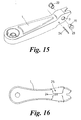
- Figures 15 and 16 are perspective and underneath views respectively of yet another form of drive head of the invention.
- The drive head for a windscreen wiper assembly as shown in Figures 1 and 2 is pressed from sheet steel to define two
side walls top wall 3. At oneend holes 4 are provided in theside walls conical projection 5 which has a DIN taper equivalent to that of the head of a drive shaft from the windscreen wiper motor. Thedrive shaft 6 is shown in Figure 3 and has a splinedconical drive head 7 and a screw threaded end 8. When thetapered head 7 is located into theprojection 5, anut 9 is screwed onto the threaded end 8 to drive awasher 10 into engagement with theprojection 5 so as to lock thedrive shaft 6 securely to the drive head. Thewasher 10 has apassageway 11 which is also formed to the same DIN taper as thehead 7 and of theprojection 5. - As shown in Figures 4 and 5 the drive head can be deformed to any desired shape and in particular can incorporate a
longitudinal rib 12 which gives added strength to the structure. It also provides an area on which printed information, Trade Marks, etc can be impressed or stamped. In this version of drive head theprojection 5 is located in a surroundingdepression 13 so that the locatingnut 9 will be hidden away. - The embodiment shown in Figures 6 and 7 has a more pronounced
upstanding rib 14 and theside walls shaped part 15 of theside wall 2 is bent over to form a locating plate to receive the end of a wiper arm retainer spring. Anotch 16 is pressed out of theplate 15 and the pressed-out material is then folded back at 17 to provide a double thickness location (as can be seen in Figure 8) for the end of the spring. This resists tearing of the metal of the plate which might otherwise occur. As shown in Figure 4 anotch 18 is ideally formed at one end of the head. This will receive the end of the spring locating arm when the wiper arm retainer is pivoted up relative to the drive head. A suitable shape for thenotch 18 is also shown in the arrangement for Figure 9. In this version also theplate 15 extends across from theside wall 1 to theside wall 2 so that it can rest on theside wall 2. Preferably however theplate 15 will stop short of the other side wall and the position of the plate relative to the pivot axis of theholes 4 allows for variability of the spring load. The loading characteristics also depend upon the position of theslot 16 in theplate 15 relative to the axis of thepivot holes 4. - Another type of formation for the
projection 5 is shown in Figure 10. In this case theprojection 5 extends up between the twoside walls axis 20 of thepivot holes 4 is rotated about thecentre line 21. - In the arrangement shown in Figures 15 and 16 the bearings mounting is provided by a pair of "top hat"
bearings 22 which fit into thepassageways 3. Thesebearings 22 provide the mounting for the pivot pin which will pass through thedrive head 1 and a wiper arm which will be located outside thedrive head 1. The enlargedheads 23 of thebearings 22 space the wiper arm away from thedrive head 1 and thus prevent damage to paint work when the two parts move relative to one another. In this arrangement a locatingpin 24 is provided for a hook at the end of a locating spring. The hook at the end of the spring will be held centrally by a pair ofside wings 25 of thedrive head 1.
Claims (10)
- A windscreen wiper drive head pressed from a sheet of metal to define a U-shaped cross-section forming two side walls extending for substantially the length of the head and a joining wall therebetween, a locating portion of the joining wall towards one end of the head being deformed to create a projection defining a tapered passageway for receipt of a DIN tapered drive shaft head, and the side walls being formed towards the other end of the head to define aligned bearing holes for receipt therein of a pivot of a wiper arm retainer.
- A wiper head according to Claim 1, wherein said projection extends inwardly of the U-shape of the pressed metal sheet.
- A wiper head according to Claim 1, wherein said projection extends outwardly of the U-shape of the pressed steel head.
- A wiper head according to Claim 3, wherein said projection is located within a surrounding part of the joining wall which is recessed into the U-shape of the pressed metal sheet.
- A wiper head according to any one of Claims 1 to 4, wherein the opening to the U-shape of the pressed metal sheet is closed by a cover which is snapped into place between the two side walls.
- A wiper head according to any one of Claims 1 to 5, wherein the joining wall is deformed to create a longitudinal strengthening rib.
- A wiper head according to any one of Claims 1 to 6, wherein the U-shaped formation of the pressed metal sheet is also formed to define an angular shape from one end to the other and/or a sideways offset from one end to the other, and/or a twisted body shape.
- A wiper head according to any one of Claims 1 to 7, wherein the end of the joining wall at the other end of the head is formed with a notch to allow for movement of a biassing spring or locating arm thereof, as a wiper arm mounted on the drive head is pivoted relative to the drive head.
- A wiper head according to any one of Claims 1 to 8, wherein the other end of the head incorporates a mounting slot to receive a hook at the end of a biassing spring, the slot being formed by cutting out part of a plate projecting from one of the side walls and folding back the cut material below the plate to create a robust location bearing point for the hook.
- A wiper head of a form substantially as herein described with reference to the accompanying drawings.
Applications Claiming Priority (2)
| Application Number | Priority Date | Filing Date | Title |
|---|---|---|---|
| GB9606148 | 1996-03-23 | ||
| GBGB9606148.6A GB9606148D0 (en) | 1996-03-23 | 1996-03-23 | Improvement relating to windscreen wipers heads |
Publications (2)
| Publication Number | Publication Date |
|---|---|
| EP0798184A1 true EP0798184A1 (en) | 1997-10-01 |
| EP0798184B1 EP0798184B1 (en) | 2001-02-07 |
Family
ID=10790907
Family Applications (1)
| Application Number | Title | Priority Date | Filing Date |
|---|---|---|---|
| EP97301899A Expired - Lifetime EP0798184B1 (en) | 1996-03-23 | 1997-03-20 | Drive head for a motor vehicle windscreen wiper |
Country Status (4)
| Country | Link |
|---|---|
| EP (1) | EP0798184B1 (en) |
| DE (1) | DE69704035T2 (en) |
| GB (2) | GB9606148D0 (en) |
| ZA (1) | ZA972420B (en) |
Cited By (5)
| Publication number | Priority date | Publication date | Assignee | Title |
|---|---|---|---|---|
| WO2002012034A1 (en) * | 2000-08-10 | 2002-02-14 | Robert Bosch Gmbh | Fixing piece for a windscreen wiper |
| WO2004000615A1 (en) * | 2002-06-21 | 2003-12-31 | Robert Bosch Gmbh | Fastening element for the wiper arm of a vehicle windshield wiper |
| WO2004000614A1 (en) * | 2002-06-25 | 2003-12-31 | Robert Bosch Gmbh | Window wiper for vehicle windows |
| WO2004018270A1 (en) * | 2002-08-03 | 2004-03-04 | Robert Bosch Gmbh | Reinforcing element for a fixing part of a wiper arm |
| EP1495929A1 (en) * | 2003-07-11 | 2005-01-12 | Robert Bosch Gmbh | Wiper arm, especially for a motor vehicle |
Families Citing this family (4)
| Publication number | Priority date | Publication date | Assignee | Title |
|---|---|---|---|---|
| GB9905666D0 (en) * | 1999-03-12 | 1999-05-05 | Trico Ltd | Improvements relating to wiper windscreen heads |
| DE102005044761A1 (en) * | 2005-09-20 | 2007-03-29 | Robert Bosch Gmbh | Sheet metal fastening part |
| DE102005062773A1 (en) * | 2005-12-28 | 2007-07-05 | Robert Bosch Gmbh | Sheet metal mounting part for mounting of windscreen wiper in wiping system, has two mounting units connected with each other by positive-fit or force-fit sheet metal connection to provide closed cross section in area of part |
| DE102009027005A1 (en) * | 2009-06-17 | 2010-12-23 | Robert Bosch Gmbh | Fastening element for receiving a wiper arm |
Citations (6)
| Publication number | Priority date | Publication date | Assignee | Title |
|---|---|---|---|---|
| FR2543896A1 (en) * | 1983-04-05 | 1984-10-12 | Marchal Equip Auto | SPRING COVER FOR WINDSCREEN WIPER AND WIPER PROVIDED WITH THIS SPRING COVER |
| FR2550147A2 (en) * | 1982-04-02 | 1985-02-08 | Marchal Equip Auto | MATRIXED ASSEMBLY HEAD OF A WIPER ELEMENT, ITS MANUFACTURING METHOD AND WIPER ELEMENT COMPRISING SAME |
| DE3515329A1 (en) * | 1984-04-27 | 1985-12-19 | Equipements Automobiles Marchal, Issy-Les-Moulineaux, Hauts-de-Seine | Punched connecting head for a window wiper element, method for manufacturing it and a window wiper element having this head |
| DE3926714A1 (en) * | 1989-08-12 | 1991-02-14 | Swf Auto Electric Gmbh | Lacquered metal parts for windscreen wipers - are mfd. by stamping, pressing and lacquering parts attached to one another |
| DE4322297A1 (en) * | 1993-07-05 | 1995-01-12 | Teves Gmbh Alfred | Drive crank of a windshield wiper system |
| DE4331602A1 (en) * | 1993-09-17 | 1995-03-23 | Teves Gmbh Alfred | Wiper arm |
Family Cites Families (2)
| Publication number | Priority date | Publication date | Assignee | Title |
|---|---|---|---|---|
| DE1979505U (en) * | 1967-11-11 | 1968-02-22 | Rau Swf Autozubehoer | FASTENING PART FOR WIPER WIPER. |
| DE3006188A1 (en) * | 1980-02-19 | 1981-08-20 | SWF-Spezialfabrik für Autozubehör Gustav Rau GmbH, 7120 Bietigheim-Bissingen | WIPER ARM, ESPECIALLY FOR MOTOR VEHICLES AND METHOD FOR THE PRODUCTION THEREOF |
-
1996
- 1996-03-23 GB GBGB9606148.6A patent/GB9606148D0/en active Pending
-
1997
- 1997-03-20 ZA ZA9702420A patent/ZA972420B/en unknown
- 1997-03-20 GB GB9705773A patent/GB2311209B/en not_active Expired - Fee Related
- 1997-03-20 EP EP97301899A patent/EP0798184B1/en not_active Expired - Lifetime
- 1997-03-20 DE DE69704035T patent/DE69704035T2/en not_active Expired - Fee Related
Patent Citations (6)
| Publication number | Priority date | Publication date | Assignee | Title |
|---|---|---|---|---|
| FR2550147A2 (en) * | 1982-04-02 | 1985-02-08 | Marchal Equip Auto | MATRIXED ASSEMBLY HEAD OF A WIPER ELEMENT, ITS MANUFACTURING METHOD AND WIPER ELEMENT COMPRISING SAME |
| FR2543896A1 (en) * | 1983-04-05 | 1984-10-12 | Marchal Equip Auto | SPRING COVER FOR WINDSCREEN WIPER AND WIPER PROVIDED WITH THIS SPRING COVER |
| DE3515329A1 (en) * | 1984-04-27 | 1985-12-19 | Equipements Automobiles Marchal, Issy-Les-Moulineaux, Hauts-de-Seine | Punched connecting head for a window wiper element, method for manufacturing it and a window wiper element having this head |
| DE3926714A1 (en) * | 1989-08-12 | 1991-02-14 | Swf Auto Electric Gmbh | Lacquered metal parts for windscreen wipers - are mfd. by stamping, pressing and lacquering parts attached to one another |
| DE4322297A1 (en) * | 1993-07-05 | 1995-01-12 | Teves Gmbh Alfred | Drive crank of a windshield wiper system |
| DE4331602A1 (en) * | 1993-09-17 | 1995-03-23 | Teves Gmbh Alfred | Wiper arm |
Cited By (12)
| Publication number | Priority date | Publication date | Assignee | Title |
|---|---|---|---|---|
| WO2002012034A1 (en) * | 2000-08-10 | 2002-02-14 | Robert Bosch Gmbh | Fixing piece for a windscreen wiper |
| RU2269438C2 (en) * | 2000-08-10 | 2006-02-10 | Роберт Бош Гмбх | Fastening part of windshield wipper arm and method of its manufacture (versions) |
| US7036181B2 (en) | 2000-08-10 | 2006-05-02 | Robert Bosch Gmbh | Fixing piece for a windscreen wiper |
| CZ297238B6 (en) * | 2000-08-10 | 2006-10-11 | Robert Bosch Gmbh | Fixing piece for windscreen wiper and process for producing thereof |
| KR100782873B1 (en) * | 2000-08-10 | 2007-12-06 | 로베르트 보쉬 게엠베하 | Fixture for windscreen wipers |
| WO2004000615A1 (en) * | 2002-06-21 | 2003-12-31 | Robert Bosch Gmbh | Fastening element for the wiper arm of a vehicle windshield wiper |
| US7076829B2 (en) | 2002-06-21 | 2006-07-18 | Robert Bosch Gmbh | Fastening element for the wiper arm of a vehicle windshield wiper |
| WO2004000614A1 (en) * | 2002-06-25 | 2003-12-31 | Robert Bosch Gmbh | Window wiper for vehicle windows |
| CN100358758C (en) * | 2002-06-25 | 2008-01-02 | 罗伯特-博希股份公司 | Windshield wipers |
| WO2004018270A1 (en) * | 2002-08-03 | 2004-03-04 | Robert Bosch Gmbh | Reinforcing element for a fixing part of a wiper arm |
| DE10235565B4 (en) * | 2002-08-03 | 2014-05-08 | Robert Bosch Gmbh | Reinforcement element for a fastening part |
| EP1495929A1 (en) * | 2003-07-11 | 2005-01-12 | Robert Bosch Gmbh | Wiper arm, especially for a motor vehicle |
Also Published As
| Publication number | Publication date |
|---|---|
| GB9606148D0 (en) | 1996-05-29 |
| EP0798184B1 (en) | 2001-02-07 |
| DE69704035T2 (en) | 2001-08-02 |
| GB2311209A (en) | 1997-09-24 |
| ZA972420B (en) | 1997-08-25 |
| GB9705773D0 (en) | 1997-05-07 |
| GB2311209B (en) | 1999-04-21 |
| DE69704035D1 (en) | 2001-03-15 |
Similar Documents
| Publication | Publication Date | Title |
|---|---|---|
| US6810555B2 (en) | Wiper arm, especially for a windscreen-wiping device of a motor vehicle | |
| US6718596B2 (en) | Reversible door hinge | |
| US5920963A (en) | Rope fastener | |
| EP0798184A1 (en) | Drive head for a motor vehicle windscreen wiper | |
| US7617571B2 (en) | Pin-less assist grip handle assembly | |
| US20070289079A1 (en) | Wiper Blade | |
| WO1998033679A3 (en) | Fixing element | |
| US6178588B1 (en) | Device for linking a wiper blade to a wiper arm | |
| US4949422A (en) | Connecting member for a wiper blade and a wiper arm | |
| EP0964973B1 (en) | A motor vehicle having a support stay for the bonnet | |
| CN1083781C (en) | Windshield wiper arm and method of manufacture | |
| GB2311461A (en) | Mounting hooked springs on thin plates | |
| US20030145413A1 (en) | Wiper arm, in particular for a motor vehicle and method for producing the same | |
| JP2001301580A (en) | Cover body for arm head of wiper device | |
| JPH06505459A (en) | Wiper arm especially for wiping car windshields | |
| US5325979A (en) | Fuel erroneous supply prevention shutter | |
| JP4267537B2 (en) | Wiper blade | |
| JP7658569B2 (en) | Wiper arm clamp mounting structure | |
| US5462195A (en) | Device for mounting a handle to a pan body | |
| KR0129704Y1 (en) | Retractable Handlebar | |
| JP3197479B2 (en) | Operating device for latch device in drawer | |
| JPH06146699A (en) | Arm type hinge of trunk lid for automobile with temporary stop function | |
| JP2001328510A (en) | Wiper arm | |
| JPH0620856Y2 (en) | Striker mounting structure for automobile glove box lock | |
| JP3886430B2 (en) | Vehicle wind direction adjusting device |
Legal Events
| Date | Code | Title | Description |
|---|---|---|---|
| PUAI | Public reference made under article 153(3) epc to a published international application that has entered the european phase |
Free format text: ORIGINAL CODE: 0009012 |
|
| AK | Designated contracting states |
Kind code of ref document: A1 Designated state(s): BE DE ES FR |
|
| 17P | Request for examination filed |
Effective date: 19980205 |
|
| 17Q | First examination report despatched |
Effective date: 19990505 |
|
| GRAG | Despatch of communication of intention to grant |
Free format text: ORIGINAL CODE: EPIDOS AGRA |
|
| GRAG | Despatch of communication of intention to grant |
Free format text: ORIGINAL CODE: EPIDOS AGRA |
|
| GRAH | Despatch of communication of intention to grant a patent |
Free format text: ORIGINAL CODE: EPIDOS IGRA |
|
| GRAH | Despatch of communication of intention to grant a patent |
Free format text: ORIGINAL CODE: EPIDOS IGRA |
|
| GRAA | (expected) grant |
Free format text: ORIGINAL CODE: 0009210 |
|
| AK | Designated contracting states |
Kind code of ref document: B1 Designated state(s): BE DE ES FR |
|
| REF | Corresponds to: |
Ref document number: 69704035 Country of ref document: DE Date of ref document: 20010315 |
|
| PGFP | Annual fee paid to national office [announced via postgrant information from national office to epo] |
Ref country code: ES Payment date: 20010328 Year of fee payment: 5 |
|
| ET | Fr: translation filed | ||
| PG25 | Lapsed in a contracting state [announced via postgrant information from national office to epo] |
Ref country code: ES Free format text: LAPSE BECAUSE OF FAILURE TO SUBMIT A TRANSLATION OF THE DESCRIPTION OR TO PAY THE FEE WITHIN THE PRESCRIBED TIME-LIMIT Effective date: 20010829 |
|
| PLBE | No opposition filed within time limit |
Free format text: ORIGINAL CODE: 0009261 |
|
| STAA | Information on the status of an ep patent application or granted ep patent |
Free format text: STATUS: NO OPPOSITION FILED WITHIN TIME LIMIT |
|
| 26N | No opposition filed | ||
| PGFP | Annual fee paid to national office [announced via postgrant information from national office to epo] |
Ref country code: BE Payment date: 20050513 Year of fee payment: 9 |
|
| PGFP | Annual fee paid to national office [announced via postgrant information from national office to epo] |
Ref country code: DE Payment date: 20050526 Year of fee payment: 9 |
|
| PGFP | Annual fee paid to national office [announced via postgrant information from national office to epo] |
Ref country code: FR Payment date: 20060327 Year of fee payment: 10 |
|
| PG25 | Lapsed in a contracting state [announced via postgrant information from national office to epo] |
Ref country code: BE Free format text: LAPSE BECAUSE OF NON-PAYMENT OF DUE FEES Effective date: 20060331 |
|
| PG25 | Lapsed in a contracting state [announced via postgrant information from national office to epo] |
Ref country code: DE Free format text: LAPSE BECAUSE OF NON-PAYMENT OF DUE FEES Effective date: 20061003 |
|
| BERE | Be: lapsed |
Owner name: *TRICO PRODUCTS CORP. Effective date: 20060331 |
|
| REG | Reference to a national code |
Ref country code: FR Ref legal event code: ST Effective date: 20071130 |
|
| PG25 | Lapsed in a contracting state [announced via postgrant information from national office to epo] |
Ref country code: FR Free format text: LAPSE BECAUSE OF NON-PAYMENT OF DUE FEES Effective date: 20070402 |