EP0797838B1 - Method and apparatus for plasma processing - Google Patents
Method and apparatus for plasma processing Download PDFInfo
- Publication number
- EP0797838B1 EP0797838B1 EP96934143A EP96934143A EP0797838B1 EP 0797838 B1 EP0797838 B1 EP 0797838B1 EP 96934143 A EP96934143 A EP 96934143A EP 96934143 A EP96934143 A EP 96934143A EP 0797838 B1 EP0797838 B1 EP 0797838B1
- Authority
- EP
- European Patent Office
- Prior art keywords
- workpiece
- chamber
- plasma
- source
- filament
- Prior art date
- Legal status (The legal status is an assumption and is not a legal conclusion. Google has not performed a legal analysis and makes no representation as to the accuracy of the status listed.)
- Expired - Lifetime
Links
Images





Classifications
-
- H—ELECTRICITY
- H01—ELECTRIC ELEMENTS
- H01J—ELECTRIC DISCHARGE TUBES OR DISCHARGE LAMPS
- H01J37/00—Discharge tubes with provision for introducing objects or material to be exposed to the discharge, e.g. for the purpose of examination or processing thereof
- H01J37/32—Gas-filled discharge tubes
-
- C—CHEMISTRY; METALLURGY
- C23—COATING METALLIC MATERIAL; COATING MATERIAL WITH METALLIC MATERIAL; CHEMICAL SURFACE TREATMENT; DIFFUSION TREATMENT OF METALLIC MATERIAL; COATING BY VACUUM EVAPORATION, BY SPUTTERING, BY ION IMPLANTATION OR BY CHEMICAL VAPOUR DEPOSITION, IN GENERAL; INHIBITING CORROSION OF METALLIC MATERIAL OR INCRUSTATION IN GENERAL
- C23C—COATING METALLIC MATERIAL; COATING MATERIAL WITH METALLIC MATERIAL; SURFACE TREATMENT OF METALLIC MATERIAL BY DIFFUSION INTO THE SURFACE, BY CHEMICAL CONVERSION OR SUBSTITUTION; COATING BY VACUUM EVAPORATION, BY SPUTTERING, BY ION IMPLANTATION OR BY CHEMICAL VAPOUR DEPOSITION, IN GENERAL
- C23C16/00—Chemical coating by decomposition of gaseous compounds, without leaving reaction products of surface material in the coating, i.e. chemical vapour deposition [CVD] processes
- C23C16/44—Chemical coating by decomposition of gaseous compounds, without leaving reaction products of surface material in the coating, i.e. chemical vapour deposition [CVD] processes characterised by the method of coating
- C23C16/48—Chemical coating by decomposition of gaseous compounds, without leaving reaction products of surface material in the coating, i.e. chemical vapour deposition [CVD] processes characterised by the method of coating by irradiation, e.g. photolysis, radiolysis, particle radiation
- C23C16/481—Chemical coating by decomposition of gaseous compounds, without leaving reaction products of surface material in the coating, i.e. chemical vapour deposition [CVD] processes characterised by the method of coating by irradiation, e.g. photolysis, radiolysis, particle radiation by radiant heating of the substrate
-
- C—CHEMISTRY; METALLURGY
- C23—COATING METALLIC MATERIAL; COATING MATERIAL WITH METALLIC MATERIAL; CHEMICAL SURFACE TREATMENT; DIFFUSION TREATMENT OF METALLIC MATERIAL; COATING BY VACUUM EVAPORATION, BY SPUTTERING, BY ION IMPLANTATION OR BY CHEMICAL VAPOUR DEPOSITION, IN GENERAL; INHIBITING CORROSION OF METALLIC MATERIAL OR INCRUSTATION IN GENERAL
- C23C—COATING METALLIC MATERIAL; COATING MATERIAL WITH METALLIC MATERIAL; SURFACE TREATMENT OF METALLIC MATERIAL BY DIFFUSION INTO THE SURFACE, BY CHEMICAL CONVERSION OR SUBSTITUTION; COATING BY VACUUM EVAPORATION, BY SPUTTERING, BY ION IMPLANTATION OR BY CHEMICAL VAPOUR DEPOSITION, IN GENERAL
- C23C16/00—Chemical coating by decomposition of gaseous compounds, without leaving reaction products of surface material in the coating, i.e. chemical vapour deposition [CVD] processes
- C23C16/44—Chemical coating by decomposition of gaseous compounds, without leaving reaction products of surface material in the coating, i.e. chemical vapour deposition [CVD] processes characterised by the method of coating
- C23C16/50—Chemical coating by decomposition of gaseous compounds, without leaving reaction products of surface material in the coating, i.e. chemical vapour deposition [CVD] processes characterised by the method of coating using electric discharges
-
- C—CHEMISTRY; METALLURGY
- C23—COATING METALLIC MATERIAL; COATING MATERIAL WITH METALLIC MATERIAL; CHEMICAL SURFACE TREATMENT; DIFFUSION TREATMENT OF METALLIC MATERIAL; COATING BY VACUUM EVAPORATION, BY SPUTTERING, BY ION IMPLANTATION OR BY CHEMICAL VAPOUR DEPOSITION, IN GENERAL; INHIBITING CORROSION OF METALLIC MATERIAL OR INCRUSTATION IN GENERAL
- C23C—COATING METALLIC MATERIAL; COATING MATERIAL WITH METALLIC MATERIAL; SURFACE TREATMENT OF METALLIC MATERIAL BY DIFFUSION INTO THE SURFACE, BY CHEMICAL CONVERSION OR SUBSTITUTION; COATING BY VACUUM EVAPORATION, BY SPUTTERING, BY ION IMPLANTATION OR BY CHEMICAL VAPOUR DEPOSITION, IN GENERAL
- C23C8/00—Solid state diffusion of only non-metal elements into metallic material surfaces; Chemical surface treatment of metallic material by reaction of the surface with a reactive gas, leaving reaction products of surface material in the coating, e.g. conversion coatings, passivation of metals
- C23C8/06—Solid state diffusion of only non-metal elements into metallic material surfaces; Chemical surface treatment of metallic material by reaction of the surface with a reactive gas, leaving reaction products of surface material in the coating, e.g. conversion coatings, passivation of metals using gases
- C23C8/36—Solid state diffusion of only non-metal elements into metallic material surfaces; Chemical surface treatment of metallic material by reaction of the surface with a reactive gas, leaving reaction products of surface material in the coating, e.g. conversion coatings, passivation of metals using gases using ionised gases, e.g. ionitriding
-
- H—ELECTRICITY
- H01—ELECTRIC ELEMENTS
- H01J—ELECTRIC DISCHARGE TUBES OR DISCHARGE LAMPS
- H01J2237/00—Discharge tubes exposing object to beam, e.g. for analysis treatment, etching, imaging
- H01J2237/32—Processing objects by plasma generation
- H01J2237/33—Processing objects by plasma generation characterised by the type of processing
- H01J2237/336—Changing physical properties of treated surfaces
-
- H—ELECTRICITY
- H01—ELECTRIC ELEMENTS
- H01J—ELECTRIC DISCHARGE TUBES OR DISCHARGE LAMPS
- H01J2237/00—Discharge tubes exposing object to beam, e.g. for analysis treatment, etching, imaging
- H01J2237/32—Processing objects by plasma generation
- H01J2237/33—Processing objects by plasma generation characterised by the type of processing
- H01J2237/338—Changing chemical properties of treated surfaces
Definitions
- This invention relates to the heat treatment of workpieces, and, more particularly, to plasma processing of workpieces for reactive or nonreactive heat treatment.
- the heat treatment is typically accomplished by heating a workpiece to elevated temperature and holding the workpiece at that temperature for a period of time.
- the heat treatment may involve heating to a single temperature, or more complex processing such as a series of heating and cooling steps.
- the heat treatment may also involve one large workpiece, or many smaller workpieces.
- the heat treatment of the workpiece(s) is accomplished for any of a variety of reasons.
- the microstructure and thence properties of many metallic alloys can be varied by heat treatment. Ceramic pieces processed from powders can be sintered to increase their densities and thence improve their strength properties. These types of processing can be accomplished in vacuum or an inert atmosphere.
- the heat treatment can also involve processing in a reactive gas such as a source of nitrogen or carbon. Such processing introduces an element from the reactive gas into the surface of the workpiece(s) so as to modify its surface properties but not its interior properties. Many combinations of these treatments, and many other treatments, are possible.
- the apparatus used to perform a heat treatment must heat the workpiece(s) and, in the situations of interest here, also must control the atmosphere surrounding the workpiece(s) as the heat treating is performed.
- One well-established approach involves placing the workpiece(s) into a chamber in which the atmosphere can be controlled, and surrounding the chamber with a heater such as a resistance or inductive heater.
- a heater such as a resistance or inductive heater.
- a plasma composed of equal numbers of electrons and ions is produced and contacted to the workpiece(s).
- Each workpiece is heated by the energy transferred to it from the electrons, the ions, or the electrons and ions together that are in the plasma.
- the heat treatment can be conducted in an inert-gas plasma or in a reactive-qas plasma, resulting in the deposition of an ionic species at the surface of each workpiece that alters its surface properties. Cooling may be accomplished by forced or non-forced quenching.
- a glow discharge surface treatment process is known wherein only selected portions of the workpiece adjacent to or surrounded by an associated secondary electrode are surface-treated.
- a plasma source is provided in which the anode is formed by the wall of the container of the treatment apparatus.
- the cathode is connected both to the workpiece and the associated secondary electrode. Between the workpiece and the associated secondary electrode a mutual interference effect of negative glow discharges is established.
- the gas pressure is maintained at several hundreds Pa (several Torr).
- a surface treatment apparatus for hardening metals which comprises a chamber of sufficient size to receive a workpiece therein and having a chamber wall; means for producing a reduced gas pressure within the chamber (22); a plasma source (40) of an enveloping plasma (48), the plasma source (40) including an emitter of electrons other than the workpiece 26 and wherein the potential of the emitter (42) is independent of the potential of the workpiece.
- the anode of the plasma source is positioned within the chamber of the treatment apparatus.
- the gas pressure within the chamber during the treatment is less than 1,33 Pa (10 mTorr).
- the present invention provides a method and apparatus for plasma processing one or more workpieces as claimed in claims 1 and 8.
- the approach may be used in conjunction with, for example, a single, large-scale part such as an automobile forming die, or with larger numbers of small-scale parts such as automotive gears.
- the heat treatment can be performed in a partial pressure of a non-reactive gas or a reactive gas to produce surface treatment of the workpiece(s).
- the apparatus may use conventional quenching techniques or use no quenching at all.
- the apparatus of the invention can be used by itself, or it can be retrofitted or built into conventional heat treatment furnaces to enhance their capabilities.
- the apparatus further includes means for producing and controlling a reduced gas pressure within the chamber of from about 0.01 to about 100 millitorr (0,00133 to about 13,3 Pa), and means for selectively producing a variable-density plasma which fills the chamber. The potential of the plasma is near that of the chamber walls.
- the plasma ion fraction (ratio of ions to neutral density atoms) varies from about 0.1 in the pressure range of 0.01-10 millitorr (0,00133 - 1,33 Pa), to 0.01 or less for pressures from 10-100 millitorr (1,33 - 13,3 Pa).
- the means for producing the plasma includes a plasma source that is located either inside the chamber or remotely from the chamber but in gaseous communication with the chamber.
- the means for producing and controlling a reduced gas pressure desirably includes a vacuum pump or the combination of a vacuum pump, and a controlled gas backfill to introduce a reactive gas such as a source of nitrogen or carbon, or a non-reactive gas such as argon or neon.
- a preferred plasma heating apparatus includes a chamber of sufficient size to receive a workpiece therein and having a chamber wall, and means for producing a reduced gas pressure within the chamber of from about 0.01 to about 100 millitorr (0,00133 to about .13,3 Pa).
- the means for producing has a vacuum pump communicating with the interior of the vacuum chamber, and a source of a reactive or a non-reactive gas communicating with the interior of the chamber.
- the source of a reactive gas when used, includes a source of nitrogen or carbon.
- the source of a non-reactive gas when used, includes a source of argon or neon.
- the apparatus further includes a plasma source for selectively producing a variable-density, enveloping plasma.
- the source may be located locally within the chamber or remotely outside the chamber.
- the plasma source may consist of one or more thermionic filaments located within the chamber or remotely from, but in communication with, the chamber, a current source for the thermionic filament(s), and a filament bias voltage source connected between the filament(s) and the chamber wall.
- the chamber wall is made the anode and the filament the cathode for either a remote or local plasma source.
- the use of a separate anode, different from the chamber wall, is disadvantageous, as it may lead to sputtering of the chamber wall material onto the workpiece.
- the filament shape and orientation can be selected to control the plasma density surrounding the workpiece.
- the plasma source may be the same filament(s), but instead of being activated thermionically, it may be activated by radio frequency energy. In the latter case, the filament acts as an antenna for selectively producing plasma.
- the apparatus may further include a source of a workpiece bias voltage connected between the chamber wall serving as the plasma source anode and the workpiece directly or a support for the workpiece.
- the workpiece bias voltage biases the workpiece negatively as a cathode relative to the chamber wall, which acts as an anode.
- the bias potential serves to control the amount of ion or electron bombardment of the workpiece surface. If sufficiently low, the bias voltage will allow bombardment of both positive ions and electrons. If sufficiently high, the bias voltage will only accelerate positive ions in the plasma to the workpiece. In the case of the use of a reactive gas, the positive ions bombard, heat, and react with the workpiece surface. In the case of the use of a non-reactive gas, the positive ions and/or electrons only bombard and heat the workpiece surface.
- the apparatus of the invention includes a source of an enveloping plasma located within the chamber or remotely from it.
- envelopeing plasma refers to a plasma that surrounds the workpiece with a tailored-density plasma, except for those areas that are intentionally shielded from the plasma such as masked areas or areas contacting a workpiece support.
- the enveloping plasma, in which the workpiece is completely immersed, may have a variable density to allow for selective treatment of the workpiece. No such capability exists for conventional plasma heat treatment techniques.
- the gas pressure is controlled in order to control the amount of charge exchange between the ions accelerated into the workpiece as well as the cathode filament. This affects the ion-bombardment energy.
- the use of a filament cathode may introduce sputtered filament material to the workpiece, which is undesirable.
- the use of a hot thermionic filament may introduce evaporated filament material deposited onto the workpiece, which is also undesirable.
- the filament temperature is reduced to a point where evaporation is minimal, but electron emission for plasma production can still be optimally achieved. This temperature is about 2000°C for thoriated tungsten or about 2300°C for tungsten.
- the filament bias voltage is kept to a low value at fixed pressure to reduce the ion energy, or the pressure can be controlled to reduce the ion energy of sputtering at fixed filament bias voltage.
- a filament bias voltage of 40-60 volts at a pressure of less than 10 millitorr will achieve the desired result.
- a pressure of about 6,67 - 13,3 Pa (50-100 millitorr) at a filament bias voltage of 40-60 volts achieves the desired result.
- the plasma density, its uniformity, and the workpiece bias voltage are controlled in order to control the uniformity of the treatment of the workpiece surface.
- the temperature of the workpiece is controlled independently to allow for additional control of the heat-treatment process. No conventional heat-treatment technique allows for selective control of these parameters.
- the pressure within the chamber is quite high, on the order of 40,0 - 1333 Pa (0.3-10 Torr) or higher, resulting in charge exchange that limits heating and deposition efficiency.
- the ion fraction is typically less than 0.001.
- the ion bombardment is the sole source of heating of the workpiece, as there is no electron bombardment of the workpiece. There is no independent control of workpiece temperature and the amount of ion bombardment used for surface treatment. Additionally, in the glow discharge process, there is no ability to selectively control the uniformity of the surface treatment. The workpiece is uniformly immersed in the plasma. Because the workpiece is the cathode electron-emitter in the glow discharge, there is no independent control of the bias voltage and the plasma density.
- a nonuniform, three-dimensional object such as a turbine wheel may have a 102 mm (4-inch) thick inner radius and a much thinner 25,5 mm (1-inch) thick outer radius. Because of this non-uniform cross section, a uniform ion bombardment of the part via the glow discharge process will result in a non-uniform temperature profile, and consequently a non-uniform heat treatment and surface treatment when a reactive gas is used. The present approach allows a non-uniform heating to produce a uniform temperature and surface treatment of such a part.
- a small-scale workpiece such as an automotive pinion gear has a size on the order of about 51 mm (2 inches) in diameter.
- the uniform-plasma-produced by the glow discharge technique bombards the gears uniformly. Because the gears positioned in the interior of the group are thermally shielded by the outer gears, the gears in the interior are heated to a higher temperature than the outer gears. The result is a non-uniform heat treatment.
- the present invention permits a uniform simultaneous heat treatment of such a large group of small workpieces.
- a separate filament emitter is provided in addition to the use of the workpiece as the cathode electron emitter.
- the chamber pressure is typically about 2,0 - 46,6 Pa (15-350 millitorr,) with the result that charge exchange is reduced as compared with the glow discharge process alone.
- the ion fraction is about 0.01 or less. There is no ability for selective plasma production.
- the use of a remote plasma source eliminates the use of the workpiece as the cathode electron emitter and allows for low pressure operation to reduce or eliminate charge exchange. There is no capability for independent control of workpiece temperature or ion energy, or selective plasma production.
- PHI plasma ion heating
- a plasma is independently produced either inside the chamber or remote from the chamber (but in gaseous communication with the chamber) to allow for controlling the plasma density independent of the workpiece bias voltage.
- Use is made of external wall heaters, and thermionic filaments may be used to assist in selectively heating the workpiece, independent of the bias voltage and the ion-bombardment process.
- the bias voltage and gas pressure used are selectively controlled independent of one another to control the amount of charge exchange of the ions bombarding the workpiece.
- the gas pressure also controls the charge exchange of ions bombarding the cathode filament.
- This pressure control allows for the ion bombardment energy and the ion density (i.e., plasma density) to be independently varied. It can also contribute to reducing the sputtered filament material deposited onto the workpiece.
- the plasma produced to treat a workpiece can be selectively controlled to be uniform or non-uniform, depending on the type of heat treatment desired.
- the operating pressure within the chamber is controlled over the range of from about 0,00133 to about 13,3 Pa (0.01 to about 100 millitorr). If the pressure is below about 0,00133 Pa (0.01 millitorr), the plasma is not sufficiently dense to accomplish heating and surface treatment. If the pressure is above about 1,33 pa (10 millitorr), charge exchange begins to become an important effect, and is excessively large above about 13,3 pa (100 millitorr). The pressure is selected in conjunction with the workpiece bias voltage and the filament bias voltage.
- the present invention provides an important advance in the art of plasma processing. Workpieces can be selectively heat treated with or without a reactive atmosphere, with a high efficiency and uniformity of treatment.
- FIG. 1 schematically depicts an apparatus 20 operable to practice the present approach.
- the apparatus 20 includes a chamber 22 having a vacuum-tight chamber wall 24 and one or more radiant wall heaters 25.
- the chamber 22 must be of a sufficiently large size to receive a workpiece 26 therein.
- the workpiece 26 is desirably supported on a support 28 that is electrically isolated from the chamber wall 24 (except for the optional application of a workpiece bias, to be discussed subsequently).
- a vacuum pump 30 communicates with the interior of the chamber 22 through a controllable gate valve 32.
- the vacuum pump 30 desirably includes a diffusion pump and mechanical pump of sufficient size to achieve reasonably high vacuum, on the order of 1,33 ⁇ 10 -4 Pa (10 -6 Torr) within the chamber 22, if desired.
- the vacuum level may, however, be controlled by operation of the gate valve 32, and in particular may be adjusted to a lesser vacuum if desired.
- the chamber 22 may be backfilled with a gas from a gas source 34.
- the gas source includes a gas supply 36 communicating with the interior of the chamber 22 through a backfill valve 38.
- the gas source 34 may not be used at all, or it may be used to supply an inert gas such as argon to the chamber 22.
- the gas source 34 supplies a reactive gas such as a gaseous source of nitrogen, carbon, or boron from the gas supply 36.
- the total gas pressure within the chamber 22 is controlled to be from about 0,00133 to about 13,3 Pa (0.01 to about 100 millitorr.) to control the ion fraction over the range of about 0.1 to 0.001.
- a convenient way to accurately control the gas pressure is to open the gate valve 32 to permit the vacuum pump 30 to pump the chamber 22 to a slightly higher vacuum than desired.
- the backfill valve 38 is cracked open as necessary to permit gas from the supply 36 to flow into the chamber to establish the desired total pressure.
- the vacuum within the chamber 22 is thus a continuously pumped dynamic vacuum that is effective to maintain the desired atmosphere in a steady state manner and to sweep away impurities such as might be evolved from the workpiece 26 or the chamber wall 24.
- the chamber may be statically pumped by first evacuating the chamber with the vacuum pump 30 and closing the gate valve 32. Gas is backfilled through the valve 38 until the desired pressure is reached, and the valve 38 is closed.
- the chamber may further include permanent magnets or electromagnets located on its exterior to aid in plasma confinement.
- Plasma is produced within the chamber 22 by operating a plasma source 40 within the chamber 22.
- the plasma source 40 includes an electron emitter, preferably in the form of one or more filaments 42 located within the chamber 22.
- the filaments may be made of tungsten or thoriated tungsten, or the filaments may be replaced by hollow cathodes.
- the filament shape and geometry can be adjusted to follow the contour or shape of the workpiece surface in order to tailor the plasma density, and thereby the heat treatment distribution of the workpiece surface. More than one filament with varying shapes can be placed at various locations in the chamber 22 in order to adjust the shape and density of the resulting plasma to fully and uniformly, or non-fully and non-uniformly, envelop the workpiece(s) positioned within the chamber.
- An emitter current source 44 supplies a current to the filament 42.
- the current flowing through the filament 42 heats the filament and causes the emission of electrons from the filament into the interior of the chamber 22.
- a filament bias voltage 46, V EMIT of typically about 50-100 volts is applied between the filament 42 and the chamber wall 24, so that a plasma 48 is formed within the interior of the chamber 22. It is important that the chamber walls serve as the anode to ensure that the potential of the plasma be near to that of the chamber wall.
- the filament temperature, bias voltage, and pressure are all selected to provide the desired ion fraction.
- the workpiece 26 may be electrically isolated at a floating potential, and it will still heat in the plasma. This approach is preferably used if the workpiece is made of a nonconducting material such as a ceramic.
- a workpiece bias voltage 50 V BIAS , of up to about 2000 volts, may be applied between the workpiece 26 (or the portion of the support 28 that is in electrical communication with the workpiece 26) and the chamber wall 24.
- the workpiece 26 is made negative or cathodic with respect to the chamber wall 24 by the bias voltage 50.
- the cathodic potential of the workpiece 26 serves to accelerate any positive ions in the plasma toward the workpiece 26.
- This approach is preferably used if the workpiece is made of an electrically conducting material such as a metal or can be made electrically conducting for the purposes of the heat treatment.
- electrons will bombard the workpiece simultaneously with the ions. This capability allows for greater flexibility in the heating of the workpiece surface.
- the plasma processing apparatus 20 of any of the configurations discussed herein is provided, numeral 60.
- the workpiece 26 is loaded into the chamber 22, numeral 62, and the chamber is sealed.
- a plurality of workpieces could be loaded.
- the workpiece(s) placed into the chamber may be electrically conducting or nonconducting, or of complex or simple shape(s). No limitation on the type of workpiece is known, except that it must withstand the plasma processing environment.
- a relatively large workpiece of interest to the inventors is a die used in forming automotive panels. Such a large workpiece is preferably heat treated by itself, one at a time.
- a relatively small workpiece of interest to the inventors is a steel automotive pinion gear that is surface hardened using the present approach.
- Such small workpieces are desirably heat treated in large groups of up to several hundred workpieces at a time.
- the vacuum chamber wall heaters 25 are adjusted to heat the workpiece to a selected temperature.
- radiated power from the filament 42, as well as ion or electron bombardment from the plasma via the bias voltage, can be used in conjunction with the wall heaters to adjust the workpiece temperature.
- a gas pressure of about 0,00133 to about 13,3 Pa (0.01 to about 100 millitorr) is produced within the chamber, numeral 64. If the procedure is used for heat treatment only, the gas pressure is obtained by controlled vacuum pumping only, or a combination of controlled vacuum pumping and a controlled backfilling with an inert gas to reach the desired pressure. If the procedure is used for reactive surface processing, the desired gas pressure is obtained by the combination of controlled vacuum pumping and controlled backfilling with a reactive gas from the gas source 34.
- surface nitriding may be accomplished by backfilling with nitrogen gas and surface carburizing may be accomplished by backfilling with methane, butene, toluene, or other carbon-containing gas that decomposes with an associated deposition of carbon into the surface of the workpiece.
- the gas pressure can be actively controlled during the heat treatment to control the amount of charge exchange, and therefore the amount of surface treatment. This control can be accomplished at a fixed bias voltage, or, alternatively, the gas pressure can be fixed and the bias voltage varied.
- Step 66 is therefore optional.
- the plasma source 40 is operated to create the tailored plasma 48 within the chamber 22. Energy is transferred from the plasma to the workpiece, heating the workpiece. Biasing step 66, when present, is performed concurrently with the operation of the plasma source, step 68. The biasing may be pulsed or continuous, as desired. Biasing increases the energy of any positive ions accelerated into the surface of the workpiece during reactive processing. It also affects the amount of electron bombardment that impinges onto the workpiece, which also aids in heating the workpiece.
- the plasma source is operated for as long as is necessary to accomplish the desired heat treatment.
- the part is first biased at low voltage, 10-50 volts, to slowly bombard the surface of the part.
- the ion source can be an inert gas such as argon to initially sputter-clean the surface of the part prior to actual heat treatment.
- the gas can then be changed to an active source of the desired element to conduct the heat treatment.
- the same gas can be used for both sputtering and heat treatment.
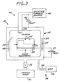
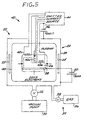
- Figures 3-8 illustrate embodiments of the invention consistent with the above description of the apparatus and method, which is incorporated.
- the single workpiece 26 is irregularly shaped.
- a single filament 42 and several shaped radiant heaters 25 are positioned to be closely adjacent to the heaviest section of the workpiece so as to preferentially heat the heaviest section of the workpiece.
- the result is a controllably uniform or nonuniform heat treatment. That is, in some cases it may be preferred to equally heat treat (and optionally surface treat) all of the regions of the irregularly shaped workpiece. In other cases, it may be preferred to preferentially heat treat (and optionally surface treat) regions of the workpiece.
- the judicious positioning of the filament and the heaters, and the processing parameters allows such selection of the processing.
- the single filament 42 is shaped to achieve a desired result.
- the filament 42 is shaped to conform to the surface of the workpiece.
- a first segment 42a of the filament is wound so as to achieve more emission than a second segment 42b.
- each workpiece 26 is placed into the chamber 22.
- the radiant wall heaters 25 are selected and powered such that, in combination with the heat produced by the filament 42, each workpiece 26 is heated uniformly regardless of its position relative to the other workpieces. If non-uniform heat treatment is desired, each workpiece may be individually biased, or the filament configuration can be changed.
- the plasma source 40 is positioned remotely from the chamber 22, but such that there is gaseous communication between the plasma source 40 and the interior of the chamber 22.
- the plasma is produced in the remote plasma source 40 and diffuses into the chamber 22. It is important that the plasma be non-uniform, and that the plasma have a potential near that of the chamber wall.
- the filament 42 is excited by a radio frequency (RF) transmitter 70 driven by a RF generator 72. That is, the thermionic power source is replaced by an RF power source.
- the filament 42 acts as an antenna.
- Figures 1 and 3-8 illustrate a number of features by which selectively uniform or nonuniform heat treatment and surface treatment can be accomplished.
- the various features can be used together in combinations other than those illustrated, and it is not the intent that the operable configurations be limited to those illustrated.
- multiple filaments could be used with multiple workpieces.
- the first chamber 22 was a cylinder about 2 feet in diameter and 3 feet long.
- the second chamber was a cylinder about 4 feet in diameter and 8 feet in length. Studies were performed to establish the operability of the present approach. The following examples are intended to illustrate the use of the invention, but should not be interpreted as limiting the scope or application of the invention in any respect.
- a single emission filament was heated using an AC emitter current source to provide a filament current of 20 amperes and filament voltage of 40 volts.
- a non-uniform plasma discharge was produced using a single filament that was small enough to produce a localized plasma that then filled the chamber nonuniformly.
- a DC filament bias voltage of 150 volts and 4 amperes.
- a DC workpiece bias voltage of about 150 volts and 100 milliamperes was applied for 30 minutes. During this time, the temperature of the part was maintained at about 400°C. No external heating from the chamber walls was used.
- the plates were studied microscopically after completion of the nitriding. It was found that nitrogen in solid solution had penetrated into the surfaces of the plates. Wear tests of the treated plates and untreated plates for comparison were conducted using a pin-on-disk wear tester. The wear tests verified a load-bearing capacity of the treated plates of about 1000 times the load-bearing capacity of the untreated plates.
- Gear blanks about 1-1/2 inches in diameter and 0.7 inches tall and made of 4118H pinion steel were processed in the first chamber.
- the chamber was evacuated to a background pressure of about 1,33 - 4,0 x 10 -4 Pa (1-3 x 10 -6 Torr) and backfilled with about 0,67 - 1,33 Pa (5-10 millitorr) of toluene (C 7 H 8 ) gas.
- the discharge voltage was 150 volts with a current of 10 amperes.
- a workpiece bias voltage of about 700-1000 volts was applied to the workpiece to heat the gear blanks, without the use of external chamber heaters, to about 900°C.
- a bias current of 400-550 milliamperes was observed.
- the gear blanks reached temperature about 5 minutes after the bias voltage was applied.
- the bias voltage was thereafter reduced to about 400 volts to maintain the 900°C temperature. After 30 minutes, processing was discontinued.
- the gear blank cooled to ambient temperature and was removed from the chamber.
- the gear blanks were uniformly carburized to a concentration of about 0.8-0.9 percent carbon to a depth of about 0.3-0.4 millimeters. This is the desired carburizing concentration and depth required for a commercial product.
- Gear blanks of the type used in Example 2 were placed into the first chamber onto the insulated support and allowed to electrically float, with no workpiece bias voltage being applied.
- the approach was otherwise similar to that of Example 2, except that 1-butene gas (C 4 H 8 ) was backfilled into the chamber to a pressure of about 1,33 Pa (10 millitorr).
- the filament was heated using an AC current of 60 amperes and a voltage of 160 volts.
- the discharge voltage was 150 volts, and a current of 40 amperes was obtained.
- the gear blanks reached an equilibrium temperature of about 730°C.
- the floating point potential of the gear blanks was 30-40 volts. This resulted in the deposition of a carbon layer at the surface of the gear blank which was used to later carburize the gear.
- the filaments were placed inside the second chamber.
- the filaments had lengths of four feet and were suspended in an equidistant manner across the length of the chamber.
- a two feet wide by four feet long workpiece support table was used.
- Several 304 stainless steel places as in Example 1 were placed on the support table.
- Uniform plasmas were produced by energizing all four filaments equally, resulting in uniform nitriding.
- Nonuniform plasmas were produced by energizing only a single filament, resulting in non-uniform nitriding.
Landscapes
- Chemical & Material Sciences (AREA)
- Engineering & Computer Science (AREA)
- Organic Chemistry (AREA)
- Chemical Kinetics & Catalysis (AREA)
- Materials Engineering (AREA)
- Mechanical Engineering (AREA)
- Metallurgy (AREA)
- Plasma & Fusion (AREA)
- Physics & Mathematics (AREA)
- General Chemical & Material Sciences (AREA)
- Analytical Chemistry (AREA)
- Health & Medical Sciences (AREA)
- Toxicology (AREA)
- Solid-Phase Diffusion Into Metallic Material Surfaces (AREA)
- Treatment Of Fiber Materials (AREA)
- Plasma Technology (AREA)
- Physical Or Chemical Processes And Apparatus (AREA)
Description
Claims (10)
- A plasma heating apparatus for heating a workpiece (26), comprising:a chamber (22) of sufficient size to receive the workpiece (26) therein and having a chamber wall (24);means (30-38) for producing a reduced gas pressure within the chamber (22) of from about 0,01 to about 100 millitorr (0,00133-13,3 Pa) during the heating of the workpiece,a plasma source (40) of an enveloping plasma (48),the plasma source (40) including an emitter of electrons other than the workpiece (26), wherein the potential of the emitter (42) is independent of the potential of the workpiece, characterized in thatthe chamber wall (24) is configured as an anode, and a radiant heater (25) is positioned within the chamber (22) to assist in the heating of the workpiece (26), the radiant heater (25) being operable independently of the plasma source (40).
- The apparatus of claim 1, characterized by a workpiece (26) located within the chamber (22).
- The apparatus of claim 2, characterized by a workpiece bias voltage source (50) connected between the workpiece (26) and the chamber wall (24).
- The apparatus of any of claims 1 - 3, characterized in that the means (30-38) for producing a reduced gas pressure includes a source (34) of a gas communicating with the interior of the chamber (22).
- The apparatus of claim 3, characterized in that the source (34) of a reactive gas is a source (34) of a non-reactive gas.
- The apparatus of any of claims 1 - 5, characterized in that the means (30-38) for producing a reduced pressure comprises:a vacuum pump (30) communicating with the interior of the vacuum chamber (22); anda source (34) of a gas controllably communicating with the interior of the chamber (22); and thatthe plasma source (40) of an enveloping plasma (48) comprises:a thermionic filament (42) located within the chamber (22);a current source (44) for the thermionic filament (42); anda filament bias voltage source (46) connected between the filament (42) and the chamber wall (24).
- The apparatus of claim 6, characterized in that the filament (42) comprises at least two filaments (42a-42e).
- A method for heating a workpiece (26), comprising: providing (60) an apparatus (20) including:a chamber (22) of sufficient size to receive the workpiece (26) therein and having a chamberwall (24); anda plasma source (40) of an enveloping plasma (48) located locally within the chamber (22), the chamber wall (24) being configured as an anode, the chamber further including an emitter of electrons other than the workpiece (26), wherein the potential of the emitter (42) is independent of the potential of the workpiece;.a radiant heater (25) within the chamber (22) positioned to assist in the heating of the workpiece (26)placing (62) the workpiece (26) within the chamber (22);producing (64) a gas pressure within the chamber (22) of from about 0.01 to about 100 millitorr (0,00133-13,3Pa) during the heating of the workpiece; andoperating (68) the plasma source (40) to heat the workpiece (26) and operating the radiant heater (25) independently of the plasma source (40).
- The method of claim 8, characterized by an additional step, performed during the step (68) of operating the plasma source, of varying the gas pressure to control charge exchange in the plasma (48).
- The method of claim 8 or 9, characterized by the further step (55) of negatively biasing the workpiece (26).
Applications Claiming Priority (3)
| Application Number | Priority Date | Filing Date | Title |
|---|---|---|---|
| US543860 | 1995-10-12 | ||
| US08/543,860 US5859404A (en) | 1995-10-12 | 1995-10-12 | Method and apparatus for plasma processing a workpiece in an enveloping plasma |
| PCT/US1996/016210 WO1997014172A1 (en) | 1995-10-12 | 1996-10-10 | Method and apparatus for plasma processing |
Publications (2)
| Publication Number | Publication Date |
|---|---|
| EP0797838A1 EP0797838A1 (en) | 1997-10-01 |
| EP0797838B1 true EP0797838B1 (en) | 2003-03-19 |
Family
ID=24169830
Family Applications (1)
| Application Number | Title | Priority Date | Filing Date |
|---|---|---|---|
| EP96934143A Expired - Lifetime EP0797838B1 (en) | 1995-10-12 | 1996-10-10 | Method and apparatus for plasma processing |
Country Status (6)
| Country | Link |
|---|---|
| US (1) | US5859404A (en) |
| EP (1) | EP0797838B1 (en) |
| JP (1) | JPH10503554A (en) |
| KR (1) | KR980700675A (en) |
| DE (1) | DE69626782T9 (en) |
| WO (1) | WO1997014172A1 (en) |
Cited By (1)
| Publication number | Priority date | Publication date | Assignee | Title |
|---|---|---|---|---|
| EP4046179A4 (en) * | 2019-10-16 | 2024-03-13 | US Electron, Inc. | Electron beam welding systems employing a plasma cathode |
Families Citing this family (36)
| Publication number | Priority date | Publication date | Assignee | Title |
|---|---|---|---|---|
| ES2210480T3 (en) * | 1997-04-18 | 2004-07-01 | Plasma Metal S.A. | PROCESS OF NITRURATION AND OVEN OF NITRURATION FOR ITS REALIZATION. |
| JP4643798B2 (en) * | 2000-05-31 | 2011-03-02 | パナソニック株式会社 | Surface treatment equipment |
| EP1288329A1 (en) * | 2001-09-03 | 2003-03-05 | C C R GmbH Beschichtungstechnologie | Process for fabricating of thin nitride- or oxide layers |
| US7049539B2 (en) * | 2002-04-01 | 2006-05-23 | Nagata Seiki Kabushiki Kaisha | Method for surface treating a die by electron beam irradiation and a die treated thereby |
| EP1361437A1 (en) * | 2002-05-07 | 2003-11-12 | Centre National De La Recherche Scientifique (Cnrs) | A novel biological cancer marker and methods for determining the cancerous or non-cancerous phenotype of cells |
| US7494904B2 (en) * | 2002-05-08 | 2009-02-24 | Btu International, Inc. | Plasma-assisted doping |
| US7465362B2 (en) * | 2002-05-08 | 2008-12-16 | Btu International, Inc. | Plasma-assisted nitrogen surface-treatment |
| US20060228497A1 (en) * | 2002-05-08 | 2006-10-12 | Satyendra Kumar | Plasma-assisted coating |
| US7504061B2 (en) * | 2002-05-08 | 2009-03-17 | Leonhard Kurz Gmbh & Co., Kg | Method of decorating large plastic 3D objects |
| US7445817B2 (en) * | 2002-05-08 | 2008-11-04 | Btu International Inc. | Plasma-assisted formation of carbon structures |
| US20050233091A1 (en) * | 2002-05-08 | 2005-10-20 | Devendra Kumar | Plasma-assisted coating |
| US20060057016A1 (en) * | 2002-05-08 | 2006-03-16 | Devendra Kumar | Plasma-assisted sintering |
| AU2003234476A1 (en) * | 2002-05-08 | 2003-11-11 | Dana Corporation | Plasma-assisted nitrogen surface-treatment |
| US7638727B2 (en) * | 2002-05-08 | 2009-12-29 | Btu International Inc. | Plasma-assisted heat treatment |
| US20060237398A1 (en) * | 2002-05-08 | 2006-10-26 | Dougherty Mike L Sr | Plasma-assisted processing in a manufacturing line |
| US20060062930A1 (en) * | 2002-05-08 | 2006-03-23 | Devendra Kumar | Plasma-assisted carburizing |
| US7432470B2 (en) | 2002-05-08 | 2008-10-07 | Btu International, Inc. | Surface cleaning and sterilization |
| US20060233682A1 (en) * | 2002-05-08 | 2006-10-19 | Cherian Kuruvilla A | Plasma-assisted engine exhaust treatment |
| US7497922B2 (en) * | 2002-05-08 | 2009-03-03 | Btu International, Inc. | Plasma-assisted gas production |
| US7560657B2 (en) * | 2002-05-08 | 2009-07-14 | Btu International Inc. | Plasma-assisted processing in a manufacturing line |
| US7498066B2 (en) * | 2002-05-08 | 2009-03-03 | Btu International Inc. | Plasma-assisted enhanced coating |
| US7189940B2 (en) | 2002-12-04 | 2007-03-13 | Btu International Inc. | Plasma-assisted melting |
| JP4257157B2 (en) * | 2003-06-13 | 2009-04-22 | 本田技研工業株式会社 | Nitriding processing method and apparatus |
| US7261914B2 (en) * | 2003-09-02 | 2007-08-28 | Southwest Research Institute | Method and apparatus for forming a nitride layer on a biomedical device |
| WO2006127037A2 (en) * | 2004-11-05 | 2006-11-30 | Dana Corporation | Atmospheric pressure processing using microwave-generated plasmas |
| US7687151B2 (en) * | 2005-04-12 | 2010-03-30 | General Electric Company | Overlay for repairing spline and seal teeth of a mated component |
| US7591057B2 (en) * | 2005-04-12 | 2009-09-22 | General Electric Company | Method of repairing spline and seal teeth of a mated component |
| US20070172689A1 (en) * | 2006-01-24 | 2007-07-26 | Standard Aero (San Antonio), Inc. | Treatment apparatus and method of treating surfaces |
| JP5606707B2 (en) * | 2009-09-04 | 2014-10-15 | 学校法人 名城大学 | Nitriding processing apparatus and nitriding processing method |
| ES2344981B1 (en) * | 2010-03-01 | 2011-05-06 | Asociacion De La Industria Navarra (Ain) | PROCEDURE FOR THE NITRURATION OF METAL ALLOYS AND DEVICE TO CARRY OUT THIS PROCEDURE. |
| KR101403989B1 (en) * | 2010-11-09 | 2014-06-10 | 포항공과대학교 산학협력단 | Graphene coated steel and method for preparing thereof |
| US8884525B2 (en) * | 2011-03-22 | 2014-11-11 | Advanced Energy Industries, Inc. | Remote plasma source generating a disc-shaped plasma |
| JP5956302B2 (en) * | 2012-10-15 | 2016-07-27 | 清水電設工業株式会社 | Plasma processing apparatus and method for forming hetero film |
| DE102013006589A1 (en) * | 2013-04-17 | 2014-10-23 | Ald Vacuum Technologies Gmbh | Method and device for the thermochemical hardening of workpieces |
| RU2611248C2 (en) * | 2015-06-25 | 2017-02-21 | Федеральное государственное бюджетное образовательное учреждение высшего профессионального образования "Уфимский государственный авиационный технический университет" | Method of nitriding parts in glow discharge at different depth of nitrated layer |
| CN115287583B (en) * | 2022-07-11 | 2024-01-30 | 华南理工大学 | Ion diffusion coating fixture device and method suitable for strengthening clock ring opening |
Citations (2)
| Publication number | Priority date | Publication date | Assignee | Title |
|---|---|---|---|---|
| US4600464A (en) * | 1985-05-01 | 1986-07-15 | International Business Machines Corporation | Plasma etching reactor with reduced plasma potential |
| DE19746332A1 (en) * | 1997-02-19 | 1998-08-27 | Fraunhofer Ges Forschung | Plasma=assisted chemical vapour deposition apparatus with reduced heating |
Family Cites Families (12)
| Publication number | Priority date | Publication date | Assignee | Title |
|---|---|---|---|---|
| CH611938A5 (en) * | 1976-05-19 | 1979-06-29 | Battelle Memorial Institute | |
| JPS581186B2 (en) * | 1977-12-13 | 1983-01-10 | 双葉電子工業株式会社 | Ion plating device |
| US4394234A (en) * | 1979-02-02 | 1983-07-19 | Hitachi, Ltd. | Method of processing electrically conductive material by glow discharge |
| US4342631A (en) * | 1980-06-16 | 1982-08-03 | Illinois Tool Works Inc. | Gasless ion plating process and apparatus |
| US4764394A (en) * | 1987-01-20 | 1988-08-16 | Wisconsin Alumni Research Foundation | Method and apparatus for plasma source ion implantation |
| JP2572438B2 (en) * | 1989-01-30 | 1997-01-16 | ホーヤ株式会社 | Manufacturing method of glass press mold |
| US5078847A (en) * | 1990-08-29 | 1992-01-07 | Jerry Grosman | Ion plating method and apparatus |
| GB2251631B (en) * | 1990-12-19 | 1994-10-12 | Mitsubishi Electric Corp | Thin-film forming apparatus |
| GB2261227B (en) * | 1991-11-08 | 1995-01-11 | Univ Hull | Surface treatment of metals |
| US5374456A (en) * | 1992-12-23 | 1994-12-20 | Hughes Aircraft Company | Surface potential control in plasma processing of materials |
| US5498290A (en) * | 1993-08-27 | 1996-03-12 | Hughes Aircraft Company | Confinement of secondary electrons in plasma ion processing |
| US5571332A (en) * | 1995-02-10 | 1996-11-05 | Jet Process Corporation | Electron jet vapor deposition system |
-
1995
- 1995-10-12 US US08/543,860 patent/US5859404A/en not_active Expired - Lifetime
-
1996
- 1996-10-10 JP JP9515182A patent/JPH10503554A/en not_active Ceased
- 1996-10-10 DE DE69626782T patent/DE69626782T9/en active Active
- 1996-10-10 WO PCT/US1996/016210 patent/WO1997014172A1/en not_active Ceased
- 1996-10-10 EP EP96934143A patent/EP0797838B1/en not_active Expired - Lifetime
- 1996-10-10 KR KR1019970703915A patent/KR980700675A/en not_active Ceased
Patent Citations (2)
| Publication number | Priority date | Publication date | Assignee | Title |
|---|---|---|---|---|
| US4600464A (en) * | 1985-05-01 | 1986-07-15 | International Business Machines Corporation | Plasma etching reactor with reduced plasma potential |
| DE19746332A1 (en) * | 1997-02-19 | 1998-08-27 | Fraunhofer Ges Forschung | Plasma=assisted chemical vapour deposition apparatus with reduced heating |
Cited By (1)
| Publication number | Priority date | Publication date | Assignee | Title |
|---|---|---|---|---|
| EP4046179A4 (en) * | 2019-10-16 | 2024-03-13 | US Electron, Inc. | Electron beam welding systems employing a plasma cathode |
Also Published As
| Publication number | Publication date |
|---|---|
| KR980700675A (en) | 1998-03-30 |
| DE69626782D1 (en) | 2003-04-24 |
| MX9704311A (en) | 1998-06-28 |
| JPH10503554A (en) | 1998-03-31 |
| EP0797838A1 (en) | 1997-10-01 |
| WO1997014172A1 (en) | 1997-04-17 |
| DE69626782T2 (en) | 2004-02-12 |
| US5859404A (en) | 1999-01-12 |
| DE69626782T9 (en) | 2004-07-22 |
Similar Documents
| Publication | Publication Date | Title |
|---|---|---|
| US5859404A (en) | Method and apparatus for plasma processing a workpiece in an enveloping plasma | |
| US5712000A (en) | Large-scale, low pressure plasma-ion deposition of diamondlike carbon films | |
| US4500564A (en) | Method for surface treatment by ion bombardment | |
| US4764394A (en) | Method and apparatus for plasma source ion implantation | |
| Collins et al. | Ion-assisted surface modification by plasma immersion ion implantation | |
| US5278861A (en) | Method of treating metals by deposition of materials and furnace for implementing said method | |
| Koval et al. | Generation of low-temperature gas discharge plasma in large vacuum volumes for plasma chemical processes | |
| US20050061251A1 (en) | Apparatus and method for metal plasma immersion ion implantation and metal plasma immersion ion deposition | |
| US9139902B2 (en) | Method and apparatus for plasma ion implantation of solid element | |
| Paosawatyanyong et al. | Nitriding of tool steel using dual DC/RFICP plasma process | |
| US4555611A (en) | Method and apparatus for uniformly heating articles in a vacuum container | |
| JP2004292934A (en) | Ion nitriding apparatus and deposition system using the same | |
| CA2207273C (en) | Method and apparatus for plasma processing | |
| KR20150110968A (en) | Method and system for nitriding bore of pipe with hollow cathode discharge | |
| JP2002194527A (en) | Nitriding equipment using electron beam excited plasma | |
| KR20100083545A (en) | Method and apparatus for ion implantation of non-gaseous elements | |
| US7074460B2 (en) | Method for treating the surface of a part and resulting part | |
| KR100317731B1 (en) | High density plasma ion nitriding method and apparatus | |
| MXPA97004311A (en) | Method and apparatus for the processing of pla | |
| JP4859523B2 (en) | Plasma source, film forming apparatus and film manufacturing method | |
| JPH01302645A (en) | Discharging device | |
| JPH08260126A (en) | Method for surface melt hardening of aluminum substrate | |
| JPH06280000A (en) | Plasma surface treatment method and device | |
| RU2312932C2 (en) | Device for vacuum plasma treatment of articles | |
| CN114164395A (en) | Ionic nitrogen carbon sulfur multi-element co-cementation equipment, processing system and method |
Legal Events
| Date | Code | Title | Description |
|---|---|---|---|
| PUAI | Public reference made under article 153(3) epc to a published international application that has entered the european phase |
Free format text: ORIGINAL CODE: 0009012 |
|
| AK | Designated contracting states |
Kind code of ref document: A1 Designated state(s): DE FR GB IT SE |
|
| 17P | Request for examination filed |
Effective date: 19970923 |
|
| RAP1 | Party data changed (applicant data changed or rights of an application transferred) |
Owner name: GENERAL MOTORS CORPORATION Owner name: HUGHES ELECTRONICS CORPORATION |
|
| 17Q | First examination report despatched |
Effective date: 19990708 |
|
| GRAH | Despatch of communication of intention to grant a patent |
Free format text: ORIGINAL CODE: EPIDOS IGRA |
|
| GRAH | Despatch of communication of intention to grant a patent |
Free format text: ORIGINAL CODE: EPIDOS IGRA |
|
| GRAA | (expected) grant |
Free format text: ORIGINAL CODE: 0009210 |
|
| AK | Designated contracting states |
Designated state(s): DE FR GB IT SE |
|
| PG25 | Lapsed in a contracting state [announced via postgrant information from national office to epo] |
Ref country code: IT Free format text: LAPSE BECAUSE OF FAILURE TO SUBMIT A TRANSLATION OF THE DESCRIPTION OR TO PAY THE FEE WITHIN THE PRESCRIBED TIME-LIMIT;WARNING: LAPSES OF ITALIAN PATENTS WITH EFFECTIVE DATE BEFORE 2007 MAY HAVE OCCURRED AT ANY TIME BEFORE 2007. THE CORRECT EFFECTIVE DATE MAY BE DIFFERENT FROM THE ONE RECORDED. Effective date: 20030319 |
|
| REG | Reference to a national code |
Ref country code: GB Ref legal event code: FG4D |
|
| REF | Corresponds to: |
Ref document number: 69626782 Country of ref document: DE Date of ref document: 20030424 Kind code of ref document: P |
|
| PG25 | Lapsed in a contracting state [announced via postgrant information from national office to epo] |
Ref country code: SE Free format text: LAPSE BECAUSE OF FAILURE TO SUBMIT A TRANSLATION OF THE DESCRIPTION OR TO PAY THE FEE WITHIN THE PRESCRIBED TIME-LIMIT Effective date: 20030619 |
|
| ET | Fr: translation filed | ||
| PLBE | No opposition filed within time limit |
Free format text: ORIGINAL CODE: 0009261 |
|
| STAA | Information on the status of an ep patent application or granted ep patent |
Free format text: STATUS: NO OPPOSITION FILED WITHIN TIME LIMIT |
|
| 26N | No opposition filed |
Effective date: 20031222 |
|
| REG | Reference to a national code |
Ref country code: FR Ref legal event code: PLFP Year of fee payment: 20 |
|
| PGFP | Annual fee paid to national office [announced via postgrant information from national office to epo] |
Ref country code: GB Payment date: 20151021 Year of fee payment: 20 Ref country code: DE Payment date: 20151022 Year of fee payment: 20 |
|
| PGFP | Annual fee paid to national office [announced via postgrant information from national office to epo] |
Ref country code: FR Payment date: 20151023 Year of fee payment: 20 |
|
| REG | Reference to a national code |
Ref country code: DE Ref legal event code: R071 Ref document number: 69626782 Country of ref document: DE |
|
| REG | Reference to a national code |
Ref country code: GB Ref legal event code: PE20 Expiry date: 20161009 |
|
| PG25 | Lapsed in a contracting state [announced via postgrant information from national office to epo] |
Ref country code: GB Free format text: LAPSE BECAUSE OF EXPIRATION OF PROTECTION Effective date: 20161009 |