EP0797069B1 - Vorrichtung zur Abtastung eines Gesichtsfeldes - Google Patents
Vorrichtung zur Abtastung eines Gesichtsfeldes Download PDFInfo
- Publication number
- EP0797069B1 EP0797069B1 EP97103934A EP97103934A EP0797069B1 EP 0797069 B1 EP0797069 B1 EP 0797069B1 EP 97103934 A EP97103934 A EP 97103934A EP 97103934 A EP97103934 A EP 97103934A EP 0797069 B1 EP0797069 B1 EP 0797069B1
- Authority
- EP
- European Patent Office
- Prior art keywords
- scanning
- sensors
- imaging beam
- laser
- beam paths
- Prior art date
- Legal status (The legal status is an assumption and is not a legal conclusion. Google has not performed a legal analysis and makes no representation as to the accuracy of the status listed.)
- Expired - Lifetime
Links
- 230000000007 visual effect Effects 0.000 title description 4
- 238000003384 imaging method Methods 0.000 claims description 25
- 230000003287 optical effect Effects 0.000 claims description 20
- 230000005855 radiation Effects 0.000 claims description 9
- 230000005670 electromagnetic radiation Effects 0.000 claims description 4
- 230000000737 periodic effect Effects 0.000 claims description 4
- 230000003595 spectral effect Effects 0.000 claims description 4
- 238000005070 sampling Methods 0.000 description 5
- 238000012634 optical imaging Methods 0.000 description 4
- 230000005540 biological transmission Effects 0.000 description 1
- 238000005422 blasting Methods 0.000 description 1
- 238000010276 construction Methods 0.000 description 1
- 230000001419 dependent effect Effects 0.000 description 1
- 238000005286 illumination Methods 0.000 description 1
- 238000009434 installation Methods 0.000 description 1
- 238000005259 measurement Methods 0.000 description 1
- 238000000034 method Methods 0.000 description 1
- 238000011144 upstream manufacturing Methods 0.000 description 1
Images

Classifications
-
- F—MECHANICAL ENGINEERING; LIGHTING; HEATING; WEAPONS; BLASTING
- F41—WEAPONS
- F41G—WEAPON SIGHTS; AIMING
- F41G7/00—Direction control systems for self-propelled missiles
- F41G7/34—Direction control systems for self-propelled missiles based on predetermined target position data
- F41G7/343—Direction control systems for self-propelled missiles based on predetermined target position data comparing observed and stored data of target position or of distinctive marks along the path towards the target
Definitions
- the invention relates to a device for scanning a visual field by means of a Plurality of electromagnetic radiation responsive sensors with imaging optical means through which overlapping areas of the visual field in imaging beam paths on the different sensors and a common optical deflection system (22; 40) for periodic imaging Distraction of all imaging beam paths
- US-PS-5 332 176 describes an apparatus for detecting an object. To for this purpose, a detector assembly is reciprocated by a motor, that a certain field of view is detected. In this way, the position of the Object detected.
- U.S. Patent No. 3,822,098 discloses an apparatus for detecting and identifying Objects.
- a laser beam is detected by means of a scanning mirror on an object to be detected directed and reflected from the object radiation is from a Multispectral sensor detected.
- the multispectral sensor consists of an optical system and a plurality of detectors disposed behind the optical system.
- the optical System contains lenses and a Nicols prism.
- the detectors are filters upstream, whereby the detectors respond to light of different frequencies.
- an optical scanning system for use in a Laser printer known.
- the light of a laser passes through an optical system and is noticeable a polygon mirror which reflects the laser beam onto a scanning surface.
- the scanning is scanned line by line.
- the Scanning surface is at a predetermined speed perpendicular to the Scanning movement of the laser beam moves.
- an electric supplied to the laser Signal the shape and size of the laser beam spot can be changed.
- DE-C-3 615 374 a device for pivotable blasting of Laser energy known.
- a laser beam from a fixed laser is transmitted through a rotating deflecting mirror emitted in different directions.
- the deflection mirror is adjusted by several servomotors.
- the servomotors and the deflection mirror are stored in a radiation-permeable material existing hollow body, so that the laser beam can be directed in any direction. This will be constructive conditional shadowing of the laser beam in individual directions avoided.
- image drones are often with one on infrared Radiation responsive, image-resolving sensor and an image processing system provided to recognize targets even at night or poor visibility can.
- the invention has for its object to provide a device which the Scanning of a terrain, by various independent Image beam paths with clear spatial allocation by each Imaging beam path detected areas of the field of view or terrain allowed.
- Imaging beam paths are by a common deflection in the same Way distracted. This ensures that the different An imaging beam paths associated areas of the visual field or terrain have defined position to each other, usually coincide substantially. It can then be sensitive by different, in different spectral ranges Sensors are observed one and the same point of the terrain. From the Information supplied by the various sensors can provide conclusions be drawn to the nature of an object located at this point. It is also possible, in an imaging beam path to a terrain by means of a laser illuminate, with the laser only one light spot stroking the terrain generated. The light spot illuminated in each case becomes in another Imaging beam path by a responsive to the wavelength of the laser Sensor observed.
- the common deflection system ensures a clear Assignment of the observed points to each other and also ensures that the sensor always accurately observed the light spot generated by the laser.
- the transmission power of the Lasers can be kept low.
- Embodiments of the invention are the subject of the dependent claims.
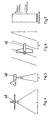
- Fig.1 and 2 is an embodiment of a scanning device, for use in a Pictured drone.
- the first sensor is designated 10.
- the first Sensor 10 is associated with a first optical imaging system 12.
- Transverse to the direction of flight seen is next to the first sensor 10 responsive to visible light, second Sensor 14 is arranged.
- the second sensor 14 is a second optical imaging System 16 assigned. Both the working in the infrared region sensor 10 and the in the visible range working sensor 14 are shown in the Embodiments designed as line detectors, wherein the sensor 14 is an RGB line detector (Red-green-blue) can be.
- RGB line detector Red-green-blue
- a laser 18 is arranged as a light source.
- the laser 18 a third optical system 20 is assigned.
- the Laser 18, a laser diode array and the laser associated with the optical system 20th contains a cylindrical lens for widening the beam path.
- a polygon mirror is designated 22.
- the polygon mirror 22 is one Longitudinal axis 24 rotatably and mounted on a shaft 26.
- the polygon mirror 22 has 12 pages, one of which is labeled 28.
- the number of pages of the However, polygon mirror can be arbitrary, generally N. In the illustrated Embodiment illustrate the pages 28 plane mirror surfaces.
- Fig.1 are the sensors 10 and 14 and the laser 18 and the optical imaging Systems 12, 16 and 20 in a row, so that they partially hidden in the illustration are.
- the optically imaging systems 12, 16 of the sensors 10 and 14 are shown in FIG a convex lens 30, a concave lens 32, a fixed deflecting mirror 34 and a convex lens 36 shown representatively, wherein the deflection mirror 34 for Reduction of the overall length is used.
- a pivotable about an axis 42 deflecting mirror is designated 44.
- the Extension of the polygon mirror 22, the scanning mirror 40 and the deflection mirror 44th in the direction of the longitudinal axis 24 or in the direction transverse to the direction of flight is chosen such that that the radiation assigned to the intended sensors and the intended lasers is detected.
- the sensors 10 and 14 are responsive to electromagnetic radiation emitted by the under the drone located terrain comes.
- the ray path of this Electromagnetic radiation is shown in FIGS. 1 and 3 by arrows.
- the radiation initially falls on the pivotable deflection mirror 44.
- the deflection mirror 44 directs the Radiation on the polygon mirror 22 ( Figure 1) or on the pivotable mirror 40th (Fig.3). From there, the radiation passes through the optically imaging systems 12 and 16 to the sensors 10 and 14.
- the laser light emitted by the laser 18 initially extends in the direction of the corner through the optical imaging system 20 then hits the polygon mirror 22 (FIG. or on the Abtastapt 40 ( Figure 3) and is about the deflection mirror 44 to the terrain directed.
- the laser light serves to illuminate the terrain. This is it necessary that the illuminated area and the fields of view of the sensors 10 and 14th overlap at least partially and are ideally identical.
- the image excerpts The individual sensors 10 and 14 and the laser 18 initially differ by the spatial distance of the sensors 10 and 14 and the laser 18. This spatial Distances and possible installation and adjustment errors remain after the construction of such Scanning device, however, constant, and therefore can be corrected.
- the working in the visible range sensor 14 also be used at night, taking in at least one of the three RGB channels is illuminated.
- the illumination in the red channel above ⁇ 780 nm, since the laser light in this spectral range is not visible to the naked eye is visible.
- the sampling of the Terrain by rotation of the polygon mirror 22 The size of the scanning angle across the Direction of flight depends on the number of sides 28 of the polygonal ball 22. With For a polygon mirror with N sides, the scan angle is 720 / N. The scan always takes place in one direction only ("forward scan"). If indeed one Area (e.g., 28) of the polygon mirror 22 in the field of view of the sensors 10 and 14 or enters the beam path of the laser 18, the scanning process starts again from a Starting position on.
- Area e.g., 28
- the sampling of the terrain takes place by pivoting the scanning mirror 40 in the by a double arrow 46th indicated directions.
- the size of the scanning angle depends on the direction of flight It depends on the swing amplitude of the scanning mirror 40 and is finally by the Size of the scanning mirror 40 limited. Because the deflecting mirror 40 pivots back and forth Weden, it is possible in this embodiment, the sampling in two Directions ("forward and backward scanning").
- the deflection mirror 44 By pivoting the deflecting mirror 44 about the axis 42, the field of view of the Scanning device can be changed as desired.
- the deflection mirror 44 thus serves not scanning the terrain, but sets the area that scanned shall be.
- the deflection mirror 44 can also be equipped with a controller (not shown) be provided, through which the deflection mirror 44 is pivoted to changes the rollage of the drone (or any other manned or unmanned Aircraft).
- the scanning takes place exclusively transversely to Flight direction.
- the scanning of the terrain in the direction of flight is performed by the Forward movement of the image drone itself. This is shown in Figures 4 to 6.
- the image drone 48 is a scanning device of the type described.
- Fig.4 the picture drone is shown once in the direction of flight.
- 5 shows the image drone across the Flight direction.
- the scanning angle ⁇ transverse to the direction depends, as explained above, from the conditions of the polygon mirror 22 (FIG. 1) or of the scanning mirror 40 (FIG. 3). At a certain altitude then you get a certain scan length B across to Flight direction.
- the scanning angle ⁇ in the direction of flight depends on the size of the Field of view of the sensors 10 and 14 and the expansion of the beam of the laser 18th from. At a certain altitude, one then obtains a certain scanning depth A in Flight direction.
- FIG. 6 shows the image drone 48 from above.
- the Scanning speed must be changed by the joint deflection of the the radiation associated with the sensors and the laser ensures that this change for all sensors and lasers in the same way.
- the scanning device is described here in connection with a picture drone. It should be noted, however, that the principle of such a sampling system is not limited to Drones or other aircraft is used, but in all other Devices with which a scan is made.
- the scanner has more than two sensors and more than can contain a laser. Depending on your requirements, sensors for a wide variety of Spectral ranges are used. It can also, for example, multiple lasers be provided, which emits light of different wavelengths. It continues possible to integrate radar systems in the same way.
Landscapes
- Engineering & Computer Science (AREA)
- Chemical & Material Sciences (AREA)
- Combustion & Propulsion (AREA)
- General Engineering & Computer Science (AREA)
- Optical Radar Systems And Details Thereof (AREA)
- Length Measuring Devices By Optical Means (AREA)
- Control Of Position, Course, Altitude, Or Attitude Of Moving Bodies (AREA)
Description
- Fig.1
- ist eine schematische Darstellung und zeigt ein ersten Ausführungsbeispiels einer in eine Bilddrohne eingebauten Vorrichtung zum Abtasten eines Gesichtsfeldes durch mehrere Abbildungsstrahlengänge, und zwar in Flugrichtung der Bilddrohne gesehen.
- Fig.2
- zeigt die erfindungswesentlichen Teile der Vorrichtung von Fig.1 quer zur Flugrichtung gesehen.
- Fig.3
- ist eine schematische Darstellung ähnlich Fig.1 und zeigt die erfindungswesentlichen Teile eines zweiten Ausführungsbeispiels einer solchen Abtastvorrichtung.
- Fig.4
- ist eine schematische Darstellung und zeigt eine in Flugrichtung der Bilddrohne gesehen die Möglichkeit des Abtastens eines Geländes mittels einer in die Bilddrohne eingebauten Abtastvorrichtung.
- Fig.5
- zeigt schematisch die Abtastung des Geländes durch die Abtastvorrichtung quer zur Flugrichtung der Bilddrohne gesehen.
- Fig.6
- ist eine Draufsicht auf die Bilddrohne und veranschaulicht die Lage der durch die Abtastvorrichtung abgetasteten Geländestreifen.
- Fig.7
- veranschaulicht die Abtastung eines Geländestreifens mittels eines als Zeilendetektor ausgebildeten Sensors.
Claims (11)
- Vorrichtung zur Abtastung eines Gesichtsfeldes mittels einer Mehrzahl von auf elektromagnetische Strahlung ansprechender Sensoren mit abbildenden optischen Mitteln, durch welche überlappende Bereiche des Gesichtsfeldes in Abbildungsstrahlengängen auf den verschiedenen Sensoren abbildbar sind, und ein gemeinsames optisches Ablenksystem (22; 40) zur periodischen Ablenkung aller Abbildungsstrahlengänge
dadurch gekennzeichnet daß(a) die abbildenden optischen Mittel für jeden der Sensoren ein eigenes optisches System (12,16,20) mit einem getrennten Abbildungsstrahlengang aufweisen und(b) zur Erzeugung einer Abtastbewegung die Abbildungsstrahlengänge nebeneinander über ein gemeinsames optisches Ablenksystem (22;40) zur periodischen Ablenkung aller Abbildungsstrahlengänge geführt sind. - Vorrichtung nach Anspruch 1, dadurch gekennzeichnet, daß die Sensoren (10,14) in unterschiedlichen Spektralbereichen empfindlich sind.
- Vorrichtung nach Anspruch 2, dadurch gekennzeichnet, daß(a) in wenigstens einem der Abbildungsstrahlengänge ein Bereich des abzutastenden Gesichtsfeldes mittels einer vorrichtungsseitigen Lichtquelle (18) beleuchtbar ist und(b) in einem anderen Abbildungsstrahlengang durch das optische System (16) wenigstens ein Teil des so beleuchteten Bereiches auf einen für die Strahlung der Lichtquelle (18) empfindlichen Sensor (14) abbildbar ist.
- Vorrichtung nach einem der Ansprüche 1 bis 3, dadurch gekennzeichnet, daß das Ablenksystem einen schwenkbaren Abtastspiegel (40) enthält.
- Vorrichtung nach einem der Ansprüche 1 bis 3, dadurch gekennzeichnet, daß das Ablenksystem einen rotierenden Polygonspiegel (22) enthält.
- Vorrichtung nach einem der Ansprüche 1 bis 5, dadurch gekennzeichnet, daß mindestens ein der Sensoren (10) auf infrarote Strahlung anspricht.
- Vorrichtung nach einem der Ansprüche 1 bis 6, dadurch gekennzeichnet, daß mindestens ein der Sensoren (14) auf sichtbares Licht anspricht.
- Vorrichtung nach Anspruch 3, dadurch gekennzeichnet, daß(a) die Lichtquelle ein Laser (18) ist und(b) der Sensor (10 bzw. 14) auf Licht des Wellenlängenbereichs des Laserslichts anspricht.
- Vorrichtung nach Anspruch 8, dadurch gekennzeichnet, daß der Laser (18) infrarotes Licht aussendet.
- Vorrichtung nach einem der Ansprüche 1 bis 9, gekennzeichnet durch einen Umlenkspiegel (44) zur Beeinflussung des durch das Ablenksystem (22;40) abzutastenden Bereichs.
- Vorrichtung nach einem der Ansprüche 1 bis 10, dadurch gekennzeichnet, daß(a) die Vorrichtung in einem Luftfahrzeug (48) angeordnet ist und(b) das Ablenksystem (22;40) die Abbildungsstrahlengänge nur in Richtungen senkrecht zur Flugrichtung des Luftfahrzeugs (48) ablenkt.
Applications Claiming Priority (2)
| Application Number | Priority Date | Filing Date | Title |
|---|---|---|---|
| DE19611609 | 1996-03-23 | ||
| DE19611609A DE19611609A1 (de) | 1996-03-23 | 1996-03-23 | Vorrichtung zur Abtastung eines Gesichtsfeldes |
Publications (3)
| Publication Number | Publication Date |
|---|---|
| EP0797069A2 EP0797069A2 (de) | 1997-09-24 |
| EP0797069A3 EP0797069A3 (de) | 1999-12-29 |
| EP0797069B1 true EP0797069B1 (de) | 2005-06-08 |
Family
ID=7789258
Family Applications (1)
| Application Number | Title | Priority Date | Filing Date |
|---|---|---|---|
| EP97103934A Expired - Lifetime EP0797069B1 (de) | 1996-03-23 | 1997-03-10 | Vorrichtung zur Abtastung eines Gesichtsfeldes |
Country Status (2)
| Country | Link |
|---|---|
| EP (1) | EP0797069B1 (de) |
| DE (2) | DE19611609A1 (de) |
Families Citing this family (2)
| Publication number | Priority date | Publication date | Assignee | Title |
|---|---|---|---|---|
| CN104020474B (zh) * | 2014-05-06 | 2016-08-24 | 南京大学 | 一种激光三维成像光学收发系统 |
| DE102015105560A1 (de) * | 2015-04-13 | 2016-10-13 | Hamburg Innovation Gmbh | Sensorvorrichtung mit optoelektronischem Sensor und Messbereichserweiterung |
Family Cites Families (3)
| Publication number | Priority date | Publication date | Assignee | Title |
|---|---|---|---|---|
| US3822098A (en) * | 1973-05-02 | 1974-07-02 | Mc Donnell Douglas Corp | Multispectral sensor means measuring depolarized radiation |
| FR2536851B1 (fr) * | 1982-11-30 | 1985-06-14 | Aerospatiale | Systeme de reconnaissance comportant un vehicule aerien tournant autour de son axe longitudinal |
| DE3570529D1 (en) * | 1984-03-05 | 1989-06-29 | Siemens Ag | Optical system for the simultaneous reception of thermal and laser radiation |
-
1996
- 1996-03-23 DE DE19611609A patent/DE19611609A1/de not_active Withdrawn
-
1997
- 1997-03-10 DE DE59712336T patent/DE59712336D1/de not_active Expired - Fee Related
- 1997-03-10 EP EP97103934A patent/EP0797069B1/de not_active Expired - Lifetime
Non-Patent Citations (1)
| Title |
|---|
| WALKER; GORDON: "Astronomical Observations", 1987, CAMBRIDGE UNIVERSITY PRESS, CAMBRIDGE, NY, USA * |
Also Published As
| Publication number | Publication date |
|---|---|
| DE19611609A1 (de) | 1997-09-25 |
| EP0797069A2 (de) | 1997-09-24 |
| EP0797069A3 (de) | 1999-12-29 |
| DE59712336D1 (de) | 2005-07-14 |
Similar Documents
| Publication | Publication Date | Title |
|---|---|---|
| EP3350615B1 (de) | Lidarsensor | |
| EP0578129B1 (de) | Bilderfassende Sensoreinheit | |
| EP2533003B1 (de) | Optische Vorrichtung zum Führen von Strahlung einer Objektszene auf einen Detektor | |
| EP1022600B1 (de) | Stabilisierte Kamera | |
| EP2202533A1 (de) | Erfassungsvorrichtung | |
| DE3876233T2 (de) | Optischer scanner mit hohem wirkungsgrad. | |
| EP3832344B1 (de) | Optoelektronischer sensor und verfahren zur erfassung eines objekts | |
| CH700023B1 (de) | Scan-Einrichtung. | |
| DE102019125684B4 (de) | Optoelektronischer Sensor und Verfahren zur Erfassung von Objekten | |
| EP2433837A1 (de) | Optisches Instrument und Verfahren zur optischen Überwachung der Umgebung sich langsam bewegender Fahrzeuge | |
| DE68920544T2 (de) | Detektor-Matrix-Anordnung für Infrarot-Zeilenabtaster grosser Geschwindigkeit/Höhe Verhältnissen. | |
| DE69727060T2 (de) | Beobachtungs- und zielsystem | |
| EP2761343B1 (de) | Nachführvorrichtung für einen lichtstrahl | |
| DE102021111949B4 (de) | Vorrichtung zur scannenden Messung des Abstands zu einem Objekt | |
| EP1248120B1 (de) | Dual-Mode Suchkopf | |
| DE102020102247A1 (de) | Optoelektronischer Sensor und Verfahren zur Erfassung von Objekten | |
| DE3614159C2 (de) | ||
| DE2800473C2 (de) | Optische Abtasteinrichtung | |
| DE69304278T2 (de) | Abtaster für kleine Winkel | |
| EP3736603B1 (de) | Optoelektronischer sensor und verfahren zur überwachung eines überwachungsbereichs | |
| DE102018113849B4 (de) | Optoelektronischer Sensor und Verfahren zu Erfassung von Objekten | |
| DE202011052106U1 (de) | Entfernungsmessender optoelektronischer Sensor | |
| EP0797069A2 (de) | Vorrichtung zur Abtastung eines Gesichtsfeldes | |
| DE3330495C2 (de) | Einrichtung zur Lenkung eines Flugkörpers in ein Ziel | |
| EP0533036B1 (de) | Suchkopf |
Legal Events
| Date | Code | Title | Description |
|---|---|---|---|
| PUAI | Public reference made under article 153(3) epc to a published international application that has entered the european phase |
Free format text: ORIGINAL CODE: 0009012 |
|
| AK | Designated contracting states |
Kind code of ref document: A2 Designated state(s): DE FR GB SE |
|
| PUAL | Search report despatched |
Free format text: ORIGINAL CODE: 0009013 |
|
| AK | Designated contracting states |
Kind code of ref document: A3 Designated state(s): DE FR GB SE |
|
| 17P | Request for examination filed |
Effective date: 19991125 |
|
| 17Q | First examination report despatched |
Effective date: 20020507 |
|
| GRAP | Despatch of communication of intention to grant a patent |
Free format text: ORIGINAL CODE: EPIDOSNIGR1 |
|
| GRAS | Grant fee paid |
Free format text: ORIGINAL CODE: EPIDOSNIGR3 |
|
| RAP1 | Party data changed (applicant data changed or rights of an application transferred) |
Owner name: DIEHL BGT DEFENCE GMBH & CO.KG |
|
| GRAA | (expected) grant |
Free format text: ORIGINAL CODE: 0009210 |
|
| AK | Designated contracting states |
Kind code of ref document: B1 Designated state(s): DE FR GB SE |
|
| REG | Reference to a national code |
Ref country code: GB Ref legal event code: FG4D Free format text: NOT ENGLISH |
|
| REF | Corresponds to: |
Ref document number: 59712336 Country of ref document: DE Date of ref document: 20050714 Kind code of ref document: P |
|
| REG | Reference to a national code |
Ref country code: SE Ref legal event code: TRGR |
|
| GBT | Gb: translation of ep patent filed (gb section 77(6)(a)/1977) |
Effective date: 20050919 |
|
| PG25 | Lapsed in a contracting state [announced via postgrant information from national office to epo] |
Ref country code: GB Free format text: LAPSE BECAUSE OF NON-PAYMENT OF DUE FEES Effective date: 20060310 |
|
| PG25 | Lapsed in a contracting state [announced via postgrant information from national office to epo] |
Ref country code: SE Free format text: LAPSE BECAUSE OF NON-PAYMENT OF DUE FEES Effective date: 20060311 |
|
| ET | Fr: translation filed | ||
| PLBE | No opposition filed within time limit |
Free format text: ORIGINAL CODE: 0009261 |
|
| STAA | Information on the status of an ep patent application or granted ep patent |
Free format text: STATUS: NO OPPOSITION FILED WITHIN TIME LIMIT |
|
| PGFP | Annual fee paid to national office [announced via postgrant information from national office to epo] |
Ref country code: DE Payment date: 20060516 Year of fee payment: 10 |
|
| 26N | No opposition filed |
Effective date: 20060309 |
|
| EUG | Se: european patent has lapsed | ||
| GBPC | Gb: european patent ceased through non-payment of renewal fee |
Effective date: 20060310 |
|
| REG | Reference to a national code |
Ref country code: FR Ref legal event code: ST Effective date: 20061130 |
|
| PG25 | Lapsed in a contracting state [announced via postgrant information from national office to epo] |
Ref country code: FR Free format text: LAPSE BECAUSE OF NON-PAYMENT OF DUE FEES Effective date: 20060331 Ref country code: DE Free format text: LAPSE BECAUSE OF NON-PAYMENT OF DUE FEES Effective date: 20071002 |