EP0797061A2 - Luftkochendes kryogenisches Rektifikationssystem mit stufenweiser Luftkondensation - Google Patents
Luftkochendes kryogenisches Rektifikationssystem mit stufenweiser Luftkondensation Download PDFInfo
- Publication number
- EP0797061A2 EP0797061A2 EP97101484A EP97101484A EP0797061A2 EP 0797061 A2 EP0797061 A2 EP 0797061A2 EP 97101484 A EP97101484 A EP 97101484A EP 97101484 A EP97101484 A EP 97101484A EP 0797061 A2 EP0797061 A2 EP 0797061A2
- Authority
- EP
- European Patent Office
- Prior art keywords
- column
- air
- vapor
- liquid
- pressure column
- Prior art date
- Legal status (The legal status is an assumption and is not a legal conclusion. Google has not performed a legal analysis and makes no representation as to the accuracy of the status listed.)
- Withdrawn
Links
Images
Classifications
-
- F—MECHANICAL ENGINEERING; LIGHTING; HEATING; WEAPONS; BLASTING
- F25—REFRIGERATION OR COOLING; COMBINED HEATING AND REFRIGERATION SYSTEMS; HEAT PUMP SYSTEMS; MANUFACTURE OR STORAGE OF ICE; LIQUEFACTION SOLIDIFICATION OF GASES
- F25J—LIQUEFACTION, SOLIDIFICATION OR SEPARATION OF GASES OR GASEOUS OR LIQUEFIED GASEOUS MIXTURES BY PRESSURE AND COLD TREATMENT OR BY BRINGING THEM INTO THE SUPERCRITICAL STATE
- F25J3/00—Processes or apparatus for separating the constituents of gaseous or liquefied gaseous mixtures involving the use of liquefaction or solidification
- F25J3/02—Processes or apparatus for separating the constituents of gaseous or liquefied gaseous mixtures involving the use of liquefaction or solidification by rectification, i.e. by continuous interchange of heat and material between a vapour stream and a liquid stream
- F25J3/04—Processes or apparatus for separating the constituents of gaseous or liquefied gaseous mixtures involving the use of liquefaction or solidification by rectification, i.e. by continuous interchange of heat and material between a vapour stream and a liquid stream for air
- F25J3/04763—Start-up or control of the process; Details of the apparatus used
- F25J3/04866—Construction and layout of air fractionation equipments, e.g. valves, machines
- F25J3/04896—Details of columns, e.g. internals, inlet/outlet devices
-
- F—MECHANICAL ENGINEERING; LIGHTING; HEATING; WEAPONS; BLASTING
- F25—REFRIGERATION OR COOLING; COMBINED HEATING AND REFRIGERATION SYSTEMS; HEAT PUMP SYSTEMS; MANUFACTURE OR STORAGE OF ICE; LIQUEFACTION SOLIDIFICATION OF GASES
- F25J—LIQUEFACTION, SOLIDIFICATION OR SEPARATION OF GASES OR GASEOUS OR LIQUEFIED GASEOUS MIXTURES BY PRESSURE AND COLD TREATMENT OR BY BRINGING THEM INTO THE SUPERCRITICAL STATE
- F25J3/00—Processes or apparatus for separating the constituents of gaseous or liquefied gaseous mixtures involving the use of liquefaction or solidification
- F25J3/02—Processes or apparatus for separating the constituents of gaseous or liquefied gaseous mixtures involving the use of liquefaction or solidification by rectification, i.e. by continuous interchange of heat and material between a vapour stream and a liquid stream
- F25J3/04—Processes or apparatus for separating the constituents of gaseous or liquefied gaseous mixtures involving the use of liquefaction or solidification by rectification, i.e. by continuous interchange of heat and material between a vapour stream and a liquid stream for air
- F25J3/04006—Providing pressurised feed air or process streams within or from the air fractionation unit
- F25J3/04078—Providing pressurised feed air or process streams within or from the air fractionation unit providing pressurized products by liquid compression and vaporisation with cold recovery, i.e. so-called internal compression
- F25J3/0409—Providing pressurised feed air or process streams within or from the air fractionation unit providing pressurized products by liquid compression and vaporisation with cold recovery, i.e. so-called internal compression of oxygen
-
- F—MECHANICAL ENGINEERING; LIGHTING; HEATING; WEAPONS; BLASTING
- F25—REFRIGERATION OR COOLING; COMBINED HEATING AND REFRIGERATION SYSTEMS; HEAT PUMP SYSTEMS; MANUFACTURE OR STORAGE OF ICE; LIQUEFACTION SOLIDIFICATION OF GASES
- F25J—LIQUEFACTION, SOLIDIFICATION OR SEPARATION OF GASES OR GASEOUS OR LIQUEFIED GASEOUS MIXTURES BY PRESSURE AND COLD TREATMENT OR BY BRINGING THEM INTO THE SUPERCRITICAL STATE
- F25J3/00—Processes or apparatus for separating the constituents of gaseous or liquefied gaseous mixtures involving the use of liquefaction or solidification
- F25J3/02—Processes or apparatus for separating the constituents of gaseous or liquefied gaseous mixtures involving the use of liquefaction or solidification by rectification, i.e. by continuous interchange of heat and material between a vapour stream and a liquid stream
- F25J3/04—Processes or apparatus for separating the constituents of gaseous or liquefied gaseous mixtures involving the use of liquefaction or solidification by rectification, i.e. by continuous interchange of heat and material between a vapour stream and a liquid stream for air
- F25J3/04151—Purification and (pre-)cooling of the feed air; recuperative heat-exchange with product streams
- F25J3/04163—Hot end purification of the feed air
- F25J3/04169—Hot end purification of the feed air by adsorption of the impurities
- F25J3/04175—Hot end purification of the feed air by adsorption of the impurities at a pressure of substantially more than the highest pressure column
-
- F—MECHANICAL ENGINEERING; LIGHTING; HEATING; WEAPONS; BLASTING
- F25—REFRIGERATION OR COOLING; COMBINED HEATING AND REFRIGERATION SYSTEMS; HEAT PUMP SYSTEMS; MANUFACTURE OR STORAGE OF ICE; LIQUEFACTION SOLIDIFICATION OF GASES
- F25J—LIQUEFACTION, SOLIDIFICATION OR SEPARATION OF GASES OR GASEOUS OR LIQUEFIED GASEOUS MIXTURES BY PRESSURE AND COLD TREATMENT OR BY BRINGING THEM INTO THE SUPERCRITICAL STATE
- F25J3/00—Processes or apparatus for separating the constituents of gaseous or liquefied gaseous mixtures involving the use of liquefaction or solidification
- F25J3/02—Processes or apparatus for separating the constituents of gaseous or liquefied gaseous mixtures involving the use of liquefaction or solidification by rectification, i.e. by continuous interchange of heat and material between a vapour stream and a liquid stream
- F25J3/04—Processes or apparatus for separating the constituents of gaseous or liquefied gaseous mixtures involving the use of liquefaction or solidification by rectification, i.e. by continuous interchange of heat and material between a vapour stream and a liquid stream for air
- F25J3/04248—Generation of cold for compensating heat leaks or liquid production, e.g. by Joule-Thompson expansion
- F25J3/04284—Generation of cold for compensating heat leaks or liquid production, e.g. by Joule-Thompson expansion using internal refrigeration by open-loop gas work expansion, e.g. of intermediate or oxygen enriched (waste-)streams
- F25J3/0429—Generation of cold for compensating heat leaks or liquid production, e.g. by Joule-Thompson expansion using internal refrigeration by open-loop gas work expansion, e.g. of intermediate or oxygen enriched (waste-)streams of feed air, e.g. used as waste or product air or expanded into an auxiliary column
- F25J3/04296—Claude expansion, i.e. expanded into the main or high pressure column
-
- F—MECHANICAL ENGINEERING; LIGHTING; HEATING; WEAPONS; BLASTING
- F25—REFRIGERATION OR COOLING; COMBINED HEATING AND REFRIGERATION SYSTEMS; HEAT PUMP SYSTEMS; MANUFACTURE OR STORAGE OF ICE; LIQUEFACTION SOLIDIFICATION OF GASES
- F25J—LIQUEFACTION, SOLIDIFICATION OR SEPARATION OF GASES OR GASEOUS OR LIQUEFIED GASEOUS MIXTURES BY PRESSURE AND COLD TREATMENT OR BY BRINGING THEM INTO THE SUPERCRITICAL STATE
- F25J3/00—Processes or apparatus for separating the constituents of gaseous or liquefied gaseous mixtures involving the use of liquefaction or solidification
- F25J3/02—Processes or apparatus for separating the constituents of gaseous or liquefied gaseous mixtures involving the use of liquefaction or solidification by rectification, i.e. by continuous interchange of heat and material between a vapour stream and a liquid stream
- F25J3/04—Processes or apparatus for separating the constituents of gaseous or liquefied gaseous mixtures involving the use of liquefaction or solidification by rectification, i.e. by continuous interchange of heat and material between a vapour stream and a liquid stream for air
- F25J3/04248—Generation of cold for compensating heat leaks or liquid production, e.g. by Joule-Thompson expansion
- F25J3/04284—Generation of cold for compensating heat leaks or liquid production, e.g. by Joule-Thompson expansion using internal refrigeration by open-loop gas work expansion, e.g. of intermediate or oxygen enriched (waste-)streams
- F25J3/0429—Generation of cold for compensating heat leaks or liquid production, e.g. by Joule-Thompson expansion using internal refrigeration by open-loop gas work expansion, e.g. of intermediate or oxygen enriched (waste-)streams of feed air, e.g. used as waste or product air or expanded into an auxiliary column
- F25J3/04303—Lachmann expansion, i.e. expanded into oxygen producing or low pressure column
-
- F—MECHANICAL ENGINEERING; LIGHTING; HEATING; WEAPONS; BLASTING
- F25—REFRIGERATION OR COOLING; COMBINED HEATING AND REFRIGERATION SYSTEMS; HEAT PUMP SYSTEMS; MANUFACTURE OR STORAGE OF ICE; LIQUEFACTION SOLIDIFICATION OF GASES
- F25J—LIQUEFACTION, SOLIDIFICATION OR SEPARATION OF GASES OR GASEOUS OR LIQUEFIED GASEOUS MIXTURES BY PRESSURE AND COLD TREATMENT OR BY BRINGING THEM INTO THE SUPERCRITICAL STATE
- F25J3/00—Processes or apparatus for separating the constituents of gaseous or liquefied gaseous mixtures involving the use of liquefaction or solidification
- F25J3/02—Processes or apparatus for separating the constituents of gaseous or liquefied gaseous mixtures involving the use of liquefaction or solidification by rectification, i.e. by continuous interchange of heat and material between a vapour stream and a liquid stream
- F25J3/04—Processes or apparatus for separating the constituents of gaseous or liquefied gaseous mixtures involving the use of liquefaction or solidification by rectification, i.e. by continuous interchange of heat and material between a vapour stream and a liquid stream for air
- F25J3/04406—Processes or apparatus for separating the constituents of gaseous or liquefied gaseous mixtures involving the use of liquefaction or solidification by rectification, i.e. by continuous interchange of heat and material between a vapour stream and a liquid stream for air using a dual pressure main column system
- F25J3/04418—Processes or apparatus for separating the constituents of gaseous or liquefied gaseous mixtures involving the use of liquefaction or solidification by rectification, i.e. by continuous interchange of heat and material between a vapour stream and a liquid stream for air using a dual pressure main column system with thermally overlapping high and low pressure columns
-
- F—MECHANICAL ENGINEERING; LIGHTING; HEATING; WEAPONS; BLASTING
- F25—REFRIGERATION OR COOLING; COMBINED HEATING AND REFRIGERATION SYSTEMS; HEAT PUMP SYSTEMS; MANUFACTURE OR STORAGE OF ICE; LIQUEFACTION SOLIDIFICATION OF GASES
- F25J—LIQUEFACTION, SOLIDIFICATION OR SEPARATION OF GASES OR GASEOUS OR LIQUEFIED GASEOUS MIXTURES BY PRESSURE AND COLD TREATMENT OR BY BRINGING THEM INTO THE SUPERCRITICAL STATE
- F25J3/00—Processes or apparatus for separating the constituents of gaseous or liquefied gaseous mixtures involving the use of liquefaction or solidification
- F25J3/02—Processes or apparatus for separating the constituents of gaseous or liquefied gaseous mixtures involving the use of liquefaction or solidification by rectification, i.e. by continuous interchange of heat and material between a vapour stream and a liquid stream
- F25J3/04—Processes or apparatus for separating the constituents of gaseous or liquefied gaseous mixtures involving the use of liquefaction or solidification by rectification, i.e. by continuous interchange of heat and material between a vapour stream and a liquid stream for air
- F25J3/04763—Start-up or control of the process; Details of the apparatus used
- F25J3/04866—Construction and layout of air fractionation equipments, e.g. valves, machines
- F25J3/04872—Vertical layout of cold equipments within in the cold box, e.g. columns, heat exchangers etc.
- F25J3/04878—Side by side arrangement of multiple vessels in a main column system, wherein the vessels are normally mounted one upon the other or forming different sections of the same column
-
- F—MECHANICAL ENGINEERING; LIGHTING; HEATING; WEAPONS; BLASTING
- F25—REFRIGERATION OR COOLING; COMBINED HEATING AND REFRIGERATION SYSTEMS; HEAT PUMP SYSTEMS; MANUFACTURE OR STORAGE OF ICE; LIQUEFACTION SOLIDIFICATION OF GASES
- F25J—LIQUEFACTION, SOLIDIFICATION OR SEPARATION OF GASES OR GASEOUS OR LIQUEFIED GASEOUS MIXTURES BY PRESSURE AND COLD TREATMENT OR BY BRINGING THEM INTO THE SUPERCRITICAL STATE
- F25J3/00—Processes or apparatus for separating the constituents of gaseous or liquefied gaseous mixtures involving the use of liquefaction or solidification
- F25J3/02—Processes or apparatus for separating the constituents of gaseous or liquefied gaseous mixtures involving the use of liquefaction or solidification by rectification, i.e. by continuous interchange of heat and material between a vapour stream and a liquid stream
- F25J3/04—Processes or apparatus for separating the constituents of gaseous or liquefied gaseous mixtures involving the use of liquefaction or solidification by rectification, i.e. by continuous interchange of heat and material between a vapour stream and a liquid stream for air
- F25J3/04763—Start-up or control of the process; Details of the apparatus used
- F25J3/04866—Construction and layout of air fractionation equipments, e.g. valves, machines
- F25J3/04872—Vertical layout of cold equipments within in the cold box, e.g. columns, heat exchangers etc.
- F25J3/04884—Arrangement of reboiler-condensers
-
- F—MECHANICAL ENGINEERING; LIGHTING; HEATING; WEAPONS; BLASTING
- F25—REFRIGERATION OR COOLING; COMBINED HEATING AND REFRIGERATION SYSTEMS; HEAT PUMP SYSTEMS; MANUFACTURE OR STORAGE OF ICE; LIQUEFACTION SOLIDIFICATION OF GASES
- F25J—LIQUEFACTION, SOLIDIFICATION OR SEPARATION OF GASES OR GASEOUS OR LIQUEFIED GASEOUS MIXTURES BY PRESSURE AND COLD TREATMENT OR BY BRINGING THEM INTO THE SUPERCRITICAL STATE
- F25J2200/00—Processes or apparatus using separation by rectification
- F25J2200/50—Processes or apparatus using separation by rectification using multiple (re-)boiler-condensers at different heights of the column
- F25J2200/54—Processes or apparatus using separation by rectification using multiple (re-)boiler-condensers at different heights of the column in the low pressure column of a double pressure main column system
-
- F—MECHANICAL ENGINEERING; LIGHTING; HEATING; WEAPONS; BLASTING
- F25—REFRIGERATION OR COOLING; COMBINED HEATING AND REFRIGERATION SYSTEMS; HEAT PUMP SYSTEMS; MANUFACTURE OR STORAGE OF ICE; LIQUEFACTION SOLIDIFICATION OF GASES
- F25J—LIQUEFACTION, SOLIDIFICATION OR SEPARATION OF GASES OR GASEOUS OR LIQUEFIED GASEOUS MIXTURES BY PRESSURE AND COLD TREATMENT OR BY BRINGING THEM INTO THE SUPERCRITICAL STATE
- F25J2205/00—Processes or apparatus using other separation and/or other processing means
- F25J2205/02—Processes or apparatus using other separation and/or other processing means using simple phase separation in a vessel or drum
- F25J2205/04—Processes or apparatus using other separation and/or other processing means using simple phase separation in a vessel or drum in the feed line, i.e. upstream of the fractionation step
Definitions
- This invention relates generally to cryogenic rectification and more particularly to the production of lower purity oxygen using a dual column system wherein the lower pressure column is reboiled with feed air.
- cryogenic rectification of air to produce oxygen and nitrogen is a well established industrial process.
- feed air is separated in a double column system wherein nitrogen shelf or top vapor from a higher pressure column is used to reboil oxygen bottom liquid in a lower pressure column.
- lower purity oxygen is generally produced in large quantities by a cryogenic rectification system wherein feed air at the pressure of the higher pressure column is used to reboil the liquid bottoms of the lower pressure column and is then passed into the higher pressure column.
- feed air at the pressure of the higher pressure column is used to reboil the liquid bottoms of the lower pressure column and is then passed into the higher pressure column.
- air instead of nitrogen to vaporize the lower pressure column bottoms reduces the air feed pressure requirements, and enables the generation of only the necessary boil-up in the stripping sections of the lower pressure column either by feeding the appropriate portion of the air to the lower pressure column reboiler or by partially condensing a larger portion of the total feed air.
- Another aspect of the invention is:
- bottom liquid means a liquid enriched in oxygen compared to air and which may be withdrawn from the base of a distillation column.
- bottom reboiler means a heat exchange device which generates column upflow vapor from column bottom liquid.
- a bottom reboiler is generally located within the column but may be physically outside the column.
- lower purity oxygen means a fluid having an oxygen concentration of 97 mole percent or less.
- feed air means a mixture comprising primarily nitrogen and oxygen, such as ambient air.
- turboexpansion and “turboexpander” mean respectively method and apparatus for the flow of high pressure gas through a turbine to reduce the pressure and the temperature of the gas thereby generating refrigeration.
- distillation means a distillation of fractionation column or zone, i.e. a contacting column or zone wherein liquid and vapor phases are countercurrently contacted to effect separation of a fluid mixture, as for example, by contacting or the vapor and liquid phases on a series of vertically spaced trays or plates mounted within the column and/or on packing elements which may be structured packing and/or random packing elements.
- packing elements which may be structured packing and/or random packing elements.
- Vapor and liquid contacting separation processes depend on the difference in vapor pressures for the components.
- the high vapor pressure (or more volatile or low boiling) component will tend to concentrate in the vapor phase whereas the low vapor pressure (or less volatile or high boiling) component will tend to concentrate in the liquid phase.
- Partial condensation is the separation process whereby cooling of a vapor mixture can be used to concentrate the volatile component(s) in the vapor phase and thereby the less volatile component(s) in the liquid phase.
- Rectification, or continuous distillation is the separation process that combines successive partial vaporizations and condensations as obtained by a countercurrent treatment of the vapor and liquid phases.
- the countercurrent contacting of the vapor and liquid phase is adiabatic and can include integral or differential contact between the phases.
- Cryogenic rectification is a rectification process carried out at least in part at temperatures at or below 150 degrees Kelvin.
- directly heat exchange means the bringing of two fluid streams into heat exchange relation without any physical contact or intermixing of the fluids with each other.
- the term "tray” means a contacting stage, which is not necessarily an equilibrium stage, and may mean other contacting apparatus such as packing having a separation capability equivalent to one tray.
- the term "equilibrium stage” means a vapor-liquid contacting stage whereby the vapor and liquid leaving the stage are in mass transfer equilibrium, e.g. a tray having 100 percent efficiency or a packing element height equivalent to one theoretical plate (HETP).
- the term "within a column" when referring to heat exchange means functionally within that column, i.e. physically within that column or adjacent that column with liquid from that column passed to the heat exchange device.
- the liquid may be totally or partially vaporized and the resultant gas or gas-liquid mixture is returned to the column.
- the liquid is partially vaporized and the resultant gas-liquid mixture is returned to the column at the same level as the liquid is withdrawn from the column.
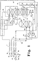
- Fig. 1 is a schematic flow diagram of one preferred embodiment of the cryogenic rectification system of the invention wherein vapor from the first intermediate heat exchanger is turboexpanded prior to being passed into the higher pressure column.
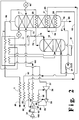
- Fig. 2 is a schematic flow diagram of another preferred embodiment of the cryogenic rectification system of the invention wherein a feed air stream is turboexpanded to generate refrigeration and then passed into the lower pressure column.
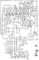
- FIG. 3 is a schematic flow diagram of another preferred embodiment of the cryogenic rectification system of the invention wherein feed air at two pressure levels is provided into the higher pressure column and wherein vapor from the first intermediate heat exchanger is condensed prior to being passed into the higher pressure column.
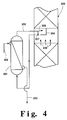
- Figure 4 is a representation of a preferred heat exchange arrangement in the practice of the invention wherein the defined heat exchange within a column takes place outside the column shell.
- the invention serves to more nearly eliminate the irreversibilities in the cryogenic distillation system of the lower pressure column of an air boiling system. This reduces the system energy requirements to a greater degree than is possible with conventional practice.
- By partially condensing a lower pressure feed air stream to reboil the lower pressure column the operating line of this section of the column is brought closer to the equilibrium line thus reducing the energy requirements of the system.
- feed air 100 is compressed to a pressure generally within the range of from 40 to 100 pounds per square inch absolute (psia) by passage through base load compressor 32 and resulting feed air stream 60 is cleaned of high boiling impurities such as water vapor and carbon dioxide by passage through purifier 50.
- a portion 87 of cleaned, compressed feed air 86 is withdrawn from the feed air, compressed by passage through booster compressor 32 to a pressure within the range of from 50 to 1200 psia and passed as resulting feed air stream 89 into main heat exchanger 1 wherein it is cooled by indirect heat exchange with return streams.
- Resulting feed air stream 102 is then passed through valve 101 and into first or higher pressure column 10 which is operating within the range of from 35 to 100 psia.
- a second portion 88 comprising from about 60 to 85 percent of the feed air, is cooled by passage through main heat exchanger 1, and resulting stream 63 is passed into bottom reboiler 20 wherein it is partially condensed by indirect heat exchange with reboiling bottom liquid within second or lower pressure column 11 which is operating at a pressure less than that of column 10 and generally within the range of from 15 to 35 psia.
- the partial condensation within bottom reboiler 20 results in a first vapor air portion, which has a nitrogen concentration exceeding that of feed air 63, and in a first liquid having an oxygen concentration which exceeds that of feed air 63.
- first vapor air portion and the first liquid are not separated but, rather, are passed in two phase stream 64 into first intermediate heat exchanger 21 which is located within lower pressure column 11 above, generally about 1 to 10 equilibrium stages above, bottom reboiler 20.
- first intermediate heat exchanger 21 the first vapor air portion is partially condensed by indirect heat exchange with vaporizing, preferably partially vaporizing, liquid flowing down column 11 thereby generating upflow vapor for column 11 and producing a second vapor air portion, which has a nitrogen concentration exceeding that of the first vapor air portion, and oxygen-enriched liquid air which has an oxygen concentration exceeding that of the first vapor air portion.
- the oxygen-enriched liquid air mixes with the first liquid and is passed along with the second vapor air portion in two phase stream 65 from first intermediate heat exchanger 21 into phase separator 40.
- Second vapor air portion is withdrawn from phase separator 40 as stream 67, turboexpanded by passage through turboexpander 30 and then passed as turboexpanded stream 70 into higher pressure column 10.
- Oxygen-enriched liquid is withdrawn from phase separator 40 as stream 66 passed through valve 99 and passed as stream 91 through heat exchanger 2 and valve 93 into lower pressure column 11 above, generally from 5 to 25 equilibrium stages above, first intermediate heat exchanger 21.
- stream 66 is combined with oxygen-enriched fluid from higher pressure column 10 to form stream 91.
- oxygen-enriched fluid is withdrawn from column 10 as liquid in stream 71 and passed into column 11, preferably as discussed earlier in combination with stream 66 in combined stream 91.
- Nitrogen-enriched fluid is withdrawn from column 10 as vapor stream 72 and passed into condenser 23 which is located within column 11 above, preferably from 1 to 20 equilibrium stages above, first intermediate heat exchanger 21.
- condenser 23 the nitrogen-enriched vapor is condensed by indirect heat exchanger with downflowing column liquid to produce column upflow vapor.
- Resulting nitrogen-enriched liquid is withdrawn from condenser 23 as stream 73.
- a portion 74 of nitrogen-enriched liquid 73 is passed into the upper portion of column 10 as reflux.
- Another portion 75 of stream 73 is passed through heat exchanger 2 and valve 77 and into the upper portion of column 11 as reflux.
- Nitrogen-rich vapor is withdrawn from the upper portion of column 11 as stream 96, warmed by passage through heat exchangers 2 and 1, and passed out of the system as stream 98, which may be recovered as product nitrogen.
- Lower purity oxygen is withdrawn from the lower portion of column 11 and recovered. In the embodiment illustrated in Figure 1, lower purity oxygen is withdrawn from column 11 as stream 79. If desired, a portion 80 of stream 79 may be recovered as product liquid lower purity oxygen. Another portion 81 of stream 79 is increased in pressure by passage through liquid pump 34 to form pressurized liquid lower purity oxygen stream 82 which is vaporized by passage through main heat exchanger 1. Resulting stream 83 is recovered as pressurized gaseous lower purity oxygen product.
- Figure 2 illustrates another embodiment of the invention wherein refrigeration of the system is supplied by the turboexpansion of a portion of the feed air.
- the numerals in Figure 2 correspond to those of Figure 1 for the common elements and these common elements will not be discussed again in detail.
- feed air stream 89 is divided upstream of main heat exchanger 1 into first portion 102, which is passed through heat exchanger 2 and into first or higher pressure column 10, and into third portion 68 which is further compressed by passage through compressor 35.
- Resulting further third compressed feed air portion 69 which comprises from about 5 to 15 percent of the total feed air, is cooled by partial traverse of main heat exchanger 1 and thereafter turboexpanded by passage through feed air turboexpander 36 to generate refrigeration.
- Resulting turboexpanded feed air stream 37 is then passed into second or lower pressure column 11.
- two phase stream 65 is not passed into a phase separator. Rather the entire stream is passed into the lower portion of higher pressure column 10. The liquid portion of stream 65 mixes with oxygen-enriched liquid at the bottom of column 10 and then is passed as combined stream 91 into column 11.
- Figure 3 illustrates another embodiment of the invention.
- the numerals of Figure 3 correspond to those of Figures 1 and 2 for the common elements and the common elements will not be discussed again in detail.
- feed air stream 86 is divided into first portion 125, which is cooled by passage through main heat exchanger 1 and passed into first or higher pressure column 10, and into feed air stream 126 which is compressed by passage through compressor 33 to form compressed stream 127.
- Stream 127 is divided into third feed air portion 69 and into stream 128 which is further divided into feed air streams 129 and 130.
- Stream 130 is further compressed through compressor 131 to form further compressed stream 132 which is cooled by passage through main heat exchanger 1 and passed through valve 133 into higher pressure column 10.
- Feed air stream 129 is cooled by passage through main heat exchanger 1 and divided into portion 134, which is passed through heat exchanger 2 and into column 10, preferably combined with stream 132, and into stream 63 which is the second portion of the feed air and which is passed into bottom reboiler 20.
- two phase stream 64 is passed into phase separator 41 and only first vapor air portion in stream 25 is passed into first intermediate heat exchanger 21.
- First liquid is passed in stream 26 through valve 98 and combined with oxygen -enriched liquid air stream 66 and oxygen-enriched liquid 71 to form stream 91.
- second vapor air portion 67 is passed through second intermediate heat exchanger 22 which is located within lower pressure column 11 above, preferably from 1 to 10 equilibrium stage above, first intermediate heat exchanger 21.
- the second vapor air portion is condensed within second intermediate heat exchanger 22 by indirect heat exchange with downflowing liquid to provide column vapor upflow.
- Resulting condensed second vapor air portion 76 is passed from second intermediate heat exchanger 22 through valve 177 and into column 10.
- Figures 1, 2 and 3 illustrate the heat exchange associated with heat exchangers 21,22 and 23 as occurring physically within the shell of the lower pressure column, this is done to simplify the illustration of the method of the invention. In many instances it is expected that one or more such heat exchangers will be located physically outside the shell of the lower pressure column, i.e. functionally within the column.
- Figure 4 illustrates one arrangement in generalized form of such a heat exchanger functionally within the column.
- Liquid stream 204 is introduced to heat exchanger 201 which may be a brazed aluminum heat exchanger. As liquid 204 traverses heat exchanger 201, it is at least partially vaporized by indirect heat exchange with a fluid 202 which is at least partially condensed. Fluid 202 represents the vapor flow into the heat exchanger, e.g. stream 64 or stream 72 of Figure 1. Streams 202 and 204 flow in a counter-current fashion within heat exchanger 201.
- Partially vaporized liquid 205 exits heat exchanger 201 and is delivered back to lower pressure column 200.
- the partially vaporized liquid is returned to the column in such a fashion that the vapor portion 206 is able to mix with vapor 209 rising within the lower pressure column from below the point where liquid 204 was originally withdrawn.
- the means for accomplishing this are commonly employed in distillation column design when a two-phase stream is introduced to an intermediate location within the column.
- the liquid portion 207 of stream 205 is disengaged from the vapor portion and is preferably distributed to those mass transfer elements such as packing or trays immediately below the level from where liquid 204 was originally withdrawn.
- the means for disengaging the liquid from the vapor and for distributing the liquid as described are commonly employed in distillation column design.
- stream 202 is at least partially condensed by the heat exchange within heat exchanger 201.
- Resulting fluid in stream 203 is passed into a column.
- Stream 203 corresponds, for example, to stream 65 or stream 73 of Figure 1.
Landscapes
- Engineering & Computer Science (AREA)
- Physics & Mathematics (AREA)
- Mechanical Engineering (AREA)
- Thermal Sciences (AREA)
- General Engineering & Computer Science (AREA)
- Health & Medical Sciences (AREA)
- Emergency Medicine (AREA)
- Separation By Low-Temperature Treatments (AREA)
Applications Claiming Priority (2)
| Application Number | Priority Date | Filing Date | Title |
|---|---|---|---|
| US08/618,380 US5611219A (en) | 1996-03-19 | 1996-03-19 | Air boiling cryogenic rectification system with staged feed air condensation |
| US618380 | 1996-03-19 |
Publications (2)
| Publication Number | Publication Date |
|---|---|
| EP0797061A2 true EP0797061A2 (de) | 1997-09-24 |
| EP0797061A3 EP0797061A3 (de) | 1998-05-20 |
Family
ID=24477460
Family Applications (1)
| Application Number | Title | Priority Date | Filing Date |
|---|---|---|---|
| EP97101484A Withdrawn EP0797061A3 (de) | 1996-03-19 | 1997-01-30 | Luftkochendes kryogenisches Rektifikationssystem mit stufenweiser Luftkondensation |
Country Status (6)
| Country | Link |
|---|---|
| US (1) | US5611219A (de) |
| EP (1) | EP0797061A3 (de) |
| KR (1) | KR100289109B1 (de) |
| BR (1) | BR9700820A (de) |
| CA (1) | CA2196354C (de) |
| ID (1) | ID19780A (de) |
Families Citing this family (12)
| Publication number | Priority date | Publication date | Assignee | Title |
|---|---|---|---|---|
| US6170264B1 (en) | 1997-09-22 | 2001-01-09 | Clean Energy Systems, Inc. | Hydrocarbon combustion power generation system with CO2 sequestration |
| US5680764A (en) * | 1995-06-07 | 1997-10-28 | Clean Energy Systems, Inc. | Clean air engines transportation and other power applications |
| US5836175A (en) * | 1997-08-29 | 1998-11-17 | Praxair Technology, Inc. | Dual column cryogenic rectification system for producing nitrogen |
| US5839296A (en) * | 1997-09-09 | 1998-11-24 | Praxair Technology, Inc. | High pressure, improved efficiency cryogenic rectification system for low purity oxygen production |
| US5806342A (en) * | 1997-10-15 | 1998-09-15 | Praxair Technology, Inc. | Cryogenic rectification system for producing low purity oxygen and high purity oxygen |
| US5921108A (en) * | 1997-12-02 | 1999-07-13 | Praxair Technology, Inc. | Reflux condenser cryogenic rectification system for producing lower purity oxygen |
| US5896755A (en) * | 1998-07-10 | 1999-04-27 | Praxair Technology, Inc. | Cryogenic rectification system with modular cold boxes |
| US6173586B1 (en) * | 1999-08-31 | 2001-01-16 | Praxair Technology, Inc. | Cryogenic rectification system for producing very high purity oxygen |
| US7549301B2 (en) * | 2006-06-09 | 2009-06-23 | Praxair Technology, Inc. | Air separation method |
| US8286446B2 (en) * | 2008-05-07 | 2012-10-16 | Praxair Technology, Inc. | Method and apparatus for separating air |
| CA2694654C (en) * | 2009-03-13 | 2016-01-26 | Conocophillips Company | Hydrocarbon production process |
| FR2974890A1 (fr) * | 2009-05-13 | 2012-11-09 | Air Liquide | Procede et appareil de separation d'air par distillation cryogenique. |
Family Cites Families (20)
| Publication number | Priority date | Publication date | Assignee | Title |
|---|---|---|---|---|
| NL102363C (de) * | 1953-11-12 | |||
| US3210951A (en) * | 1960-08-25 | 1965-10-12 | Air Prod & Chem | Method for low temperature separation of gaseous mixtures |
| US3113854A (en) * | 1960-08-25 | 1963-12-10 | Air Prod & Chem | Method and apparatus for separating gaseous mixtures |
| US3327489A (en) * | 1960-08-25 | 1967-06-27 | Air Prod & Chem | Method for separating gaseous mixtures |
| JPS56124879A (en) * | 1980-02-26 | 1981-09-30 | Kobe Steel Ltd | Air liquefying and separating method and apparatus |
| US4410343A (en) * | 1981-12-24 | 1983-10-18 | Union Carbide Corporation | Air boiling process to produce low purity oxygen |
| US4796431A (en) * | 1986-07-15 | 1989-01-10 | Erickson Donald C | Nitrogen partial expansion refrigeration for cryogenic air separation |
| US4702757A (en) * | 1986-08-20 | 1987-10-27 | Air Products And Chemicals, Inc. | Dual air pressure cycle to produce low purity oxygen |
| US4704148A (en) * | 1986-08-20 | 1987-11-03 | Air Products And Chemicals, Inc. | Cycle to produce low purity oxygen |
| US4769055A (en) * | 1987-02-03 | 1988-09-06 | Erickson Donald C | Companded total condensation reboil cryogenic air separation |
| US4775399A (en) * | 1987-11-17 | 1988-10-04 | Erickson Donald C | Air fractionation improvements for nitrogen production |
| US4895583A (en) * | 1989-01-12 | 1990-01-23 | The Boc Group, Inc. | Apparatus and method for separating air |
| US5315833A (en) * | 1991-10-15 | 1994-05-31 | Liquid Air Engineering Corporation | Process for the mixed production of high and low purity oxygen |
| FR2685459B1 (fr) * | 1991-12-18 | 1994-02-11 | Air Liquide | Procede et installation de production d'oxygene impur. |
| GB9212224D0 (en) * | 1992-06-09 | 1992-07-22 | Boc Group Plc | Air separation |
| FR2701313B1 (fr) * | 1993-02-09 | 1995-03-31 | Air Liquide | Procédé et installation de production d'azote ultra-pur par distillation d'air. |
| US5379598A (en) * | 1993-08-23 | 1995-01-10 | The Boc Group, Inc. | Cryogenic rectification process and apparatus for vaporizing a pumped liquid product |
| GB9325648D0 (en) * | 1993-12-15 | 1994-02-16 | Boc Group Plc | Air separation |
| US5467602A (en) * | 1994-05-10 | 1995-11-21 | Praxair Technology, Inc. | Air boiling cryogenic rectification system for producing elevated pressure oxygen |
| US5551258A (en) * | 1994-12-15 | 1996-09-03 | The Boc Group Plc | Air separation |
-
1996
- 1996-03-19 US US08/618,380 patent/US5611219A/en not_active Expired - Fee Related
-
1997
- 1997-01-29 ID IDP970265A patent/ID19780A/id unknown
- 1997-01-30 EP EP97101484A patent/EP0797061A3/de not_active Withdrawn
- 1997-01-30 CA CA002196354A patent/CA2196354C/en not_active Expired - Fee Related
- 1997-01-30 BR BR9700820A patent/BR9700820A/pt not_active Application Discontinuation
- 1997-01-30 KR KR1019970002752A patent/KR100289109B1/ko not_active Expired - Fee Related
Also Published As
| Publication number | Publication date |
|---|---|
| CA2196354A1 (en) | 1997-09-20 |
| CA2196354C (en) | 2000-01-25 |
| US5611219A (en) | 1997-03-18 |
| ID19780A (id) | 1998-07-30 |
| BR9700820A (pt) | 1998-07-07 |
| KR970066476A (ko) | 1997-10-13 |
| EP0797061A3 (de) | 1998-05-20 |
| KR100289109B1 (ko) | 2001-05-02 |
Similar Documents
| Publication | Publication Date | Title |
|---|---|---|
| EP0674144B1 (de) | Kryogenisches Rektifikationsverfahren zur Herstellung von Hochdruckstickstoff | |
| US5463871A (en) | Side column cryogenic rectification system for producing lower purity oxygen | |
| US6626008B1 (en) | Cold compression cryogenic rectification system for producing low purity oxygen | |
| US5337570A (en) | Cryogenic rectification system for producing lower purity oxygen | |
| EP0594214B1 (de) | Kryogenisches Rektifikationsverfahren mit thermisch integrierter Argonkolonne | |
| US5678427A (en) | Cryogenic rectification system for producing low purity oxygen and high purity nitrogen | |
| US5611219A (en) | Air boiling cryogenic rectification system with staged feed air condensation | |
| US5467602A (en) | Air boiling cryogenic rectification system for producing elevated pressure oxygen | |
| US5669236A (en) | Cryogenic rectification system for producing low purity oxygen and high purity oxygen | |
| EP0936429B1 (de) | Kryogenisches Rektifikationsystem zur Herstellung von ultrahochreinem Stickstoff und ultrahochreinem Sauerstoff | |
| US5682766A (en) | Cryogenic rectification system for producing lower purity oxygen and higher purity oxygen | |
| EP0563800A1 (de) | Kryogenisches Rektifikationsverfahren mit hoher Rückgewinnung | |
| US5916262A (en) | Cryogenic rectification system for producing low purity oxygen and high purity oxygen | |
| US5832748A (en) | Single column cryogenic rectification system for lower purity oxygen production | |
| EP0824209B1 (de) | Kryogenisches Rektifikationssystem mit Seitenkolonne zur Herstellung von Sauerstoff niedrigerer Reinheit und hochreinem Stickstoff | |
| US5666824A (en) | Cryogenic rectification system with staged feed air condensation | |
| US6622520B1 (en) | Cryogenic rectification system for producing low purity oxygen using shelf vapor turboexpansion | |
| US5467601A (en) | Air boiling cryogenic rectification system with lower power requirements | |
| US5878597A (en) | Cryogenic rectification system with serial liquid air feed | |
| EP0848219B1 (de) | Kryogenisches Rektifikationssystem zur Herstellung von Argon und Sauerstoff niedriger Reinheit | |
| US5873264A (en) | Cryogenic rectification system with intermediate third column reboil | |
| US6073462A (en) | Cryogenic air separation system for producing elevated pressure oxygen |
Legal Events
| Date | Code | Title | Description |
|---|---|---|---|
| PUAI | Public reference made under article 153(3) epc to a published international application that has entered the european phase |
Free format text: ORIGINAL CODE: 0009012 |
|
| AK | Designated contracting states |
Kind code of ref document: A2 Designated state(s): DE ES FR GB IT |
|
| PUAL | Search report despatched |
Free format text: ORIGINAL CODE: 0009013 |
|
| AK | Designated contracting states |
Kind code of ref document: A3 Designated state(s): DE ES FR GB IT |
|
| 17P | Request for examination filed |
Effective date: 19980528 |
|
| 17Q | First examination report despatched |
Effective date: 20000510 |
|
| STAA | Information on the status of an ep patent application or granted ep patent |
Free format text: STATUS: THE APPLICATION IS DEEMED TO BE WITHDRAWN |
|
| 18D | Application deemed to be withdrawn |
Effective date: 20010216 |