EP0796939B1 - Piezoelektrische Nadelauswahlvorrichtung für Strickmaschinen - Google Patents
Piezoelektrische Nadelauswahlvorrichtung für Strickmaschinen Download PDFInfo
- Publication number
- EP0796939B1 EP0796939B1 EP97301793A EP97301793A EP0796939B1 EP 0796939 B1 EP0796939 B1 EP 0796939B1 EP 97301793 A EP97301793 A EP 97301793A EP 97301793 A EP97301793 A EP 97301793A EP 0796939 B1 EP0796939 B1 EP 0796939B1
- Authority
- EP
- European Patent Office
- Prior art keywords
- selector
- knitting machine
- selector jacks
- jacks
- needles
- Prior art date
- Legal status (The legal status is an assumption and is not a legal conclusion. Google has not performed a legal analysis and makes no representation as to the accuracy of the status listed.)
- Expired - Lifetime
Links
Images


Classifications
-
- D—TEXTILES; PAPER
- D04—BRAIDING; LACE-MAKING; KNITTING; TRIMMINGS; NON-WOVEN FABRICS
- D04B—KNITTING
- D04B15/00—Details of, or auxiliary devices incorporated in, weft knitting machines, restricted to machines of this kind
- D04B15/66—Devices for determining or controlling patterns ; Program-control arrangements
- D04B15/68—Devices for determining or controlling patterns ; Program-control arrangements characterised by the knitting instruments used
- D04B15/78—Electrical devices
-
- H—ELECTRICITY
- H10—SEMICONDUCTOR DEVICES; ELECTRIC SOLID-STATE DEVICES NOT OTHERWISE PROVIDED FOR
- H10N—ELECTRIC SOLID-STATE DEVICES NOT OTHERWISE PROVIDED FOR
- H10N30/00—Piezoelectric or electrostrictive devices
- H10N30/20—Piezoelectric or electrostrictive devices with electrical input and mechanical output, e.g. functioning as actuators or vibrators
-
- H—ELECTRICITY
- H10—SEMICONDUCTOR DEVICES; ELECTRIC SOLID-STATE DEVICES NOT OTHERWISE PROVIDED FOR
- H10N—ELECTRIC SOLID-STATE DEVICES NOT OTHERWISE PROVIDED FOR
- H10N30/00—Piezoelectric or electrostrictive devices
- H10N30/80—Constructional details
- H10N30/802—Circuitry or processes for operating piezoelectric or electrostrictive devices not otherwise provided for, e.g. drive circuits
Definitions
- the present invention relates to knitting machines and, more particularly, to a needle selection device for knitting machines.
- the present invention relates to an a knitting machine having improved electronic pattern device and, more specifically, to an improved piezoelectric pattern device.
- a piezoelectric device to control needle selection members of a knitting pattern mechanism.
- a typical such piezoelectric pattern mechanism is disclosed in DE-A-3 933 149.
- This pattern mechanism includes a piezoelectric body having a piezoelectric element, which moves upwardly and downwardly upon application of a voltage thereto.
- the front end of the piezoelectric body is linked to a movably mounted finger and the piezoelectric body and the finger are arranged in a straight line.
- the rear end of the piezoelectric body is supported within a groove in a supporting housing and the medial portion of the piezoelectric body is held by a rotating member rotatably mounted on the supporting housing.
- the needles move between three operating positions, i.e. knit, tuck and welt positions.
- the piezoelectric pattern mechanisms required that the fingers be divided into left and right rows, with one row of fingers for selecting those needles to be moved to the welt position and the other row of fingers for selecting those needles to be moved to the tuck position. If one row has eight fingers, for example, the other row also must have eight fingers, resulting in two rows with a total of sixteen fingers arranged in a zigzag pattern.
- the large number of fingers required creates significant problems because the number of piezoelectric bodies, and the number of other components and wiring, increase proportionately to the number of fingers.
- the piezoelectric bodies of both rows must have the same capacity, inevitably requiring a large pattern mechanism.
- the present invention consists in a knitting machine including knitting needles movable between knit, tuck and welt positions to form stitch loops in a predetermined pattern, and pattern controlled needle selection means for selecting particular needles to be moved to and between the knit, tuck and welt positions in accordance with said pattern, characterized in that said needle selection means includes a piezoelectric body movable between three operative positions corresponding to the knit, tuck and welt positions of said needles, first driving means for causing said piezoelectric body to move to one of its operative positions, second driving means for causing said piezoelectric body to move to another one of its operative positions, and third driving means for causing said piezoelectric body to move to the remaining one of its operative positions, whereby said piezoelectric body selects and causes a needle to move between its three operative positions in accordance with said predetermined pattern.
- the piezoelectric pattern mechanism may require only a single row of fingers, each of which is capable of selecting any one of the three operating positions of the knitting needles.
- the needle selection means includes a first driving means which causes the piezoelectric body to displace upwardly, a second driving means which causes the piezoelectric body to displace downwardly, and a third driving means for causing the piezoelectric body to displace to the neutral position.
- the needle selection means is combined with a needle mechanism of a knitting machine in which individual needles are selected by selector jacks which in turn operate spring jacks. Such selector jacks and spring jacks are disclosed in US-A-Patent No 4 604 877.
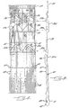
- Knitting machine 20 includes a needle cylinder 21 having a multiplicity of grooves 21a in the outer periphery thereof.
- a knitting needle 22 is slidably mounted for vertical movement between three operation positions, i.e. knit, tuck and welt positions.
- Knitting machine 20 further includes a cam supporting block 23 which is carried by an upper cam ring 24.
- Upper cam ring 24 is in turn supported on a lower cam ring 25.
- a stitch cam 26 is supported on the inner face of cam block 23 and includes a cam race 26a.
- Cam race 26a receives an operating butt 22a of needle 22 to move needle 22 upwardly and downwardly in accordance with a predetermined pattern.
- a spring jack 30 is disposed in each groove 21a of the needle cylinder 21 below each needle 22.
- Spring jack 30 is substantially identical to the spring jack described in our JP-A-8199453 or US-A-5 647 230. Accordingly, spring jack 30 will not be described in detail herein except as is necessary for an understanding of the operation thereof.
- Spring jack 30 includes a raising butt 30a, a lowering butt 30b and a lower portion or tail 30c. Spring jack 30 also includes an offset upper portion 30d, which overlaps the lower end of needle 22 and defines with butt 30a a shoulder for contacting the lower end of needle 22 .
- Cam block 23 carries a raising cam 31 having a cam race 31a cooperating with butt 30a and a lowering cam 32 having a cam race 32a cooperating with lowering butt 30b.
- a selector jack is mounted in each groove 21a of cylinder 21 beneath spring jack 30.
- the upper end portion 40a of the selector jack overlaps the lower portion or tail 30c of spring jack 30.
- Selector jack 40 is also described substantially in our aforementioned Japanese and US Patent Specifications.
- Selector jack 40 has a first pivot portion 41 which contacts the bottom of the groove 21a and a V-shaped projection 42 at the lower end thereof.
- a pair of coil girdle springs 43 biases the lower portion of selector jack 40 toward the bottom of the groove 21a, while permitting limited upward and downward movement of the selector jack 40 in the groove 21a.
- a stop plate 45 is mounted on upper cam ring 24 and limits the outward movement of the selector jack 40 to maintain the upper end portion 46 of selector jack 40 in position and in contact with the tail 30c of spring jack 30.
- Selector jack 40 includes a master butt 47 and a pattern butt 48 below the master butt 47 (Figure 9). Master butts 47 are respectively at the same level from selector jack to selector jack, while pattern butts 48 on adjacent selector jacks form a row of butts arranged diagonally and with a clearance with each other ( Figure 8).
- the selector jacks 40 may be formed of a relatively thin or narrow elastic or flexible member so as to alleviate the shock that is generated during operation of the knitting machine 20.
- the lower cam ring 25 supports a selector jack supporting member 44 for receipt of the V-shaped projection 42 of selector jack 40.
- Selector jack supporting member 44 preferably has a V-shaped groove 44a therein ( Figure 10) to receive the V-shaped projection 42.
- V-shaped groove 44a and V-shaped projection 42 thusly maintain the selector jack 40 at a certain level in normal operation.
- supporting member 44 may be provided with an upper sloping surface 44b and a lower sloping surface 44c to stabilize better the position of the selector jack 40 which has been moved up or down in a manner to be presently described.
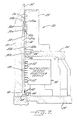
- a piezoelectric needle selecting device, generally indicated at 50 (Figure 7) is carried by lower cam ring 25 adjacent the path of travel of the selector jacks 40 as they travel with cylinder 21 as it rotates.
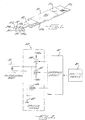
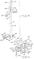
- Piezoelectric needle selecting device 50 includes a plurality of piezoelectric bodies 51 ( Figure 1).
- the piezoelectric bodies 51 are identical and, therefore, only one will be described.
- the piezoelectric body 51 ( Figure 1) includes a plate member 51a having piezoelectric elements 51b and 51c attached to opposite sides thereof. These piezoelectric elements may be, for example, a bimorph-type ceramic actuator.
- a finger 52 is coupled to the outer end of the plate member 51a of piezoelectric body 51 in a movable manner.
- Finger 52 carries an actuating head, generally indicated at 53, at its outer end for selective engagement with pattern butt 48 of selector jack 40.
- Each actuating head 53 includes a front end face 54 having an inwardly sloping surface 54a and a vertical surface 54b downstream of inwardly sloping surface 54a.
- Actuating head 53 also includes an upper face 55 having an upwardly sloping surface 55a and an upper horizontal surface 55b.
- Actuating head 53 has a comparable lower face 56 with a downwardly sloping surface 56a and a horizontal surface 56b downstream thereof.
- the pattern butt 48 of a selector jack 40 will contact one of these three faces 54, 55 or 56 and the selector jack 40 will thus be moved inwardly if face 54 is contacted, upwardly if face 55 is contacted or downwardly if face 56 is contacted.
- a cancelling cam 57 is provided in the path of the master butts 47 to ensure that each selector jack 40 is properly positioned for the piezoelectric needle selecting device 50 and the actuating head 53 ( Figures 15a, 15b and 15c).
- Actuating head 60 has a front face 61 having an inwardly sloping surface 61a, a bifurcated vertical surface 61b and an outwardly sloping surface 61c between the bifurcations of vertical surface 61b.
- Actuating head 60 also includes an upper face 62 having a first upwardly sloping surface 62a, a second upwardly sloping surface 62b downstream of the first upwardly sloping surface 62a and a horizontal surface 62c.
- Actuating head 60 has a corresponding lower face 63 having a first downwardly sloping surface 63a, a second downwardly sloping surface 63b and a horizontal surface 63c.
- actuating head 60 contacts pattern butt 48 of selector jack 40 and pattern butt 48 moves along inwardly sloping surface 61a which pushes the selector jack 40 inwardly. Butt 48 next contacts outwardly sloping surface 61c which gradually returns the selector jack 40 and spring jack 30 to their original positions while alleviating any shock which may be caused when butt 30b of spring jack 30 contacts raising cam 31 .
- selector jack 40 When finger 52' is either raised or lowered, butt 48 moves along the surface 62 or 63 and selector jack 40 is raised or lowered.
- the first sloping surface 62a or 63a moves the selector jack 40 upwardly or downwardly to the first step and the second sloping surface 62b or 63b moves the selector jack 40 upwardly or downwardly to the second step.
- the horizontal length of the second sloping surface 62b or 63b may be relatively short, which is effective for fine gauge knit fabrics which have a limited needle-selecting range.
- the upward or downward movement of the selector jacks 40 is assisted by the sloping surface 44b or 44a, respectively, of selector jack supporting member 44.
- a welt cam 70 and a tuck cam 71 are carried either by the lower cam ring 25 or the upper cam ring 24 by suitable supports (not shown).
- Cam 70 includes an inwardly sloping surface 70a and a horizontal surface 70b ( Figures 10 and 13).
- Cam 71 also has an inwardly sloping surface 71a and a horizontal surface 71b.
- cams 70 and 71 are mounted at different heights relative to the master butt 47 of the selector jack 40 such that neither of these cams are contacted by the master butt 47 when the piezoelectric body 51 is in the neutral position and cam 70 is contacted by the master butt 47 when the piezoelectric body 51 is displaced downwardly and cam 71 is contacted thereby when the piezoelectric body 50 is displaced upwardly.
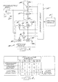
- Control system 80 includes a control means 81, an interface circuit 82 and driving means, generally indicated at 83.
- Driving means 83 includes a first driving or switching means 84 (labeled D 1 ), which may be a first transistor circuit, a second driving or switching means 85 (labeled D 2 ), which may be a second transistor circuit, and a third driving or switching means 86 (labeled D 3 ), which may be a third transistor circuit.
- the first, second and third switching means 84, 85 and 86 are all connected in parallel to the piezoelectric body 51.
- first switching means 84 is connected to a positive voltage of a first potential, for example, +48 volts and second switching means 85 is connected to a negative voltage of a second potential, for example, -48 volts. All three switching means are connected to ground as is indicated at 87.
- the control means 81 outputs, for example, three kinds of two-bit information signals, such as "0,0"; "1,0” and "0,1". These output signals are delivered to interface circuit 82 which converts the two-bit information signals to actuating signals for the first, second and third switching means 84, 85 and 86. For example, when information signal "0,0" is output from control means 81 to interface circuit 82 , interface circuit 82 outputs an actuating signal to open the first and second switching means 84 and 85 while third switching means 86 is closed and short circuits the piezoelectric body 51. Piezoelectric body 51 is caused to move to the neutral position.
- interface circuit 82 When information signal "1,0" is output, interface circuit 82 outputs an actuating signal to open the second and third switching means 85 and 86 while closing the first switching means 84. First switching means 84 then applies a positive voltage of, for example, +48 volts to the piezoelectric element 51b which causes the piezoelectric body 51 to be displaced upwardly. Similarly, when information signal "0,1" is output by control means 81, interface circuit 82 outputs an actuating signal to open the first and third switching means 84 and 86 while closing the second switching means 85 . Second switching means 85 applies a negative voltage of, for example, -48 volts to piezoelectric element 51a to cause piezoelectric body 51 to be displaced downwardly.
- a control means 81' is provided and outputs three two-bit information signals to an interface circuit 82'.
- Interface circuit 82' converts the two-bit information signals to actuating signals and outputs such actuating signals to a first switching means 84' (labeled T 1 ), a second switching means 85' (labeled T 2 ), and a driving means, generally indicated at 90.
- Driving means 90 includes first, second, and paired third and fourth switching means 91 (labeled T 3 ), 92 (labeled T 4 ) and 93 (labeled T 5 ), 94 (also labeled T 5 ). As before, all of these switching means 84', 85', 91, 92 and 93, 94 may be transistor circuits, and all are connected to the piezoelectric body 51 and to ground as indicated at 87'.
- Switching means 91 and 93 are connected in series, as are switching means 92, 94.
- a capacitance means which may be a pair of capacitors 95, 96 are connected across the series connected switching means 91, 93 and 92, 94.
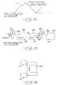
- control means 81' When control means 81' outputs an information signal "0,0", interface circuit 82' outputs an actuating signal to switch off switching means 84', 85', 93 and 94 and switches the switching means 91 and 92 on and off quickly and alternately.
- the capacitors 95, 96 which have been precharged, are discharged. As shown in Figure 6, positive (+) and negative (-) voltages are alternately applied, resulting in a more neutral condition ( Figure 5a) .
- interface circuit 82' When information signal "1,0" is output by control means 81', interface circuit 82' outputs an actuating signal to switch on the switching means 84' and switch off the switching means 85', 91 and 92. Switching means 93 and 94 are switched on to charge the capacitors 95 and 96. Switching means 84' applies a positive voltage of, for example, +48 volts to piezoelectric body 51 causing the front end thereof to displace downwardly ( Figure 5c).
- interface circuit 82' When control means 81' outputs the information signal "0,1", interface circuit 82' outputs an actuating signal to switch on the switching means 85' and switch off the switching means 84', 91 and 92 and to switch on the switching means 93, 94 to charge the capacitors 95, 96.
- Switching means 85' applies a negative voltage of, for example, -48 volts to piezoelectric body 51 to cause the front end thereof to displace upwardly ( Figure 5b).
- Figure 4 is a table which correlates the three operational positions of the piezoelectric body 51 and the operating conditions of the transistor circuits or switching means 84', 85', 91, 92, 93 and 94 (labeled T 1 , T 2 , T 3 , T 4 and T 5 , T 5 ).
- a pre-programmed pattern device causes the control means 81 or 81' to output the requisite two-bit information signals to cause the piezoelectric body 51 to occupy a particular position of its three operating positions to achieve a corresponding movement of the knitting needle 22 to the knit, tuck or welt position as is necessary to duplicate the pattern to be knit. If the pattern calls for the needle 22 to be moved to the knit position, the piezoelectric body 51 is caused to move to the neutral position ( Figure 5a) in a manner previously described.
- the selector jack 40 is not raised or lowered but the pattern butt 48 thereof engages and moves along the front face 54 or 61 of the finger 53 or 60 which pivots the selector jack 40 inwardly. 2ne master butt 47 of the selector jack 40 passes between the cams 70 and 71 and the spring jack 30 is raised by cams 32 to raise needle 22. Needle 22 is then raised by stitch cam 26 to the knit position.
- the piezoelectric body 51 is caused to move downwardly (Figure 5c) so that pattern butt 48 on the selector jack 40 engages and moves along upper face 55 or 62 of actuating head 53 or 60 to raise selector jack 40 upwardly and to cause master butt 47 to engage the tuck cam 71.
- Tuck cam 71 moves selector jack 40 inwardly and causes spring jack 30 to be moved by cam 32 to the tuck position and correspondingly to cause needle 22 to be moved to the tuck position by stitch cam 26.
- Needle 22 is moved to the welt position by piezoelectric body 51 moving upwardly which causes pattern butt 48 to engage and move along the lower face 56 or 63 of head 53 or 60 to move the selector jack 40 downwardly
- Welt cam 70 will then force selector jack 40 inwardly which will cause spring jack 30 to engage the welt cam track of cam 32 and thus needle 22 to engage the welt cam track of stitch cam 26.
- needle selection in accordance with a preprogrammed or predetermined pattern is accomplished using piezoelectric elements with only half of the usual number of fingers and actuating heads.
Landscapes
- Engineering & Computer Science (AREA)
- Textile Engineering (AREA)
- Knitting Machines (AREA)
Claims (13)
- Strickmaschine (20), umfassend Stricknadeln (22), die zwischen einer Strickposition, einer Fangposition und einer Randposition bewegbar sind, um Maschen in einem vorbestimmten Muster auszubilden, und mustergesteuerte Nadelauswahlmittel (50) zum Auswählen bestimmter Nadeln (22), um diese gemäß dem Muster zu der und zwischen den Strick-, Fang- und Randposition zu bewegen, dadurch gekennzeichnet, daß die Nadelauswahlmittel (50) umfassen:einen piezoelektrischen Körper (51), der zwischen drei Arbeitspositionen bewegbar ist, die der Strick-, Fang- und Randposition der Nadeln (22) entsprechen,erste Antriebsmittel (84) zum Veranlassen des piezoelektrischen Körpers (51), sich in eine seiner Arbeitspositionen zu bewegen,zweite Antriebsmittel (85) zum Veranlassen des piezoelektrischen Körpers (51), sich in eine andere seiner Arbeitspositionen zu bewegen, unddritte Antriebsmittel (86) zum Veranlassen des piezoelektrischen Körpers (51), sich in die verbleibende seiner Arbeitspositionen zu bewegen, wodurch der piezoelektrische Körper (51) eine Nadel (22) auswählt und sie veranlaßt, sich zwischen ihren drei Arbeitspositionen gemäß dem vorbestimmten Muster zu bewegen.
- Strickmaschine (20) nach Anspruch 1, wobei die Nadelauswahlmittel (50) Steuermittel (81) zur Abgabe dreier Steuersignale aufweist, um die ersten, zweiten und dritten Antriebsmittel (84, 85, 86) zu steuern.
- Strickmaschine (20) nach Anspruch 1 oder 2, wobei der piezoelektrische Körper (51) ein längliches Grundelement (51a) und zumindest ein piezoelektrisches Element (51b) aufweist, wobei das Element (51b) von dem Grundelement (51a) getragen wird und bei Anlegen einer Spannung eines ersten Potentials in eine erste Position, bei Anlegen einer Spannung eines zweiten Potentials , das unterschiedlich zum ersten Potential ist, in eine zweite Position, und bei Anlegen einer Spannung eines dritten Potentials, das zwischen dem ersten und dem zweiten Potential liegt, in eine dritte Position bewegbar ist.
- Strickmaschine (20) nach Anspruch 3, wobei das erste und das zweite Potential Spannungen von gleichem Wert, aber entgegengesetzter Polarität sind.
- Strickmaschine (20) nach Anspruch 3 oder 4, wobei das dritte Potential null ist.
- Strickmaschine (20) nach Anspruch 3 oder 4, wobei das dritte Potential Ausgangssignale entgegengesetzter Polarität von zwei Kondensatoren umfaßt, welche schnell und abwechselnd solange angelegt werden, bis die Kondensatoren auf null entladen sind.
- Strickmaschine nach Anspruch 1, einschließend Federheber (30), die mit den Stricknadeln (22) zum Bewegen der Stricknadeln (22) zwischen der Strickposition, der Fangposition und der Randposition betriebsfähig verbunden sind, und Auswahlheber (40) zum ausgewählten Betätigen der Federheber (30), um die Nadeln (22) zu bewegen, wobei die Nadelauswahlmittel (50) Betätigungsmittel (53, 60) zum Bewegen der Auswahlheber (40) nach innen, um die Nadeln (22) zu veranlassen, sich in die Strickposition zu bewegen, und zum Bewegen der Auswahlheber (40) nach oben und nach unten, um die Nadeln (22) zu veranlassen, sich in die Randposition und in die Fangposition zu bewegen, einschließen.
- Strickmaschine nach Anspruch 7, wobei jeder der Auswahlheber (40) ein Meisterendstück (47) und ein Musterendstück (48) darauf in Längsrichtung zueinander beabstandet aufweist und wobei das Betätigungsmittel einen Betätigungskopf (53, 60) aufweist, der eine vordere Nockenfläche (54, 61), eine obere Nockenfläche (55, 62) und eine untere Nockenfläche (56, 63) aufweist, die so angeordnet sind, um mit dem Musterendstück (48) auf dem Auswahlheber (40) in Eingriff zu gelangen, um den Auswahlheber (40) zu bewegen.
- Strickmaschine nach Anspruch 8, wobei die vordere Nockenfläche (54, 61) des Betätigungskopfs (53, 60) eine nach innen geneigte Oberfläche (54a, 61a) und eine horizontale Fläche (54b, 61 c) aufweist, wobei die obere Nockenflöche (55, 62) eine nach oben geneigte Fläche (55a, 62a, 62b) und eine horizontale Fläche (55b, 62c) aufweist und wobei die untere Nockenfläche (56, 63) eine nach unten geneigte Fläche (56a, 63a, 63b) und eine horizontale Fläche aufweist.
- Strickmaschine nach Anspruch 8 oder 9, enthaltend eine Löschnocke (57), die mit den Meisterendstücken (47) auf den Auswahlhebern (40) zum Rücksetzen aller Auswahlheber (40) in dieselbe Position oder Ebene in Eingriff bringbar ist, wenn sich die Auswahlheber (40) dem Betätigungsmittel (60) nähern.
- Strickmaschine nach Anspruch 8, 9 oder 10, enhaltend eine Oberrandnocke (70), die mit den Meisterendstücken (47) auf den Auswahlhebern (40) in Eingriff bringbar ist, wenn die Auswahlheber (40) durch das Betätigungsmittel (60)nach unten bewegt werden, um die Auswahlheber (40) in eine Position zu bewegen, die der Randposition der Nadeln (22) entspricht, und eine Fangnocke (71), die mit den Meisterendstücken (47) auf den Auswahlhebern (40) in Eingriff bringbar ist, wenn die Auswahlheber (40) durch das Betätigungsmittel (61)nach oben bewegt werden, um die Auswahlheber (40) in eine Position zu bewegen, die der Fangposition der Nadeln (22) entspricht.
- Strickmaschine nach einem der Ansprüche 7 bis 11, wobei jeder der Auswahlheber (40) einen seitlichen Fortsatz (42) an seinem unteren Ende aufweist und wobei das Auswahlheberstützmittel (44) mit den Fortsätzen (42) in Eingriff bringbar ist, um die Auswahlheber (40) auf einer bestimmten Höhe zu halten, wenn die Auswahlheber (40) durch das Betätigungsmittel (60) nach innen bewegt werden, und um die Auswahlheber (40) beim Bewegen nach oben und unten zu unterstützen, um die Auswahlheber (40) in stabilen Positionen zu halten.
- Strickmaschine nach einem der Ansprüche 7 bis 12, wobei die Auswahlheber (40) in einem mittigen Schaftabschnitt federnd sind.
Applications Claiming Priority (3)
| Application Number | Priority Date | Filing Date | Title |
|---|---|---|---|
| JP8090435A JPH09256252A (ja) | 1996-03-19 | 1996-03-19 | 圧電体の制御装置、およびこれを有する編みツール制御装置 |
| JP9043596 | 1996-03-19 | ||
| JP90435/96 | 1996-03-19 |
Publications (2)
| Publication Number | Publication Date |
|---|---|
| EP0796939A1 EP0796939A1 (de) | 1997-09-24 |
| EP0796939B1 true EP0796939B1 (de) | 2001-10-17 |
Family
ID=13998537
Family Applications (1)
| Application Number | Title | Priority Date | Filing Date |
|---|---|---|---|
| EP97301793A Expired - Lifetime EP0796939B1 (de) | 1996-03-19 | 1997-03-18 | Piezoelektrische Nadelauswahlvorrichtung für Strickmaschinen |
Country Status (6)
| Country | Link |
|---|---|
| US (1) | US5823015A (de) |
| EP (1) | EP0796939B1 (de) |
| JP (1) | JPH09256252A (de) |
| KR (1) | KR970067964A (de) |
| DE (1) | DE69707331T2 (de) |
| TW (1) | TW359699B (de) |
Families Citing this family (17)
| Publication number | Priority date | Publication date | Assignee | Title |
|---|---|---|---|---|
| AU2711697A (en) * | 1997-05-15 | 1998-12-08 | Nanomotion Ltd. | Knitting machine |
| WO1999034048A1 (en) * | 1997-12-24 | 1999-07-08 | Nanomotion Ltd. | Selector for knitting machine |
| ITTO980484A1 (it) * | 1998-06-04 | 1999-12-04 | Matrix Spa | Dispositivo modulare di selezione piezoelettrica di elementi di coman- do, ad esempio gli aghi di una macchina tessile. |
| DE69921598T2 (de) * | 1998-06-25 | 2005-10-27 | Wac Data Service K.K., Fujimi | Nadelauswähler für strickmaschine |
| JP2000045156A (ja) | 1998-07-23 | 2000-02-15 | Precision Fukuhara Works Ltd | 編機の多段式電気制御選針装置 |
| JP2000054246A (ja) * | 1998-08-05 | 2000-02-22 | Precision Fukuhara Works Ltd | 編機の制御方法および制御装置 |
| DE29824221U1 (de) * | 1998-11-12 | 2000-09-14 | Drei-S-Werk Präzisionswerkzeuge GmbH & Co Fertigungs-KG, 91126 Schwabach | Vorrichtung zur Ansteuerung eines piezoelektrischen Aktors |
| US6112558A (en) * | 1999-07-14 | 2000-09-05 | Pai Lung Machinery Mill Co., Ltd. | Computer-controlled ground mesh jacquard knitting machine |
| US6101848A (en) * | 1999-08-05 | 2000-08-15 | Pai Lung Machinery Mill Co., Ltd. | Computer controlled needle selection structure for a circular knitting machine |
| CN1079124C (zh) * | 1999-08-12 | 2002-02-13 | 佰龙机械厂股份有限公司 | 圆编针织机上针盘选针装置 |
| ES2171108B1 (es) * | 2000-02-18 | 2003-12-16 | Jumberca Sa | Dispositivo automatico para la seleccion de agujas en una maquina circular para genero de punto. |
| JP2002266210A (ja) * | 2000-12-27 | 2002-09-18 | Mitsutech Kk | 編機用選針装置におけるアクチュエータ装置 |
| DE60234332D1 (de) * | 2001-04-16 | 2009-12-24 | B & Plus K K | Nadelselektor für strick- oder kulierwirkmaschine sowie nadelselektierende fingereinheit |
| BRPI0418191A (pt) * | 2004-04-28 | 2007-06-19 | Wac Data Service Kabushiki Kai | seletor de agulha para máquina de malharia |
| IT1393024B1 (it) * | 2008-07-09 | 2012-04-11 | Sys Tec S R L | Levetta di selezione di sottoaghi di una macchina tessile per maglieria |
| CN102899800B (zh) * | 2012-10-29 | 2014-01-15 | 芮国林 | 可更换压电陶瓷驱动片的压电陶瓷选针器 |
| CN106498615B (zh) * | 2016-12-22 | 2018-12-21 | 重庆胜普昂凯科技有限公司 | 一种用于压电选针片与电路板的连接装置 |
Family Cites Families (11)
| Publication number | Priority date | Publication date | Assignee | Title |
|---|---|---|---|---|
| DE3232471A1 (de) * | 1981-09-08 | 1983-03-24 | Edouard Dubied & Cie. S.A., 2108 Couvet, Neuchâtel | Strickmaschine mit elektromagnetischer wahl der nadeln |
| DE3222744C2 (de) * | 1982-06-18 | 1986-01-23 | Terrot Strickmaschinen GmbH, 7000 Stuttgart | Vorrichtung zur Selektierung von Stricknadeln bei einer nach der Drei-Weg-Technik arbeitenden, mehrsystemigen Strickmaschine |
| JPS60143791U (ja) * | 1984-03-02 | 1985-09-24 | 株式会社 福原精機製作所 | 編機における選針装置 |
| JPS6228451A (ja) * | 1985-07-24 | 1987-02-06 | 渡辺靴下工業株式会社 | 編機用選針装置 |
| IT1215967B (it) * | 1988-03-02 | 1990-02-22 | Mario Scavino | Selettore a cella piezoelettrico bimorfa di aghi per macchine tessili. |
| JPH0694619B2 (ja) * | 1988-10-05 | 1994-11-24 | ワツクデータサービス株式会社 | 編機用選針装置 |
| US5042274A (en) * | 1989-03-15 | 1991-08-27 | Nagata Seiki Kabushiki Kaisha | Piezoelectric needle selector in a circular knitting machine |
| US5462097A (en) * | 1992-07-03 | 1995-10-31 | Textilma Ag | Piezoelectric devices for yarn control apparatus in a textile machine |
| DE4226899C1 (de) * | 1992-08-14 | 1994-01-13 | Mayer Textilmaschf | Kettenwirkmaschine mit Jacquard-Steuerung |
| US5426455A (en) * | 1993-05-10 | 1995-06-20 | Compaq Computer Corporation | Three element switched digital drive system for an ink jet printhead |
| DE69517107T2 (de) * | 1994-06-22 | 2000-12-21 | N.V. Michel Van De Wiele, Kortrijk | Vorrichtung zur Fachbildungsmechanismenwahl durch Biegeelemente |
-
1996
- 1996-03-19 JP JP8090435A patent/JPH09256252A/ja active Pending
- 1996-12-26 TW TW085116045A patent/TW359699B/zh active
-
1997
- 1997-02-24 US US08/806,224 patent/US5823015A/en not_active Expired - Fee Related
- 1997-03-18 KR KR1019970009209A patent/KR970067964A/ko not_active Withdrawn
- 1997-03-18 EP EP97301793A patent/EP0796939B1/de not_active Expired - Lifetime
- 1997-03-18 DE DE69707331T patent/DE69707331T2/de not_active Expired - Fee Related
Also Published As
| Publication number | Publication date |
|---|---|
| KR970067964A (ko) | 1997-10-13 |
| JPH09256252A (ja) | 1997-09-30 |
| EP0796939A1 (de) | 1997-09-24 |
| US5823015A (en) | 1998-10-20 |
| TW359699B (en) | 1999-06-01 |
| DE69707331T2 (de) | 2002-07-11 |
| DE69707331D1 (de) | 2001-11-22 |
Similar Documents
| Publication | Publication Date | Title |
|---|---|---|
| EP0796939B1 (de) | Piezoelektrische Nadelauswahlvorrichtung für Strickmaschinen | |
| US3971233A (en) | Circular knitting machine with pattern producing devices | |
| US3948062A (en) | Electronic needle selecting means for circular knitting machines | |
| US4287727A (en) | Flat bed knitting machine | |
| GB2102456A (en) | Flat bed knitting machines | |
| EP0814187B1 (de) | Rundstrickmaschine mit Jacquardmustervorrichtung für Zylindernadeln, Platinen oder Tellernadeln | |
| JPS6214663B2 (de) | ||
| US5647230A (en) | Needle selection mechanism for circular knitting machine | |
| EP0974692A2 (de) | Nadelauswahlvorrichtung für Rundstrickmaschinen | |
| US4640103A (en) | Double head flat knitting machine | |
| US4409801A (en) | Needle selecting method and apparatus in flat knitting machine | |
| US4554803A (en) | Flat-bed knitting machine having electro-mechanical selection | |
| EP0978582B1 (de) | Verfahren und Vorrichtung zum Steuern einer Strickmaschine | |
| US4718254A (en) | Twin-cylinder circular knitting machine with a perfected device for actuating the transfer sinker | |
| KR860001671Y1 (ko) | 편기(編機)에 있어서의 선침(選針)장치 | |
| EP0604164B1 (de) | Verfahren zum Stricken eines Kreuzmusters und Vorrichtung zum Stricken eines Kreuzmusters an einer Flachstrickmachine | |
| CN1162658A (zh) | 压电体控制装置和带有该装置的编织工具控制装置 | |
| US3552148A (en) | Cam arrangement for knitting patterned fabrics | |
| US2224473A (en) | Knitting machine | |
| US4570460A (en) | Warp feeding device for circular knitting machine | |
| KR100634398B1 (ko) | 비선형 스텝구조의 싱커와 그 액츄에이터를 갖는양말편직기 | |
| US3141314A (en) | Pattern control means for knitting machines | |
| WO1996030575A1 (en) | Cam system for a circular knitting machine | |
| KR940001742Y1 (ko) | 횡편기에 있어서의 선침장치 | |
| US2180709A (en) | Knitting machine |
Legal Events
| Date | Code | Title | Description |
|---|---|---|---|
| PUAI | Public reference made under article 153(3) epc to a published international application that has entered the european phase |
Free format text: ORIGINAL CODE: 0009012 |
|
| AK | Designated contracting states |
Kind code of ref document: A1 Designated state(s): DE ES GB IT |
|
| 17P | Request for examination filed |
Effective date: 19980227 |
|
| 17Q | First examination report despatched |
Effective date: 19991229 |
|
| GRAG | Despatch of communication of intention to grant |
Free format text: ORIGINAL CODE: EPIDOS AGRA |
|
| GRAG | Despatch of communication of intention to grant |
Free format text: ORIGINAL CODE: EPIDOS AGRA |
|
| GRAH | Despatch of communication of intention to grant a patent |
Free format text: ORIGINAL CODE: EPIDOS IGRA |
|
| GRAH | Despatch of communication of intention to grant a patent |
Free format text: ORIGINAL CODE: EPIDOS IGRA |
|
| GRAA | (expected) grant |
Free format text: ORIGINAL CODE: 0009210 |
|
| AK | Designated contracting states |
Kind code of ref document: B1 Designated state(s): DE ES GB IT |
|
| PG25 | Lapsed in a contracting state [announced via postgrant information from national office to epo] |
Ref country code: IT Free format text: LAPSE BECAUSE OF FAILURE TO SUBMIT A TRANSLATION OF THE DESCRIPTION OR TO PAY THE FEE WITHIN THE PRESCRIBED TIME-LIMIT;WARNING: LAPSES OF ITALIAN PATENTS WITH EFFECTIVE DATE BEFORE 2007 MAY HAVE OCCURRED AT ANY TIME BEFORE 2007. THE CORRECT EFFECTIVE DATE MAY BE DIFFERENT FROM THE ONE RECORDED. Effective date: 20011017 |
|
| REF | Corresponds to: |
Ref document number: 69707331 Country of ref document: DE Date of ref document: 20011122 |
|
| REG | Reference to a national code |
Ref country code: GB Ref legal event code: IF02 |
|
| PGFP | Annual fee paid to national office [announced via postgrant information from national office to epo] |
Ref country code: GB Payment date: 20020320 Year of fee payment: 6 |
|
| PGFP | Annual fee paid to national office [announced via postgrant information from national office to epo] |
Ref country code: DE Payment date: 20020327 Year of fee payment: 6 |
|
| PG25 | Lapsed in a contracting state [announced via postgrant information from national office to epo] |
Ref country code: ES Free format text: LAPSE BECAUSE OF FAILURE TO SUBMIT A TRANSLATION OF THE DESCRIPTION OR TO PAY THE FEE WITHIN THE PRESCRIBED TIME-LIMIT Effective date: 20020430 |
|
| PLBE | No opposition filed within time limit |
Free format text: ORIGINAL CODE: 0009261 |
|
| STAA | Information on the status of an ep patent application or granted ep patent |
Free format text: STATUS: NO OPPOSITION FILED WITHIN TIME LIMIT |
|
| 26N | No opposition filed | ||
| PG25 | Lapsed in a contracting state [announced via postgrant information from national office to epo] |
Ref country code: GB Free format text: LAPSE BECAUSE OF NON-PAYMENT OF DUE FEES Effective date: 20030318 |
|
| PG25 | Lapsed in a contracting state [announced via postgrant information from national office to epo] |
Ref country code: DE Free format text: LAPSE BECAUSE OF NON-PAYMENT OF DUE FEES Effective date: 20031001 |
|
| GBPC | Gb: european patent ceased through non-payment of renewal fee |
Effective date: 20030318 |