EP0796490B1 - Methode et dispositif de prediction de signal pour un codeur de parole - Google Patents
Methode et dispositif de prediction de signal pour un codeur de parole Download PDFInfo
- Publication number
- EP0796490B1 EP0796490B1 EP96934902A EP96934902A EP0796490B1 EP 0796490 B1 EP0796490 B1 EP 0796490B1 EP 96934902 A EP96934902 A EP 96934902A EP 96934902 A EP96934902 A EP 96934902A EP 0796490 B1 EP0796490 B1 EP 0796490B1
- Authority
- EP
- European Patent Office
- Prior art keywords
- vector
- signal
- vectors
- optimal
- residual
- Prior art date
- Legal status (The legal status is an assumption and is not a legal conclusion. Google has not performed a legal analysis and makes no representation as to the accuracy of the status listed.)
- Expired - Lifetime
Links
- 238000000034 method Methods 0.000 title claims description 13
- 239000013598 vector Substances 0.000 claims description 148
- 230000005284 excitation Effects 0.000 claims description 25
- 238000004458 analytical method Methods 0.000 claims description 24
- 230000003044 adaptive effect Effects 0.000 claims description 14
- 238000013139 quantization Methods 0.000 claims description 10
- 238000003786 synthesis reaction Methods 0.000 claims description 10
- 230000015572 biosynthetic process Effects 0.000 claims description 9
- 238000001914 filtration Methods 0.000 claims description 8
- 230000001755 vocal effect Effects 0.000 claims description 6
- 230000004044 response Effects 0.000 claims description 5
- 238000011002 quantification Methods 0.000 description 10
- 241000897276 Termes Species 0.000 description 9
- 238000004364 calculation method Methods 0.000 description 8
- 230000007774 longterm Effects 0.000 description 6
- 238000004519 manufacturing process Methods 0.000 description 5
- 230000005540 biological transmission Effects 0.000 description 3
- 238000001228 spectrum Methods 0.000 description 3
- 208000003251 Pruritus Diseases 0.000 description 2
- 230000006835 compression Effects 0.000 description 2
- 238000007906 compression Methods 0.000 description 2
- 230000006870 function Effects 0.000 description 2
- 230000007246 mechanism Effects 0.000 description 2
- 210000000056 organ Anatomy 0.000 description 2
- 230000008569 process Effects 0.000 description 2
- 238000005070 sampling Methods 0.000 description 2
- 230000009471 action Effects 0.000 description 1
- 230000015556 catabolic process Effects 0.000 description 1
- 238000010276 construction Methods 0.000 description 1
- 238000006731 degradation reaction Methods 0.000 description 1
- 230000006866 deterioration Effects 0.000 description 1
- 230000009977 dual effect Effects 0.000 description 1
- 230000000694 effects Effects 0.000 description 1
- 210000004072 lung Anatomy 0.000 description 1
- 239000011159 matrix material Substances 0.000 description 1
- 230000010355 oscillation Effects 0.000 description 1
- 230000008447 perception Effects 0.000 description 1
- 230000000737 periodic effect Effects 0.000 description 1
- 238000012545 processing Methods 0.000 description 1
- 230000009467 reduction Effects 0.000 description 1
- 238000011160 research Methods 0.000 description 1
- 210000002345 respiratory system Anatomy 0.000 description 1
- 230000035945 sensitivity Effects 0.000 description 1
- 238000010183 spectrum analysis Methods 0.000 description 1
- 230000000007 visual effect Effects 0.000 description 1
Images

Classifications
-
- G—PHYSICS
- G10—MUSICAL INSTRUMENTS; ACOUSTICS
- G10L—SPEECH ANALYSIS TECHNIQUES OR SPEECH SYNTHESIS; SPEECH RECOGNITION; SPEECH OR VOICE PROCESSING TECHNIQUES; SPEECH OR AUDIO CODING OR DECODING
- G10L19/00—Speech or audio signals analysis-synthesis techniques for redundancy reduction, e.g. in vocoders; Coding or decoding of speech or audio signals, using source filter models or psychoacoustic analysis
- G10L19/04—Speech or audio signals analysis-synthesis techniques for redundancy reduction, e.g. in vocoders; Coding or decoding of speech or audio signals, using source filter models or psychoacoustic analysis using predictive techniques
- G10L19/08—Determination or coding of the excitation function; Determination or coding of the long-term prediction parameters
-
- G—PHYSICS
- G10—MUSICAL INSTRUMENTS; ACOUSTICS
- G10L—SPEECH ANALYSIS TECHNIQUES OR SPEECH SYNTHESIS; SPEECH RECOGNITION; SPEECH OR VOICE PROCESSING TECHNIQUES; SPEECH OR AUDIO CODING OR DECODING
- G10L19/00—Speech or audio signals analysis-synthesis techniques for redundancy reduction, e.g. in vocoders; Coding or decoding of speech or audio signals, using source filter models or psychoacoustic analysis
- G10L2019/0001—Codebooks
- G10L2019/0011—Long term prediction filters, i.e. pitch estimation
Definitions
- the present invention relates to a method of prediction, in a speech coder called CELP, of the vector signal residual, or residual vector, of the short-term analysis, said signal containing the periodicity information present in a initial voice signal to be coded broken down into successive sub-frames, said prediction being made from optimal excitations predicted for the previous subframe.
- CELP speech coder comprising on the one hand a filter short-term analysis, which receives an initial voice signal to be coded decomposed into successive subframes and delivers a vector signal residual defining the frequency information present in the initial voice signal, and secondly a device for predicting this residual signal and a prediction error estimation circuit by difference between this residual vector signal and the signal predicted vector, more particularly said prediction.
- the words emitted by a phonation organ constitute a voice signal which has two types of properties: on the one hand those linked to the mechanism of the perception of this signal by the human hearing aid (finite bandwidth, resolution finite in frequency, sensitivity to resonant frequencies, insensitivity to the phase of the frequency components of the signal, etc ...), and on the other hand those linked to the operating mechanism of the phonation organ (pseudo-periodicity of sounds, structure resonant signal, ).
- the voice message itself can be considered to be the combination of content information and additional so-called expression information which individual variations in the acoustic presentation of the message. he is obvious that an effective transmission of such a message would undoubtedly involve defining a criterion of loyalty. he is generally more realistic, however, to simply define a perceptual criterion, which makes it possible to recognize the absence of discernible differences between a message sent and the signal received corresponding.
- the voice signal is, in fact, constituted by variations in air pressure, generated by the vocal tract under the action of the respiratory system which supplies the energy necessary for the production of speech.
- the air flow out of the lungs is modulated at a so-called fundamental frequency F o with which the production of vowels is associated.
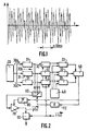
- This frequency which varies from 70 to 150 hertz approximately for men and from 150 to 400 hertz approximately for women, characterizes so-called voiced sounds (an example of representation of the amplitude A of a voiced sound as a function of time t is given in Figure 1).
- the air flow then excites in forced oscillations of the cavities of the vocal tract, to the shape of which correspond natural frequencies F 1 , F 2 , F 3 , etc ... called formants.
- the voice signal also includes signals which do not have the coherence of voiced sounds, but which are similar to noise, emitted by a source without natural frequency, and which do not excite the natural frequencies of the vocal tract. (these sounds are linked to the production of most consonants).
- the characteristics of the voice signal can be highlighted by a spectral analysis, which shows that the emitted spectrum comprises on the one hand a spectrum of lines (periodic excitations) for the production of the voiced sounds and on the other hand a continuous spectrum (excitations inconsistent) for producing unvoiced sounds.
- voice signal shows in that its processing with a view to a faithful transmission of the bandwidth it represents leads to manipulate at the level acoustics a considerable data flow. Analysis techniques speech were then developed to reduce considerably this data flow. By eliminating redundancies thus obtained, the voice signal, initially of the type analog, can then after digitization be compressed to bit rates which, due to the compression ratio achieved, allow its transport on current very low speed lines.
- This coder is based on a principle called analysis by synthesis (in English: linear prediction analysis-by-synthesis coding), which comprises on the one hand an analysis step, to determine the coefficients of the synthesis filter, and on the other hand, a step of analysis by synthesis, which consists in finding or calculating a sequence of excitations minimizing a determined error criterion (we often use the criterion of least squares).
- analysis by synthesis in English: linear prediction analysis-by-synthesis coding
- coding mentioned in the draft standard cited known as linear predictive coding excited by codes (in English, C ode E xcited L inear P redictive encoding, or CELP coding, term which we will adopt in the following description), s is based on a simplified model of the speech production mode, according to which, as a first approximation, the voice signal can be modeled by a short-term (voice path) and long-term (voice source) correlation filter having as input an excitation signal.
- LPC linear prediction filtering
- a (z) 10 in the case of recommendation G.723
- LTP long-term analysis
- the short-term analysis is based on a predictive method in which the basic idea implemented is, knowing an input voice signal or observed signal s (n) (the index n denotes the rank of the sample) , to find a filter which, excited by an excitation signal x (n), will deliver a predicted signal p (n) as close as possible to s (n) and which therefore allows, by difference between s (n) and p (n), to obtain a residual error e (n) as small as possible.
- the speech coder described in the document G.723 cited above receives a signal consisting of blocks, or frames, comprising 240 samples, with a sampling frequency of 8 kHz, and each frame is assumed to be divided into four subframes of 60 samples each.
- a filter 1 / A (z) called synthesis filter, which, applied to an excitation signal x (n), allows to obtain a signal p (n) as close as possible to the sampling signal s (n), it is equivalent to searching for a filter A (z), said to be of analysis, whose coefficients are such that the filter output signal is the most bleached possible when this filter is attacked by the signal to transmit (in an ideal encoder, the output signal would be a real white noise).
- the voice signal it then, to be able to reconstitute it later, transmit the coefficients of the filter A (z) (these coefficients are less consuming coding bits than would be the case transmission of the prediction error or of
- the first performs a decorrelation of adjacent samples: its purpose is to define the coefficients of the input filter most suitable for obtaining after filtering the signal known, of a residual signal as close as possible to white noise.
- t (.) And p (.) Denote respectively, the sample concerned in the signal to be modeled and the predicted sample, ⁇ is a gain value, and OLP (in English, O pen L oop P itch) designates the quantity called open-loop voicing period, characteristic of the periodicity of the signal.
- OLP in English, O pen L oop P itch
- the determination of the OLP period and that of the gain ⁇ suffices to implement the prediction represented by expression (3).
- this determination has the form of a direct dependence: to within a gain factor, the sample to be predicted would be equal to one of the samples already occurring.
- the first component of the first vector of each V-vector is obtained by shifting from (OLP-2 + ⁇ ) in the past, knowing that ⁇ can take the values (-1, 0, 1) for the even subframes and (-1, 0, 1, 2) for odd subframes.
- the other four vectors of each V-vector are obtained using the first vector by successive shifts of a sample in the direction of increasing times.
- the operation corresponding to expression (4) is therefore a prediction with linear combination of samples, during which the search for the solution vector is refined by varying the gain ⁇ , for example, in the case of the G project. 723 cited, giving it five distinct values ( ⁇ is the gain vector formed by these five values), and also by adjusting the OLP quantity by a small value ⁇ .
- the selection, during this research, of the best possible solution vector is made by including in the course of the determination process a step of minimization, in the least squares sense, of the difference between the vector t (n) output from the analysis filter (the coefficients of which will be transmitted) and the solution vectors resulting from the implementation of expression (4).
- the analysis filter which, having received the voice signal to be transmitted, only delivers a residual signal constituting the periodicity information of this initial voice signal, it is this signal depleted t (n) for which the prediction explained below will be implemented with reference to FIG. 2.
- the adaptive dictionary therefore contains the excitation vectors candidates for the construction of an approximation of this vector t (not).
- FIG. 2 shows, in the case of the G.723 project. an example of a prediction device making it possible to implement the principles of determination which have just been described.
- This device firstly comprises a circuit 20 for storing excitation vectors (this is the adaptive dictionary mentioned above), constructed from the optimal excitation of the preceding sub-frame, that is to say -to say excitations selected during a previous implementation of the same prediction method for previous samples.
- excitation vectors this is the adaptive dictionary mentioned above
- OLP + ⁇ CLP (in English, C losed L oop P itch)
- circuit 20 is followed, in the case where one is in an even subframe and where ⁇ takes for example the three values - 1, 0 and + 1 (this is the case shown in FIG. 2), of channels 30, here three identical channels 30a, 30b, 30c (circuit 20 is followed by four identical channels, referenced so similar, in the case where one is in an odd sub-frame, ⁇ then taking the four values - 1, 0, + 1, + 2).
- Each of these channels processes the V-vector of the adaptive dictionary which corresponds to the step ⁇ of the channel considered, and includes in this firstly in series effect a filter 31, having as response the impulse response of the synthesis filter (defined above).
- a circuit 32 also receiving the target vector to be modeled t (n) is then provided for the calculation of a vector with twenty components V ( ⁇ ) consisting of five correlation terms between the filtered vectors and the residual vector (in English: cross-products), given by the scalar products of the five filtered vectors of the adaptive dictionary by the target vector t (n), five energy terms, given by the scalar products of the five filtered vectors of the adaptive dictionary by themselves, and ten two-by-two correlation terms between the filtered vectors. From these correlations, it is possible to determine to what extent the residual vector or target vector t (n) can be modeled from V-vectors of the adaptive dictionary.
- the gains which are quantized, are provided by a memory 40, or quantization table, which contains the possible values for the various gains (170 to 5.3 kbits / s., And 85 or 170 to 6.3 kbits / s ., the 170 vectors of the table used in one or the other case then being the same).
- the information relating to the gains is given, in this quantification table, in the form of vectors each having twenty terms (as previously) defined as follows: five gain values, five values equal to the square of these gains, ten values corresponding to the ten two by two of these five gain values.
- the gain vector ⁇ optimal in the sense of expression (5) is the one which cancels the derivative of ⁇ with respect to each of the components of the vector, and which, by this very fact, maximizes the scalar product of V ( ⁇ ) by a vector from the quantification table.
- a circuit 50 then allows the selection of the maximum scalar product among the three or four scalar products available at the output of these three (or four) circuits, maximum scalar product to which an optimal value of the step correspondent (stored in a memory 110) and an optimal value of the gain vector ⁇ .
- the optimal value of ⁇ is of course one of the three (or four) values used in the three (or four) channels, and the value thus selected makes it possible to control a switch 60, comprising as many inputs as there are of tracks (three, or four).
- This switch provided at the output of the filters 31, makes it possible to select the filtered V-vector constituting the best representative for the desired solution vector.
- This selected filtered vector is then presented at the input of an amplifier 70 whose gain vector ⁇ , delivered by the selection circuit 50, had been stored in a memory 80 present at the output of this circuit 50.
- the optimal filtered V-vector thus amplified is the prediction vector p (n) sent to the negative terminal of a subtractor 90 which receives on its positive terminal the vector t (n) output from the CELP encoder analysis filter.
- a first object of the invention is therefore to propose a simpler prediction method, with almost equal quality, than the one previously described.
- Another object of the invention is to propose a coder for speech similar to that just described, but with a reduced complexity and while maintaining quality practically equivalent.
- the solution according to the invention makes it possible to make a much lower number of paths (four in the case of the coder according to this document), with an almost imperceptible deterioration in quality.
- the basic idea of the structure thus proposed is indeed the following: by making the simplifying assumption that the predictors are decorrelated, or, which is equivalent, that the correlations between filtered vectors taken two by two, previously defined, are zero, we can, for each sub-frame and for each channel corresponding to a step ⁇ , define an initial gain vector ⁇ ( ⁇ ) init , without costly matrix inversion calculation. The components of this vector are then, for the channel considered, the successive ratios of the correlation terms between the filtered vectors and the target vector and the energy terms of the vector V ( ⁇ ) defined previously.
- the optimal initial step determined for each subframe by the calculation subset provided at the output of ways, is then the one that maximizes one of the three, or four depending on whether the subframe is even or odd, scalar products of ⁇ T ( ⁇ ) init by V ( ⁇ ), determined by the calculation circuit provided for in each channel after the calculation of V ( ⁇ ) (we recall here that V ( ⁇ ) was defined previously, while ⁇ T ( ⁇ ) init is a vector that has the same number of components as V ( ⁇ ), namely, in this case: the five components of the
- the vector of the optimal gain for each subframe is then obtained using the circuit provided at the output of the quantification table and which performs the search for the maximum value of the scalar product of the vector.
- V ( ⁇ ) corresponding to the optimal value of the step ⁇ which has just been calculated by each of the vectors (here 170 or 85 depending on the flow) of said table.
- This determination of the optimal gain vector requires only one scan of the quantization table per subframe, ie four per frame (instead of three or four per subframe depending on whether the subframe is even or odd. , or fourteen per frame), which results in a significant reduction in complexity.
- the prediction device such as shown in Figure 3, present with that of Figure 2 of common elements, namely the circuit 20 for memorizing the candidate excitation vectors (or adaptive dictionary), filters 31, the circuits 32 for calculating the correlation terms and of energy, memory 40 (or quantization table), switch 60, amplifier 70, memory 80, subtractor 90, and memory 110.
- the search for the optimal gain vector is then carried out by the selection circuit 150, and the vector thus selected is kept in memory 80.
- the switch 60 provided at the output of the filters 31 and whose position is controlled by the value of ⁇ issue from memory 110, sends the selected filtered V-vector to amplifier 70.
- the optimal filtered V-vector thus amplified is the prediction vector p (n), sent, as in the case of FIG. 2, to the subtractor 90.
Landscapes
- Engineering & Computer Science (AREA)
- Computational Linguistics (AREA)
- Signal Processing (AREA)
- Health & Medical Sciences (AREA)
- Audiology, Speech & Language Pathology (AREA)
- Human Computer Interaction (AREA)
- Physics & Mathematics (AREA)
- Acoustics & Sound (AREA)
- Multimedia (AREA)
- Compression, Expansion, Code Conversion, And Decoders (AREA)
Priority Applications (1)
| Application Number | Priority Date | Filing Date | Title |
|---|---|---|---|
| EP96934902A EP0796490B1 (fr) | 1995-10-11 | 1996-10-11 | Methode et dispositif de prediction de signal pour un codeur de parole |
Applications Claiming Priority (6)
| Application Number | Priority Date | Filing Date | Title |
|---|---|---|---|
| FR9511937 | 1995-10-11 | ||
| FR9511937A FR2739964A1 (fr) | 1995-10-11 | 1995-10-11 | Dispositif de prediction de periode de voisement pour codeur de parole |
| EP96402030 | 1996-09-25 | ||
| EP96402030 | 1996-09-25 | ||
| PCT/FR1996/001596 WO1997014139A1 (fr) | 1995-10-11 | 1996-10-11 | Methode et dispositif de prediction de signal pour un codeur de parole |
| EP96934902A EP0796490B1 (fr) | 1995-10-11 | 1996-10-11 | Methode et dispositif de prediction de signal pour un codeur de parole |
Publications (2)
| Publication Number | Publication Date |
|---|---|
| EP0796490A1 EP0796490A1 (fr) | 1997-09-24 |
| EP0796490B1 true EP0796490B1 (fr) | 2000-08-02 |
Family
ID=26144072
Family Applications (1)
| Application Number | Title | Priority Date | Filing Date |
|---|---|---|---|
| EP96934902A Expired - Lifetime EP0796490B1 (fr) | 1995-10-11 | 1996-10-11 | Methode et dispositif de prediction de signal pour un codeur de parole |
Country Status (4)
| Country | Link |
|---|---|
| EP (1) | EP0796490B1 (ja) |
| JP (1) | JPH11500837A (ja) |
| DE (1) | DE69609592T2 (ja) |
| WO (1) | WO1997014139A1 (ja) |
Families Citing this family (1)
| Publication number | Priority date | Publication date | Assignee | Title |
|---|---|---|---|---|
| JP3263347B2 (ja) * | 1997-09-20 | 2002-03-04 | 松下電送システム株式会社 | 音声符号化装置及び音声符号化におけるピッチ予測方法 |
Family Cites Families (2)
| Publication number | Priority date | Publication date | Assignee | Title |
|---|---|---|---|---|
| US4899385A (en) * | 1987-06-26 | 1990-02-06 | American Telephone And Telegraph Company | Code excited linear predictive vocoder |
| US5138661A (en) * | 1990-11-13 | 1992-08-11 | General Electric Company | Linear predictive codeword excited speech synthesizer |
-
1996
- 1996-10-11 EP EP96934902A patent/EP0796490B1/fr not_active Expired - Lifetime
- 1996-10-11 WO PCT/FR1996/001596 patent/WO1997014139A1/fr active IP Right Grant
- 1996-10-11 DE DE69609592T patent/DE69609592T2/de not_active Expired - Fee Related
- 1996-10-11 JP JP9514782A patent/JPH11500837A/ja active Pending
Also Published As
| Publication number | Publication date |
|---|---|
| WO1997014139A1 (fr) | 1997-04-17 |
| DE69609592T2 (de) | 2001-03-29 |
| JPH11500837A (ja) | 1999-01-19 |
| EP0796490A1 (fr) | 1997-09-24 |
| DE69609592D1 (de) | 2000-09-07 |
Similar Documents
| Publication | Publication Date | Title |
|---|---|---|
| EP0749626B1 (fr) | Procede de codage de parole a prediction lineaire et excitation par codes algebriques | |
| EP0768770B1 (fr) | Procédé et dispositif de création d'un bruit de confort dans un système de transmission numérique de parole | |
| FR2742568A1 (fr) | Procede d'analyse par prediction lineaire d'un signal audiofrequence, et procedes de codage et de decodage d'un signal audiofrequence en comportant application | |
| EP0608174B1 (fr) | Systeme de codage-décodage prédictif d'un signal numérique de parole par transformée adaptative à codes imbriqués | |
| FR2731548A1 (fr) | Recherche profondeur d'abord dans un repertoire algebrique pour un encodage rapide de la paroie | |
| FR2522179A1 (fr) | Procede et appareil de reconnaissance de paroles permettant de reconnaitre des phonemes particuliers du signal vocal quelle que soit la personne qui parle | |
| EP0428445B1 (fr) | Procédé et dispositif de codage de filtres prédicteurs de vocodeurs très bas débit | |
| WO2005066938A1 (fr) | Procede de codage multiple optimise | |
| EP0481895B1 (fr) | Procédé de transmission, à bas débit, par codage CELP d'un signal de parole et système correspondant | |
| WO2018146305A1 (fr) | Methode et appareil de modification dynamique du timbre de la voix par decalage en fréquence des formants d'une enveloppe spectrale | |
| JPH06214599A (ja) | コードブック励起直線予測探索ループにおいて使用するための適応ピッチパルス強調装置および方法 | |
| JP3357795B2 (ja) | 音声符号化方法および装置 | |
| EP1836699B1 (fr) | Procédé et dispositif de codage audio optimisé entre deux modèles de prediction à long terme | |
| EP0685833A1 (fr) | Procédé de codage de parole à prédiction linéaire | |
| EP0796490B1 (fr) | Methode et dispositif de prediction de signal pour un codeur de parole | |
| FR2653557A1 (fr) | Appareil et procede pour le traitement de la parole. | |
| EP0616315A1 (fr) | Dispositif de codage et de décodage numérique de la parole, procédé d'exploration d'un dictionnaire pseudo-logarithmique de délais LTP, et procédé d'analyse LTP | |
| EP0573358B1 (fr) | Procédé et dispositif de synthèse vocale à vitesse variable | |
| JP3462464B2 (ja) | 音声符号化方法、音声復号化方法及び電子装置 | |
| EP2589045B1 (fr) | Codage/décodage prédictif linéaire adaptatif | |
| WO2011144863A1 (fr) | Codage avec mise en forme du bruit dans un codeur hierarchique | |
| EP1192619B1 (fr) | Codage et decodage audio par interpolation | |
| EP1605440A1 (fr) | Procédé de séparation de signaux sources à partir d'un signal issu du mélange | |
| FR2760285A1 (fr) | Procede et dispositif de generation d'un signal de bruit pour la sortie non vocale d'un signal decode de la parole | |
| EP0454552A2 (fr) | ProcédÀ© et dispositif de codage bas débit de la parole |
Legal Events
| Date | Code | Title | Description |
|---|---|---|---|
| PUAI | Public reference made under article 153(3) epc to a published international application that has entered the european phase |
Free format text: ORIGINAL CODE: 0009012 |
|
| AK | Designated contracting states |
Kind code of ref document: A1 Designated state(s): DE FR GB |
|
| 17P | Request for examination filed |
Effective date: 19971017 |
|
| GRAG | Despatch of communication of intention to grant |
Free format text: ORIGINAL CODE: EPIDOS AGRA |
|
| 17Q | First examination report despatched |
Effective date: 19990921 |
|
| GRAG | Despatch of communication of intention to grant |
Free format text: ORIGINAL CODE: EPIDOS AGRA |
|
| GRAH | Despatch of communication of intention to grant a patent |
Free format text: ORIGINAL CODE: EPIDOS IGRA |
|
| RIC1 | Information provided on ipc code assigned before grant |
Free format text: 7G 10L 19/08 A |
|
| GRAH | Despatch of communication of intention to grant a patent |
Free format text: ORIGINAL CODE: EPIDOS IGRA |
|
| GRAA | (expected) grant |
Free format text: ORIGINAL CODE: 0009210 |
|
| AK | Designated contracting states |
Kind code of ref document: B1 Designated state(s): DE FR GB |
|
| REF | Corresponds to: |
Ref document number: 69609592 Country of ref document: DE Date of ref document: 20000907 |
|
| GBT | Gb: translation of ep patent filed (gb section 77(6)(a)/1977) |
Effective date: 20000928 |
|
| PGFP | Annual fee paid to national office [announced via postgrant information from national office to epo] |
Ref country code: DE Payment date: 20001220 Year of fee payment: 5 |
|
| PLBE | No opposition filed within time limit |
Free format text: ORIGINAL CODE: 0009261 |
|
| STAA | Information on the status of an ep patent application or granted ep patent |
Free format text: STATUS: NO OPPOSITION FILED WITHIN TIME LIMIT |
|
| 26N | No opposition filed | ||
| PGFP | Annual fee paid to national office [announced via postgrant information from national office to epo] |
Ref country code: FR Payment date: 20011026 Year of fee payment: 6 |
|
| PGFP | Annual fee paid to national office [announced via postgrant information from national office to epo] |
Ref country code: GB Payment date: 20011031 Year of fee payment: 6 |
|
| REG | Reference to a national code |
Ref country code: GB Ref legal event code: IF02 |
|
| PG25 | Lapsed in a contracting state [announced via postgrant information from national office to epo] |
Ref country code: DE Free format text: LAPSE BECAUSE OF NON-PAYMENT OF DUE FEES Effective date: 20020702 |
|
| PG25 | Lapsed in a contracting state [announced via postgrant information from national office to epo] |
Ref country code: GB Free format text: LAPSE BECAUSE OF NON-PAYMENT OF DUE FEES Effective date: 20021011 |
|
| GBPC | Gb: european patent ceased through non-payment of renewal fee |
Effective date: 20021011 |
|
| PG25 | Lapsed in a contracting state [announced via postgrant information from national office to epo] |
Ref country code: FR Free format text: LAPSE BECAUSE OF NON-PAYMENT OF DUE FEES Effective date: 20030630 |
|
| REG | Reference to a national code |
Ref country code: FR Ref legal event code: ST |