EP0795681A1 - Actuation mechanism for variable inlet vanes in turbomachine compressor - Google Patents
Actuation mechanism for variable inlet vanes in turbomachine compressor Download PDFInfo
- Publication number
- EP0795681A1 EP0795681A1 EP97400549A EP97400549A EP0795681A1 EP 0795681 A1 EP0795681 A1 EP 0795681A1 EP 97400549 A EP97400549 A EP 97400549A EP 97400549 A EP97400549 A EP 97400549A EP 0795681 A1 EP0795681 A1 EP 0795681A1
- Authority
- EP
- European Patent Office
- Prior art keywords
- platform
- pivot
- manifold
- hollow
- control device
- Prior art date
- Legal status (The legal status is an assumption and is not a legal conclusion. Google has not performed a legal analysis and makes no representation as to the accuracy of the status listed.)
- Granted
Links
Images


Classifications
-
- F—MECHANICAL ENGINEERING; LIGHTING; HEATING; WEAPONS; BLASTING
- F01—MACHINES OR ENGINES IN GENERAL; ENGINE PLANTS IN GENERAL; STEAM ENGINES
- F01D—NON-POSITIVE DISPLACEMENT MACHINES OR ENGINES, e.g. STEAM TURBINES
- F01D17/00—Regulating or controlling by varying flow
- F01D17/10—Final actuators
- F01D17/12—Final actuators arranged in stator parts
- F01D17/14—Final actuators arranged in stator parts varying effective cross-sectional area of nozzles or guide conduits
- F01D17/16—Final actuators arranged in stator parts varying effective cross-sectional area of nozzles or guide conduits by means of nozzle vanes
- F01D17/162—Final actuators arranged in stator parts varying effective cross-sectional area of nozzles or guide conduits by means of nozzle vanes for axial flow, i.e. the vanes turning around axes which are essentially perpendicular to the rotor centre line
-
- F—MECHANICAL ENGINEERING; LIGHTING; HEATING; WEAPONS; BLASTING
- F04—POSITIVE - DISPLACEMENT MACHINES FOR LIQUIDS; PUMPS FOR LIQUIDS OR ELASTIC FLUIDS
- F04D—NON-POSITIVE-DISPLACEMENT PUMPS
- F04D29/00—Details, component parts, or accessories
- F04D29/40—Casings; Connections of working fluid
- F04D29/52—Casings; Connections of working fluid for axial pumps
- F04D29/54—Fluid-guiding means, e.g. diffusers
- F04D29/56—Fluid-guiding means, e.g. diffusers adjustable
- F04D29/563—Fluid-guiding means, e.g. diffusers adjustable specially adapted for elastic fluid pumps
-
- F—MECHANICAL ENGINEERING; LIGHTING; HEATING; WEAPONS; BLASTING
- F05—INDEXING SCHEMES RELATING TO ENGINES OR PUMPS IN VARIOUS SUBCLASSES OF CLASSES F01-F04
- F05D—INDEXING SCHEME FOR ASPECTS RELATING TO NON-POSITIVE-DISPLACEMENT MACHINES OR ENGINES, GAS-TURBINES OR JET-PROPULSION PLANTS
- F05D2230/00—Manufacture
- F05D2230/60—Assembly methods
-
- F—MECHANICAL ENGINEERING; LIGHTING; HEATING; WEAPONS; BLASTING
- F05—INDEXING SCHEMES RELATING TO ENGINES OR PUMPS IN VARIOUS SUBCLASSES OF CLASSES F01-F04
- F05D—INDEXING SCHEME FOR ASPECTS RELATING TO NON-POSITIVE-DISPLACEMENT MACHINES OR ENGINES, GAS-TURBINES OR JET-PROPULSION PLANTS
- F05D2240/00—Components
- F05D2240/60—Shafts
- F05D2240/61—Hollow
-
- F—MECHANICAL ENGINEERING; LIGHTING; HEATING; WEAPONS; BLASTING
- F05—INDEXING SCHEMES RELATING TO ENGINES OR PUMPS IN VARIOUS SUBCLASSES OF CLASSES F01-F04
- F05D—INDEXING SCHEME FOR ASPECTS RELATING TO NON-POSITIVE-DISPLACEMENT MACHINES OR ENGINES, GAS-TURBINES OR JET-PROPULSION PLANTS
- F05D2260/00—Function
- F05D2260/20—Heat transfer, e.g. cooling
-
- F—MECHANICAL ENGINEERING; LIGHTING; HEATING; WEAPONS; BLASTING
- F05—INDEXING SCHEMES RELATING TO ENGINES OR PUMPS IN VARIOUS SUBCLASSES OF CLASSES F01-F04
- F05D—INDEXING SCHEME FOR ASPECTS RELATING TO NON-POSITIVE-DISPLACEMENT MACHINES OR ENGINES, GAS-TURBINES OR JET-PROPULSION PLANTS
- F05D2260/00—Function
- F05D2260/50—Kinematic linkage, i.e. transmission of position
-
- F—MECHANICAL ENGINEERING; LIGHTING; HEATING; WEAPONS; BLASTING
- F05—INDEXING SCHEMES RELATING TO ENGINES OR PUMPS IN VARIOUS SUBCLASSES OF CLASSES F01-F04
- F05D—INDEXING SCHEME FOR ASPECTS RELATING TO NON-POSITIVE-DISPLACEMENT MACHINES OR ENGINES, GAS-TURBINES OR JET-PROPULSION PLANTS
- F05D2260/00—Function
- F05D2260/70—Adjusting of angle of incidence or attack of rotating blades
- F05D2260/74—Adjusting of angle of incidence or attack of rotating blades by turning around an axis perpendicular the rotor centre line
Definitions
- the invention relates to a pivot control device integrated in a manifold. It applies in particular in the field of aeronautics, to turbomachinery comprising an air intake guide vane with variable pitch vanes.
- Some turbomachines have variable-pitch guide vanes that regulate the air flow supplying the compressor stages located downstream.
- the blades have pivots which extend through an envelope delimiting a flow vein.
- Each pivot is driven in rotation by means of a link connected to a control mechanism such as a ring whose movement causes all the links to tilt in unison.
- the object of the invention is to solve this problem and to produce a control device for a pivot integrated in a manifold allowing the defrosting of the moving blades and simultaneously ensuring the orientation of the moving blades.
- the control device comprises means for fixing and articulation of the pivot mounted in a bore of a platform fixed to the manifold by upstream flanges and downstream.
- the pivot fixing and articulation means comprise a hollow friction sleeve provided with a circumferential slot in which is inserted an upstream part of a link.
- Means for controlling the orientation of the movable blades are mounted outside the manifold and connected to a downstream part of the link.
- Corresponding lights are arranged in the manifold and in the platform so as to ensure the maneuverability of the variable-timing control device by means of the link.
- the upstream part of the rod is inserted into the bore of the platform by the lights of the manifold and of the platform and comprises an eye in which the hollow pivot is inserted.
- the lights of the collector and of the platform are arranged opposite the slot of the hollow socket.
- downstream part of the link is arranged outside the manifold and connected on the one hand to the upstream part of the link and on the other hand to the means for controlling the orientation of the movable blades.
- Defrosting of the movable blade is ensured by means of the hollow pivot which allows the circulation of hot air between the manifold and the interior of the blades.
- the flange-to-flange fastenings between the manifold and the platform provide sealing between the interior and exterior of the manifold.
- the control device for a pivot integrated in an air manifold in which the pivot of a movable blade with variable setting is driven in rotation by means of a connecting rod connected to means for controlling the orientation of the movable blade and comprising means for fixing and pivot articulation mounted in a bore of a platform fixed to the air collector by upstream and downstream flanges is characterized in that the fixing means and pivot articulation comprise a hollow friction sleeve fixed in the bore of the platform, the hollow socket having a circumferential slot in which is inserted an upstream part of the link.
- the air intake of the turbojet engine is provided with fixed arms 1 and guide vanes 2 movable around a radial axis XX 'passing through pivots 3 located at the upper ends movable blades 2.
- the fixed arms 1, the movable vanes 2 and the pivots 3 are hollow so as to allow the circulation of the hot defrost air taken at the outlet of the high pressure compressor not shown.
- the fixed arms 1 and the pivots 3 of the movable vanes 2 are mounted in external platforms 4 brought into contact with one another, and are capped by an air manifold 5 secured to an external ferrule 6.
- the platforms 4 comprise two upstream 7 and downstream 8 side flanges which are fixed to corresponding flanges of the manifold 5 for example by means of a screw and nut system.
- the platforms 4 form with the manifold 5 a toroidal enclosure which receives, contains and distributes the deicing air from the fixed arms 1 and the movable vanes 2.
- the seal between the inside and the outside of the manifold is ensured by the flange against flange fixings between the manifold 5 and the platforms 4.
- Each platform 4 has on its external face, between the two lateral flanges 7,8, a thick transverse region traversed by two bores 9, 10 , respectively upstream and downstream oriented radially.
- the fixed arms 1 are embedded and bolted in the first upstream bore 9 of the thickened region of the platform 4.
- the pivots 3 of the movable blades 2 are mounted in the second downstream bore 10 and pivot in this second bore via a hollow friction sleeve 11 secured to the platform 4.
- the pivoting of the pivots 3 of the movable vanes 2 around the radial axis XX ' is controlled by a rod made up of two parts respectively upstream 12 and downstream 13.
- the upstream parts 12 and downstream 13 are respectively arranged inside and outside the manifold 5.
- the upstream portion 12 is inserted into the bore 10 of the platform 4 by means of lights made respectively in the manifold 5, in the platform 4 and in the hollow friction sleeve 11, the different lights being arranged opposite one another.
- the downstream part 13 is connected by a first end to the upstream part 12 by means of a locking lock nut 14 and comprises a second end movable linearly in a ball joint 15 secured to a control and synchronization ring 16
- the control of the pivoting of all the movable blades is carried out simultaneously via the control ring in a manner known per se.
- FIG. 2 represents a perspective and exploded view of the means of fixing and articulation of the pivots of the movable blades, according to the invention.
- the articulation of the pivot 3 of a movable blade 2 inside the downstream bore 10 of the platform 4 is effected by means of a hollow friction sleeve 11.
- the hollow sleeve comprises, in its upper region, a slit 20 circumferential of predetermined width.
- the hollow socket 11 is put in place and fixed in the downstream bore 10 of the platform 4 so that the slot 20 is disposed opposite the light 21 of the platform 4.
- the upstream part 12 of the link has a flat area pierced at its end with an eye 22 of predetermined shape and section, for example in the shape of a square. This flat area is inserted into the downstream bore 10 of the platform 4 via the lumen 21 of the platform and the slot 20 of the hollow bushing 11.
- a hollow tip 17 is permanently fixed, for example by shrinking, on the pivot 3 of the movable blade 2.
- the tip 17 has a threaded upper part 18, an intermediate part 19 of predetermined shape and section, and a lower part in which the pivot 3 is fitted.
- the shape of the intermediate part 19 is complementary to the shape of the eye 22 of the upstream part 12 of the link and its section is slightly smaller than that of the eye 22 so that when the pivot 3 provided with its end piece 17 is put in place in the bore 10 of the platform 4, the intermediate part 19 fits into the eye 22 of the link 12, the eye 22 fitting exactly the shape of the intermediate part 19 of the end piece 17.
- the pivot 3 of the moving blade 2 and the upstream part 12 of the link are made integral in rotation by a tightening means, for example a shouldered nut 23 screwed onto the threaded upper part 18 of the end piece 17.
- the orientation of the blades In order for the orientation of the blades to be carried out with precision, it is necessary for the orientation of the intermediate part 19 of the end piece 17 to be carried out precisely relative to the movable blade 2. Likewise, the slot 20 of the socket 11 must be oriented very precisely with respect to the platform 4. For this purpose, it is preferable to use a mounting tool or a polarizing device.
- the platform 4 When the pivot 2 provided with its end piece 17 is mounted in the platform 4 with the friction sleeve 11, the upstream part 12 of the connecting rod and the tightening nut 23, the platform 4 is put in place in the manifold 5 and the upstream side 7 and downstream 8 side flanges are fixed to corresponding flanges of the manifold 5.
- the side flanges 7, 8 have several holes 24 in which are inserted in known manner fixing means not shown.
- holes 25 are provided for fixing the different platforms to one another.
- the downstream part 13 of the link disposed outside the manifold 5 is then fixed by a first end to the upstream part 12, for example by screwing then tightening by means of a lock nut 14.
- the downstream part 13 of the link comprises a second end, for example of square section, linked to means, not shown in FIG. 2, for controlling and synchronizing the pivoting of the blades by means of the ball joint 15 secured to the control ring 16.
- Figure 3 is a perspective view of the means of fixing and articulation of the pivots of the movable blades after mounting in the platform, according to the invention.
- the pivots 3 of the blades, the bush 11 and the clamping nut 23 are all hollow, they allow the arrival of the hot defrost air inside the movable blades.
- the slot 20 of the socket 11 and the light 21 of the platform 4 allow the maneuverability of the device variable pitch control of the vanes which is located outside the manifold 5.
Abstract
Description
L'invention concerne un dispositif de commande pour pivot intégré dans un collecteur. Elle s'applique en particulier dans le domaine de l'aéronautique, aux turbomachines comportant un aubage directeur d'entrée d'air à aubes à calage variable.The invention relates to a pivot control device integrated in a manifold. It applies in particular in the field of aeronautics, to turbomachinery comprising an air intake guide vane with variable pitch vanes.
Certaines turbomachines comportent des aubes directrices à calage variable permettant de régulariser le flux d'air alimentant les étages des compresseurs situés en aval.
Les aubes comportent des pivots qui s'étendent à travers une enveloppe délimitant une veine d'écoulement.
Chaque pivot est entraîné en rotation par l'intermédiaire d'une biellette reliée à un mécanisme de commande tel qu'un anneau dont le déplacement fait basculer toutes les biellettes à l'unisson.Some turbomachines have variable-pitch guide vanes that regulate the air flow supplying the compressor stages located downstream.
The blades have pivots which extend through an envelope delimiting a flow vein.
Each pivot is driven in rotation by means of a link connected to a control mechanism such as a ring whose movement causes all the links to tilt in unison.
Pour éliminer le givre susceptible de se former à la surface des aubes mobiles, il est connu de prélever de l'air chaud dans le compresseur haute pression, de l'amener jusqu'à un collecteur d'air, puis d'injecter et de faire circuler cet air à l'intérieur des aubes, l'air étant injecté, par exemple, par l'intermédiaire des pivots.To remove the frost likely to form on the surface of the moving blades, it is known to take hot air from the high pressure compressor, to bring it to an air manifold, then to inject and circulate this air inside the blades, the air being injected, for example, via the pivots.
Cependant, l'espace disponible entre le carter du moteur et les extrémités des aubes est généralement réduit et il est souvent difficile, voire impossible de loger dans cet espace, un dispositif de commande d'orientation des aubes et un dispositif de dégivrage des aubes mobiles.However, the space available between the motor housing and the ends of the blades is generally reduced and it is often difficult, if not impossible, to accommodate in this space, a device for controlling the orientation of the blades and a device for defrosting the moving blades. .
le but de l'invention est de résoudre ce problème et de réaliser un dispositif de commande pour pivot intégré dans un collecteur permettant le dégivrage des aubes mobiles et assurant simultanément l'orientation des aubes mobiles. Pour cela, le dispositif de commande comporte des moyens de fixation et d'articulation du pivot montés dans un alésage d'une plate-forme fixée au collecteur par des brides amont et aval. Les moyens de fixation et d'articulation du pivot comportent une douille creuse de frottement munie d'une fente circonférentielle dans laquelle est insérée une partie amont d'une biellette. Des moyens de commande de l'orientation des aubes mobiles sont montés a l'extérieur du collecteur et reliés à une partie aval de la biellette. Des lumières correspondantes sont aménagées dans le collecteur et dans la plate-forme de façon à assurer la manoeuvrabilité du dispositif de commande à calage variable par l'intermédiaire de la biellette. La partie amont de la biellette est insérée dans l'alésage de la plate-forme par les lumières du collecteur et de la plate-forme et comporte un oeil dans lequel est inséré le pivot creux. Les lumières du collecteur et de la plate-forme sont disposées en regard de la fente de la douille creuse.the object of the invention is to solve this problem and to produce a control device for a pivot integrated in a manifold allowing the defrosting of the moving blades and simultaneously ensuring the orientation of the moving blades. For this, the control device comprises means for fixing and articulation of the pivot mounted in a bore of a platform fixed to the manifold by upstream flanges and downstream. The pivot fixing and articulation means comprise a hollow friction sleeve provided with a circumferential slot in which is inserted an upstream part of a link. Means for controlling the orientation of the movable blades are mounted outside the manifold and connected to a downstream part of the link. Corresponding lights are arranged in the manifold and in the platform so as to ensure the maneuverability of the variable-timing control device by means of the link. The upstream part of the rod is inserted into the bore of the platform by the lights of the manifold and of the platform and comprises an eye in which the hollow pivot is inserted. The lights of the collector and of the platform are arranged opposite the slot of the hollow socket.
la partie aval de la biellette est disposée à l'extérieur du collecteur et reliée d'une part à la partie amont de la biellette et d'autre part aux moyens de commande de l'orientation des aubes mobiles.the downstream part of the link is arranged outside the manifold and connected on the one hand to the upstream part of the link and on the other hand to the means for controlling the orientation of the movable blades.
Le dégivrage de l'aube mobile est assuré par l'intermédiaire du pivot creux qui permet la circulation de l'air chaud entre le collecteur et l'intérieur des aubes.Defrosting of the movable blade is ensured by means of the hollow pivot which allows the circulation of hot air between the manifold and the interior of the blades.
Les fixations bride contre bride entre le collecteur et la plate-forme assurent l'étanchéité entre l'intérieur et l'extérieur du collecteur.The flange-to-flange fastenings between the manifold and the platform provide sealing between the interior and exterior of the manifold.
Selon l'invention le dispositif de commande pour pivot intégré dans un collecteur d'air dans lequel le pivot d'une aube mobile à calage variable est entraîné en rotation par l'intermédiaire d'une biellette reliée à des moyens de commande de l'orientation de l'aube mobile et comportant des moyens de fixation et d'articulation du pivot montés dans un alésage d'une plate-forme fixée au collecteur d'air par des brides amont et aval est caractérisé en ce que les moyens de fixation et d'articulation du pivot comportent une douille creuse de frottement fixée dans l'alésage de la plate-forme, la douille creuse comportant une fente circonférentielle dans laquelle est insérée une partie amont de la biellette.According to the invention, the control device for a pivot integrated in an air manifold in which the pivot of a movable blade with variable setting is driven in rotation by means of a connecting rod connected to means for controlling the orientation of the movable blade and comprising means for fixing and pivot articulation mounted in a bore of a platform fixed to the air collector by upstream and downstream flanges is characterized in that the fixing means and pivot articulation comprise a hollow friction sleeve fixed in the bore of the platform, the hollow socket having a circumferential slot in which is inserted an upstream part of the link.
D'autres particularités et avantages de l'invention apparaîtront clairement dans la suite de la description donnée à titre d'exemple non limitatif et faite en regard des figures annexées qui représentent :
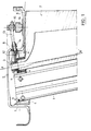
- la figure 1, une vue schématique en coupe axiale d'un exemple de réalisation d'un dispositif de commande de calage d'un aubage directeur d'un turboréacteur, selon l'invention ;
- la figure 2, une vue en perspective et éclatée des moyens de fixation et d'articulation des pivots des aubes mobiles, selon l'invention ;
- la figure 3, une vue en perspective des moyens de fixation et d'articulation des aubes mobiles après montage dans la plate-forme, selon l'invention.
- Figure 1, a schematic view in axial section of an exemplary embodiment of a timing control device of a guide vane of a turbojet, according to the invention;
- Figure 2, a perspective and exploded view of the means for fixing and articulation of the pivots of the movable blades, according to the invention;
- Figure 3, a perspective view of the fixing means and articulation of the movable blades after mounting in the platform, according to the invention.
Dans l'exemple de réalisation représenté sur la figure 1, l'entrée d'air du turboréacteur est munie de bras fixes 1 et d'aubes directrices 2 mobiles autour d'un axe radial XX' passant par des pivots 3 situés aux extrémités supérieures des aubes mobiles 2.
Les bras fixes 1, les aubes mobiles 2 et les pivots 3 sont creux de manière à permettre la circulation de l'air chaud de dégivrage prélevé à la sortie du compresseur haute pression non représenté. Les bras fixes 1 et les pivots 3 des aubes mobiles 2 sont montés dans des plate-formes 4 extérieures mises en contact entre elles, et sont coiffés par un collecteur d'air 5 solidaire d'une virole externe 6.
Les plate-formes 4 comportent deux brides latérales amont 7 et aval 8 qui sont fixées à des brides correspondantes du collecteur 5 par exemple au moyen d'un système de vis et d'écrou. Les plate-formes 4 forment avec le collecteur 5 une enceinte torique qui reçoit, contient et distribue l'air de dégivrage des bras fixes 1 et des aubes mobiles 2. L'étanchéité entre l'intérieur et l'extérieur du collecteur est assurée grâce aux fixations bride contre bride entre le collecteur 5 et les plate-formes 4. Chaque plate-forme 4 comporte sur sa face externe, entre les deux brides latérales 7,8, une région transversale épaisse traversée par deux alésages 9, 10, respectivement amont et aval orientés radialement. Les bras fixes 1 sont encastrés et boulonnés dans le premier alésage amont 9 de la région épaissie de la plate-forme 4. Les pivots 3 des aubes mobiles 2 sont montés dans le deuxième alésage aval 10 et pivotent dans ce deuxième alésage par l'intermédiaire d'une douille creuse de frottement 11 solidaire de la plate-forme 4. Le pivotement des pivots 3 des aubes mobiles 2 autour de l'axe radial XX' est commandé par une biellette constituée de deux parties respectivement amont 12 et aval 13. Les parties amont 12 et aval 13 sont respectivement disposées à l'intérieur et à l'extérieur du collecteur 5. La partie amont 12 est insérée dans l'alésage 10 de la plate-forme 4 par l'intermédiaire de lumières pratiquées respectivement dans le collecteur 5, dans la plate-forme 4 et dans la douille creuse de frottement 11, les différentes lumières étant disposées en regard les unes des autres.In the embodiment shown in Figure 1, the air intake of the turbojet engine is provided with fixed arms 1 and guide
The fixed arms 1, the
The platforms 4 comprise two upstream 7 and downstream 8 side flanges which are fixed to corresponding flanges of the
La partie aval 13 est liée par une première extrémité à la partie amont 12 par l'intermédiaire d'un contre-écrou de blocage 14 et comporte une deuxième extrémité mobile linéairement dans une rotule 15 solidaire d'un anneau de commande et de synchronisation 16. La commande du pivotement de toutes les aubes mobiles est effectuée simultanément par l'intermédiaire de l'anneau de commande de façon connue en soi.The
La figure 2 représente une vue en perspective et éclatée des moyens de fixation et d'articulation des pivots des aubes mobiles, selon l'invention.FIG. 2 represents a perspective and exploded view of the means of fixing and articulation of the pivots of the movable blades, according to the invention.
L'articulation du pivot 3 d'une aube mobile 2 à l'intérieur de l'alésage aval 10 de la plate-forme 4 est effectuée par l'intermédiaire d'une douille creuse de frottement 11. La douille creuse comporte, dans sa région supérieure, une fente 20 circonférentielle de largeur prédéterminée. La douille creuse 11 est mise en place et fixée dans l'alésage aval 10 de la plate-forme 4 de façon que la fente 20 soit disposée en regard de la lumière 21 de la plate-forme 4. La partie amont 12 de la biellette comporte une zone plane percée à son extrémité d'un oeil 22 de forme et de section prédéterminée, par exemple en forme de carré. Cette zone plane est insérée dans l'alésage aval 10 de la plate-forme 4 par l'intermédiaire de la lumière 21 de la plate-forme et de la fente 20 de la douille creuse 11. La forme et la largeur de la fente 20 et de la lumière 21 sont imposées par la cinématique de la biellette 12. Un embout creux 17 est fixé de façon permanente, par exemple par frettage, sur le pivot 3 de l'aube mobile 2. L'embout 17 comporte une partie supérieure filetée 18, une partie intermédiaire 19 de forme et de section prédéterminée, et une partie inférieure dans laquelle est emboîté le pivot 3. La forme de la partie intermédiaire 19 est complémentaire de la forme de l'oeil 22 de la partie amont 12 de la biellette et sa section est légèrement inférieure à celle de l'oeil 22 de manière que lorsque le pivot 3 muni de son embout 17 est mis en place dans l'alésage 10 de la plate-forme 4, la partie intermédiaire 19 s'emboîte dans l'oeil 22 de la biellette 12, l'oeil 22 épousant exactement la forme de la partie intermédiaire 19 de l'embout 17.
Le pivot 3 de l'aube mobile 2 et la partie amont 12 de la biellette sont rendus solidaires en rotation par un moyen de serrage, par exemple un écrou épaulé 23 vissé sur la partie supérieure filetée 18 de l'embout 17.The articulation of the
The
Pour que l'orientation des aubes soit effectuée avec précision, il est nécessaire que l'orientation de la partie intermédiaire 19 de l'embout 17 soit effectué de façon précise par rapport a l'aube mobile 2.
De même, la fente 20 de la douille 11 doit être orientée très précisément par rapport à la plate-forme 4. A cet effet, il est préférable d'utiliser un outillage de montage ou un détrompeur.In order for the orientation of the blades to be carried out with precision, it is necessary for the orientation of the
Likewise, the
Lorsque le pivot 2 muni de son embout 17 est monté dans la plate-forme 4 avec la douille de frottement 11, la partie amont 12 de la biellette et l'écrou 23 de serrage, la plate-forme 4 est mise en place dans le collecteur 5 et les brides latérales amont 7 et aval 8 sont fixées à des brides correspondantes du collecteur 5. A cet effet, les brides latérales 7, 8 comportent plusieurs perçages 24 dans lesquels sont insérés de manière connue des moyens de fixation non représentés.When the
De même, des perçages 25 sont prévus pour assurer la fixation des différentes plate-formes entre-elles.Likewise,
La partie aval 13 de la biellette disposée à l'extérieur du collecteur 5 est alors fixée par une première extrémité à la partie amont 12 par exemple par vissage puis serrage au moyen d'un contre-écrou 14. La partie aval 13 de la biellette comporte une deuxième extrémité par exemple de section carrée, liée à des moyens, non représentés sur la figure 2, de commande et de synchronisation du pivotement des aubes par l'intermédiaire de la rotule 15 solidaire de l'anneau de commande 16.The
La figure 3 est une vue en perspective des moyens de fixation et d'articulation des pivots des aubes mobiles après montage dans la plate-forme, selon l'invention.Figure 3 is a perspective view of the means of fixing and articulation of the pivots of the movable blades after mounting in the platform, according to the invention.
Cette figure montre qu'après montage, (virole extérieure non représentée) les moyens de fixation et d'articulation des pivots des aubes mobiles sont complètement intégrés dans l'alésage aval 10 de la plate forme 4 et occupent un environnement très réduit.This figure shows that after assembly, (external shell not shown) the means for fixing and articulation of the pivots of the movable blades are completely integrated in the
Les pivots 3 des aubes, la douille 11 et l'écrou de serrage 23 étant tous creux, ils permettent l'arrivée de l'air chaud de dégivrage à l'intérieur des aubes mobiles.The
La fente 20 de la douille 11 et la lumière 21 de la plate-forme 4 permettent la manoeuvrabilité du dispositif de commande d'orientation des aubes à calage variable qui est localisé à l'extérieur du collecteur 5.The
Claims (6)
Applications Claiming Priority (2)
| Application Number | Priority Date | Filing Date | Title |
|---|---|---|---|
| FR9603203 | 1996-03-14 | ||
| FR9603203A FR2746141B1 (en) | 1996-03-14 | 1996-03-14 | CONTROL DEVICE FOR INTEGRATED PIVOT IN A MANIFOLD |
Publications (2)
| Publication Number | Publication Date |
|---|---|
| EP0795681A1 true EP0795681A1 (en) | 1997-09-17 |
| EP0795681B1 EP0795681B1 (en) | 2000-04-26 |
Family
ID=9490178
Family Applications (1)
| Application Number | Title | Priority Date | Filing Date |
|---|---|---|---|
| EP97400549A Expired - Lifetime EP0795681B1 (en) | 1996-03-14 | 1997-03-13 | Actuation mechanism for variable inlet vanes in turbomachine compressor |
Country Status (5)
| Country | Link |
|---|---|
| US (1) | US5795128A (en) |
| EP (1) | EP0795681B1 (en) |
| CA (1) | CA2197398C (en) |
| DE (1) | DE69701759T2 (en) |
| FR (1) | FR2746141B1 (en) |
Cited By (3)
| Publication number | Priority date | Publication date | Assignee | Title |
|---|---|---|---|---|
| EP1867877A1 (en) * | 2006-06-16 | 2007-12-19 | Ansaldo Energia S.P.A. | Gas turbine compressor |
| FR2975435A1 (en) * | 2011-05-16 | 2012-11-23 | Snecma | DEVICE FOR DEFROSTING A TURBOMACHINE SEPARATION SPOUT |
| CN114458450A (en) * | 2022-02-10 | 2022-05-10 | 中国航发沈阳发动机研究所 | Aeroengine air inlet machine casket anti-icing structure |
Families Citing this family (20)
| Publication number | Priority date | Publication date | Assignee | Title |
|---|---|---|---|---|
| SE512085C2 (en) * | 1998-05-28 | 2000-01-24 | Abb Ab | A rotor machine arrangement |
| US6019574A (en) * | 1998-08-13 | 2000-02-01 | General Electric Company | Mismatch proof variable stator vane |
| FR2784711B1 (en) | 1998-10-16 | 2001-01-05 | Techlam | VANE VARIABLE SETTING ANGLE CONTROL DEVICE |
| FR2793521B1 (en) | 1999-05-10 | 2005-09-23 | Techlam | VARIABLE CALIBRATION CONTROL ROD |
| US6382906B1 (en) * | 2000-06-16 | 2002-05-07 | General Electric Company | Floating spoolie cup impingement baffle |
| FR2814205B1 (en) | 2000-09-18 | 2003-02-28 | Snecma Moteurs | IMPROVED FLOW VEIN TURBOMACHINE |
| FR2814206B1 (en) | 2000-09-18 | 2002-12-20 | Snecma Moteurs | VARIABLE SETTING BLADE CONTROL DEVICE |
| JP3482196B2 (en) * | 2001-03-02 | 2003-12-22 | 三菱重工業株式会社 | Method and apparatus for assembling and adjusting variable capacity turbine |
| FR2835295B1 (en) | 2002-01-29 | 2004-04-16 | Snecma Moteurs | VANE VARIABLE SETTING ANGLE CONTROL DEVICE WITH PINCH CONNECTION FOR TURBOMACHINE COMPRESSOR RECTIFIER |
| DE10243103A1 (en) * | 2002-09-17 | 2004-03-25 | Rolls-Royce Deutschland Ltd & Co Kg | Device for adjusting the compressor blades of a gas turbine, comprises angled levers mounted on an adjusting ring and coupled to a blade spindle |
| GB0312098D0 (en) * | 2003-05-27 | 2004-05-05 | Rolls Royce Plc | A variable arrangement for a turbomachine |
| FR2857699B1 (en) * | 2003-07-17 | 2007-06-29 | Snecma Moteurs | DEFROSTING DEVICE FOR TURBOMACHINE INPUT DIRECTION WHEEL DARK, DAWN WITH SUCH A DEFROSTING DEVICE, AND AIRCRAFT ENGINE EQUIPPED WITH SUCH AUBES |
| FR2862338B1 (en) * | 2003-11-17 | 2007-07-20 | Snecma Moteurs | DEVICE FOR CONNECTION BETWEEN A DISPENSER AND A SUPPLY ENCLOSURE FOR COOLANT FLUID INJECTORS IN A TURBOMACHINE |
| FR2880926A1 (en) * | 2005-01-14 | 2006-07-21 | Snecma Moteurs Sa | Turbomachine, has stator blades with variable orientation and circular collector to suck air via connections branching to ends of main channels on extreme portions of pivots, where connections have bellow-seals penetrating in channels |
| EP2058524A1 (en) * | 2007-11-12 | 2009-05-13 | Siemens Aktiengesellschaft | Air bleed compressor with variable guide vanes |
| US10704411B2 (en) | 2018-08-03 | 2020-07-07 | General Electric Company | Variable vane actuation system for a turbo machine |
| FR3112368B1 (en) | 2020-07-08 | 2022-08-05 | Safran Aircraft Engines | AIR INLET FOR AN AIRCRAFT TURBOMACHINE, AN AIRCRAFT TURBOMACHINE EQUIPPED WITH SUCH AN AIR INLET AND METHOD FOR MAINTAINING IT |
| FR3115561B1 (en) | 2020-10-23 | 2023-04-21 | Safran Aircraft Engines | AIR INTAKE BLADE FOR AN AIRCRAFT TURBOMACHINE, AIRCRAFT TURBOMACHINE EQUIPPED WITH SUCH AN AIR INTAKE BLADE AND METHOD FOR MANUFACTURING IT |
| CN113530888B (en) * | 2021-08-24 | 2022-08-09 | 中国航发湖南动力机械研究所 | Multi-cavity integrated guide vane casing structure with anti-icing function |
| US11698024B1 (en) | 2022-05-10 | 2023-07-11 | Pratt & Whitney Canada Corp. | System and method of anti-icing inlet guide vanes |
Citations (8)
| Publication number | Priority date | Publication date | Assignee | Title |
|---|---|---|---|---|
| FR1053647A (en) * | 1952-04-05 | 1954-02-03 | Snecma | Gas turbine thruster improvements |
| DE920614C (en) * | 1945-03-08 | 1954-11-25 | Daimler Benz Ag | Pivoting guide vane, especially for cooling and charging fans of aircraft |
| US2823700A (en) * | 1954-11-19 | 1958-02-18 | Westinghouse Electric Corp | Fluid flow control apparatus |
| US2858062A (en) * | 1955-01-24 | 1958-10-28 | Gen Electric | Variable stator mechanism |
| US4139329A (en) * | 1977-05-16 | 1979-02-13 | Westinghouse Canada Limited | Vane tip motion transfer device |
| FR2599785A1 (en) * | 1986-06-04 | 1987-12-11 | Snecma | Variable-pitch air intake directing vane assembly for a jet engine |
| EP0546935A1 (en) * | 1991-12-11 | 1993-06-16 | Societe Nationale D'etude Et De Construction De Moteurs D'aviation "Snecma" | Stator guiding the inlet of air into a turbomachine and procedure for mounting a blade of this stator |
| US5316438A (en) * | 1993-01-29 | 1994-05-31 | Industria De Turbo Propulsores S.A. | Gas turbine engine variable aerofoil vane actuation mechanism |
Family Cites Families (6)
| Publication number | Priority date | Publication date | Assignee | Title |
|---|---|---|---|---|
| US4193738A (en) * | 1977-09-19 | 1980-03-18 | General Electric Company | Floating seal for a variable area turbine nozzle |
| DE2810240C2 (en) * | 1978-03-09 | 1985-09-26 | MTU Motoren- und Turbinen-Union München GmbH, 8000 München | Adjustable grille for turbines with axial flow, in particular high-pressure turbines for gas turbine engines |
| US4214851A (en) * | 1978-04-20 | 1980-07-29 | General Electric Company | Structural cooling air manifold for a gas turbine engine |
| FR2631386A1 (en) * | 1988-05-11 | 1989-11-17 | Snecma | TURBOMACHINE HAVING AN INPUT GRID INCORPORATING OIL PIPING TUBES |
| US5492446A (en) * | 1994-12-15 | 1996-02-20 | General Electric Company | Self-aligning variable stator vane |
| US5593275A (en) * | 1995-08-01 | 1997-01-14 | General Electric Company | Variable stator vane mounting and vane actuation system for an axial flow compressor of a gas turbine engine |
-
1996
- 1996-03-14 FR FR9603203A patent/FR2746141B1/en not_active Expired - Fee Related
-
1997
- 1997-02-12 CA CA002197398A patent/CA2197398C/en not_active Expired - Fee Related
- 1997-03-11 US US08/814,340 patent/US5795128A/en not_active Expired - Fee Related
- 1997-03-13 DE DE69701759T patent/DE69701759T2/en not_active Expired - Fee Related
- 1997-03-13 EP EP97400549A patent/EP0795681B1/en not_active Expired - Lifetime
Patent Citations (8)
| Publication number | Priority date | Publication date | Assignee | Title |
|---|---|---|---|---|
| DE920614C (en) * | 1945-03-08 | 1954-11-25 | Daimler Benz Ag | Pivoting guide vane, especially for cooling and charging fans of aircraft |
| FR1053647A (en) * | 1952-04-05 | 1954-02-03 | Snecma | Gas turbine thruster improvements |
| US2823700A (en) * | 1954-11-19 | 1958-02-18 | Westinghouse Electric Corp | Fluid flow control apparatus |
| US2858062A (en) * | 1955-01-24 | 1958-10-28 | Gen Electric | Variable stator mechanism |
| US4139329A (en) * | 1977-05-16 | 1979-02-13 | Westinghouse Canada Limited | Vane tip motion transfer device |
| FR2599785A1 (en) * | 1986-06-04 | 1987-12-11 | Snecma | Variable-pitch air intake directing vane assembly for a jet engine |
| EP0546935A1 (en) * | 1991-12-11 | 1993-06-16 | Societe Nationale D'etude Et De Construction De Moteurs D'aviation "Snecma" | Stator guiding the inlet of air into a turbomachine and procedure for mounting a blade of this stator |
| US5316438A (en) * | 1993-01-29 | 1994-05-31 | Industria De Turbo Propulsores S.A. | Gas turbine engine variable aerofoil vane actuation mechanism |
Cited By (5)
| Publication number | Priority date | Publication date | Assignee | Title |
|---|---|---|---|---|
| EP1867877A1 (en) * | 2006-06-16 | 2007-12-19 | Ansaldo Energia S.P.A. | Gas turbine compressor |
| WO2007144430A1 (en) * | 2006-06-16 | 2007-12-21 | Ansaldo Energia S.P.A. | Gas turbine compressor |
| US8075253B2 (en) | 2006-06-16 | 2011-12-13 | Ansaldo Energia S.P.A. | Gas turbine compressor |
| FR2975435A1 (en) * | 2011-05-16 | 2012-11-23 | Snecma | DEVICE FOR DEFROSTING A TURBOMACHINE SEPARATION SPOUT |
| CN114458450A (en) * | 2022-02-10 | 2022-05-10 | 中国航发沈阳发动机研究所 | Aeroengine air inlet machine casket anti-icing structure |
Also Published As
| Publication number | Publication date |
|---|---|
| EP0795681B1 (en) | 2000-04-26 |
| FR2746141B1 (en) | 1998-04-17 |
| US5795128A (en) | 1998-08-18 |
| CA2197398C (en) | 2004-04-27 |
| CA2197398A1 (en) | 1997-09-15 |
| DE69701759T2 (en) | 2000-11-30 |
| FR2746141A1 (en) | 1997-09-19 |
| DE69701759D1 (en) | 2000-05-31 |
Similar Documents
| Publication | Publication Date | Title |
|---|---|---|
| EP0795681B1 (en) | Actuation mechanism for variable inlet vanes in turbomachine compressor | |
| EP3074609B1 (en) | Device for guiding synchronizing ring vanes with variable pitch angle of a turbine engine and method for assembling such a device | |
| EP1696104B1 (en) | Actuation of variable geometry guide vanes of a turbomachine | |
| EP1908923B1 (en) | Device for fixing a stator vane in an annular casing of a turbomachine, jet engine including the device and method of installing the stator vane | |
| CA2518355C (en) | Retention of centring keys of the rings under the variable setting stator blades of a gas turbine engine | |
| CA2592791C (en) | Bearing for variable stator blade | |
| EP1696134A2 (en) | Regulation device for centering the unison ring for the variable stator vanes of a turbomachine. | |
| CA2969639C (en) | Ring for controlling a stage of variable-setting vanes for a turbine engine | |
| FR2920492A1 (en) | VARIABLE SHAFT OF AUBES FOR A TURBOMACHINE | |
| FR3009335A1 (en) | TURBOMACHINE VARIABLE ROTATION ANGLE RECTIFIER AUB GUIDING DEVICE | |
| FR3111161A1 (en) | VARIABLE TIMING BLOWER BLADE LOCKING SYSTEM | |
| CA2637646A1 (en) | Turbine engine combustion chamber | |
| EP1469166A1 (en) | Actuation mechanism for variable inlet vanes in a turbomachine | |
| FR2882577A1 (en) | Actuating ring`s centering adjusting device for rotary blade of turbomachine, has brake shoe comprising rod with longitudinal groove, and washer comprising radial pin engaged in groove and radial slots engaged in slots of cavity of ring | |
| EP3084141B1 (en) | Turbine engine compressor, in particular of an aeroplane turboprop or turbofan | |
| EP3710679B1 (en) | Device for holding a radial centripetal air sampling member | |
| FR3072719A1 (en) | CONTROL RING OF A VARIABLE SHIFT AUBRA STAGE FOR A TURBOMACHINE | |
| FR3076325A1 (en) | DEVICE FOR VARIABLE SETTING OF AT LEAST TWO ANNULAR ROWS OF FIXED BLADES FOR A TURBOMACHINE | |
| FR3082227A1 (en) | PILOT COOLING DEVICE FOR A TURBINE OF A TURBOMACHINE | |
| FR3024996A1 (en) | CONTROL RING OF A VARIABLE SHIFT AUBRA STAGE FOR A TURBOMACHINE | |
| FR2881190A1 (en) | Variable pitch stator guide vane actuating device for e.g. aircraft engine, has actuator fixed to casing and acting on bridge, where device that acts on actuating rings is arranged between rings and does not extend beyond rings | |
| EP1674707A1 (en) | Variable area nozzle with one-piece control lever support for a turbomachine | |
| FR3099798A1 (en) | Set for a turbomachine turbine | |
| EP1331402A1 (en) | Stator blade control apparatus | |
| FR3108097A1 (en) | POSITIONING DEVICE FOR A NACELLE HOOD OF AN AIRCRAFT PROPELLER ASSEMBLY |
Legal Events
| Date | Code | Title | Description |
|---|---|---|---|
| PUAI | Public reference made under article 153(3) epc to a published international application that has entered the european phase |
Free format text: ORIGINAL CODE: 0009012 |
|
| 17P | Request for examination filed |
Effective date: 19970401 |
|
| AK | Designated contracting states |
Kind code of ref document: A1 Designated state(s): DE FR GB |
|
| 17Q | First examination report despatched |
Effective date: 19990216 |
|
| GRAG | Despatch of communication of intention to grant |
Free format text: ORIGINAL CODE: EPIDOS AGRA |
|
| GRAG | Despatch of communication of intention to grant |
Free format text: ORIGINAL CODE: EPIDOS AGRA |
|
| GRAH | Despatch of communication of intention to grant a patent |
Free format text: ORIGINAL CODE: EPIDOS IGRA |
|
| GRAH | Despatch of communication of intention to grant a patent |
Free format text: ORIGINAL CODE: EPIDOS IGRA |
|
| GRAA | (expected) grant |
Free format text: ORIGINAL CODE: 0009210 |
|
| AK | Designated contracting states |
Kind code of ref document: B1 Designated state(s): DE FR GB |
|
| GBT | Gb: translation of ep patent filed (gb section 77(6)(a)/1977) |
Effective date: 20000426 |
|
| REF | Corresponds to: |
Ref document number: 69701759 Country of ref document: DE Date of ref document: 20000531 |
|
| PLBE | No opposition filed within time limit |
Free format text: ORIGINAL CODE: 0009261 |
|
| STAA | Information on the status of an ep patent application or granted ep patent |
Free format text: STATUS: NO OPPOSITION FILED WITHIN TIME LIMIT |
|
| 26N | No opposition filed | ||
| REG | Reference to a national code |
Ref country code: GB Ref legal event code: IF02 |
|
| REG | Reference to a national code |
Ref country code: FR Ref legal event code: TP Ref country code: FR Ref legal event code: CD |
|
| PGFP | Annual fee paid to national office [announced via postgrant information from national office to epo] |
Ref country code: FR Payment date: 20050222 Year of fee payment: 9 |
|
| PGFP | Annual fee paid to national office [announced via postgrant information from national office to epo] |
Ref country code: GB Payment date: 20050225 Year of fee payment: 9 Ref country code: DE Payment date: 20050225 Year of fee payment: 9 |
|
| REG | Reference to a national code |
Ref country code: FR Ref legal event code: CD |
|
| PG25 | Lapsed in a contracting state [announced via postgrant information from national office to epo] |
Ref country code: GB Free format text: LAPSE BECAUSE OF NON-PAYMENT OF DUE FEES Effective date: 20060313 |
|
| PG25 | Lapsed in a contracting state [announced via postgrant information from national office to epo] |
Ref country code: DE Free format text: LAPSE BECAUSE OF NON-PAYMENT OF DUE FEES Effective date: 20061003 |
|
| GBPC | Gb: european patent ceased through non-payment of renewal fee |
Effective date: 20060313 |
|
| REG | Reference to a national code |
Ref country code: FR Ref legal event code: ST Effective date: 20061130 |
|
| PG25 | Lapsed in a contracting state [announced via postgrant information from national office to epo] |
Ref country code: FR Free format text: LAPSE BECAUSE OF NON-PAYMENT OF DUE FEES Effective date: 20060331 |