EP0795652A2 - Oil cut-off device for floor drains and similar - Google Patents
Oil cut-off device for floor drains and similar Download PDFInfo
- Publication number
- EP0795652A2 EP0795652A2 EP97103392A EP97103392A EP0795652A2 EP 0795652 A2 EP0795652 A2 EP 0795652A2 EP 97103392 A EP97103392 A EP 97103392A EP 97103392 A EP97103392 A EP 97103392A EP 0795652 A2 EP0795652 A2 EP 0795652A2
- Authority
- EP
- European Patent Office
- Prior art keywords
- liquid
- valve body
- pipe member
- oil
- opening
- Prior art date
- Legal status (The legal status is an assumption and is not a legal conclusion. Google has not performed a legal analysis and makes no representation as to the accuracy of the status listed.)
- Ceased
Links
- 238000012216 screening Methods 0.000 claims abstract description 38
- 238000005273 aeration Methods 0.000 claims abstract description 14
- 239000007788 liquid Substances 0.000 claims description 143
- 238000007789 sealing Methods 0.000 claims description 14
- 239000000356 contaminant Substances 0.000 claims description 3
- 239000007779 soft material Substances 0.000 claims description 3
- 230000001413 cellular effect Effects 0.000 claims description 2
- 230000005484 gravity Effects 0.000 claims description 2
- 239000000463 material Substances 0.000 claims description 2
- 239000002184 metal Substances 0.000 claims 1
- 239000003921 oil Substances 0.000 description 23
- XLYOFNOQVPJJNP-UHFFFAOYSA-N water Substances O XLYOFNOQVPJJNP-UHFFFAOYSA-N 0.000 description 6
- 239000002283 diesel fuel Substances 0.000 description 1
- DNJIEGIFACGWOD-UHFFFAOYSA-N ethanethiol Chemical compound CCS DNJIEGIFACGWOD-UHFFFAOYSA-N 0.000 description 1
- 239000000295 fuel oil Substances 0.000 description 1
- 239000007769 metal material Substances 0.000 description 1
- 230000000630 rising effect Effects 0.000 description 1
Images

Classifications
-
- E—FIXED CONSTRUCTIONS
- E03—WATER SUPPLY; SEWERAGE
- E03F—SEWERS; CESSPOOLS
- E03F5/00—Sewerage structures
- E03F5/04—Gullies inlets, road sinks, floor drains with or without odour seals or sediment traps
- E03F5/0401—Gullies for use in roads or pavements
- E03F5/0405—Gullies for use in roads or pavements with an odour seal
- E03F5/0406—Gullies for use in roads or pavements with an odour seal the odour seal being easily accessible for cleaning
-
- E—FIXED CONSTRUCTIONS
- E03—WATER SUPPLY; SEWERAGE
- E03F—SEWERS; CESSPOOLS
- E03F5/00—Sewerage structures
- E03F5/04—Gullies inlets, road sinks, floor drains with or without odour seals or sediment traps
- E03F5/0407—Floor drains for indoor use
-
- E—FIXED CONSTRUCTIONS
- E03—WATER SUPPLY; SEWERAGE
- E03F—SEWERS; CESSPOOLS
- E03F5/00—Sewerage structures
- E03F5/04—Gullies inlets, road sinks, floor drains with or without odour seals or sediment traps
- E03F2005/0412—Gullies inlets, road sinks, floor drains with or without odour seals or sediment traps with means for adjusting their position with respect to the surrounding surface
- E03F2005/0413—Gullies inlets, road sinks, floor drains with or without odour seals or sediment traps with means for adjusting their position with respect to the surrounding surface for height adjustment
-
- E—FIXED CONSTRUCTIONS
- E03—WATER SUPPLY; SEWERAGE
- E03F—SEWERS; CESSPOOLS
- E03F5/00—Sewerage structures
- E03F5/04—Gullies inlets, road sinks, floor drains with or without odour seals or sediment traps
- E03F2005/0416—Gullies inlets, road sinks, floor drains with or without odour seals or sediment traps with an odour seal
Definitions
- the present invention relates to an oil cut-off device for floor drains or similar, whereby the floor drain comprises a liquid-containing member and a pipe member which is directed down into liquid in said liquid-contaning member such that a liquid seal is defined, whereby the pipe member is adapted to guide liquid down to the liquid seal, whereby the pipe member down below has an opening through which liquid can flow out of said pipe member, whereby a valve seat for a valve body which is located in the pipe member, is provided around the opening, whereby the valve body is provided to float in liquids with higher density than liquid mixed with oil or oil, but sink in liquids which are mixed with oil or consist of oil and thereby have a lower density than the firstmentioned liquids, whereby the valve body is provided to sink to the valve seat and, in cooperation therewith, to close the opening and thereby interrupt the flow of liquid through the floor drain, and whereby at least one screening means is provided in the pipe member and prevents liquid streams, which flow down into the floor drain when the valve body floats in the liquid in
- Oil cut-off devices of the abovementioned type are already known from e.g. SE patent specification 222 843.
- the cut-off means for the valve body at the oil cut-off device according to said publication is provided with openings for allowing liquid to flow thereinto.
- the cut-off means has no air outlet openings which are located so that air can flow out of the upper portions of the cut-off means such that the liquid surface and the valve body can rise high up in said upper portions. Therefore, the cut-off means of this prior art oil cut-off device can not be used in modern floor drains having a small structural height and wherein it is therefore necessary that the liquid surface and valve body can rise high up in the upper portions of the cut-off means. Consequently, nothing is mentioned in said publication that problems may arise if air outlet openings are located in upper portions of the cut-off means and nothing is mentioned about how to eliminate these problems.
- the object of the present invention has been to see to, at oil cut-off devices of the abovementioned type, that the liquid surface and the valve body can rise high up in the cut-off means and simultaneously protect the valve body so that said valve body is not pressed downwards by liquid flowing into the floor drain.
- This is arrived at according to the invention by providing the oil cut-off device according to the invention with the characterizing features of claim 1.
- air may flow out of the cut-off means such that the liquid surface and the valve body can rise high up in said cut-off means, and streams of water are prevented from flowing down into the aeration opening such that they hit the valve body and press it in downwards direction.
- the drawings illustrate a floor drain including an outer member 1 with an upper inlet portion 2, a portion 3 located beneath said inlet portion for receiving and carrying an insert and an outlet pipe 4 extending from said insert-carrying portion 3, said outlet pipe 4 being connectable to a discharge system (not shown).
- the outlet pipe 4 is here directed laterally relative to the insert-carrying portion 3, but may alternatively be directed downwards.
- An insert 5 is removably located in the insert-carrying portion 3 of the floor drain.
- This insert 5 includes a pipe member 6 which at the top has an outwardly directed support flange 7 which is adapted to rest on inwardly directed support surfaces 8 on the outer member 1.
- the pipe member 6 also includes a sealing ring 9 which is in contact with downwardly directed surfaces 10 on the outer member 1, so that a sealing is obtained between said outer member 1 and the insert 5.
- the sealing ring 9 may assist in retaining the insert 5 at the outer member 1.
- the upper portions of the pipe member 6 is provided with a number - preferably four - of downwardly directed flanges 11 having holes 12, the purpose of which will be described below.
- the pipe member 6 includes downwardly directed wall portions 13 which down below transform into lower, inwardly directed wall portions 14 with a centrally located opening 15.
- the wall portions 14 define around the opening 15 an obliquely upwards/inwards directed edge portion 16 with a softly rounded end edge 17.
- This edge portion 16 is adapted to define a valve seat 18 on the pipe member 6.
- the pipe member 6 further includes outer or external flange portions 19 - preferably four flange portions - which extend along the downwardly directed and the inwardly directed wall portions 13, 14.
- the flange portions 19 are inter alia adapted for centering and for keeping the distance between the pipe member and a member 20 containing liquid.
- the pipe member 6 is adapted to extend downwards into the liquid-containing member 20, which preferably consists of a trough with hook portions 21 - preferably four - located at the top thereof. These hook portions 21 are adapted to permit snapping of the liquid-containing member 20 onto the downwardly directed flanges 11 of the pipe member 6 by bringing said hook portions 21 into engagement in the holes 12 of said flanges 11.
- the insert 5 functions so that liquid - normally water - flows down into the pipe member 6 and gathers in the liquid-containing member 20 until it is filled.
- the liquid surface 23 is then situated substantially above the lower, inwardly directed wall portions 14 of the pipe member 6, i.e. the pipe member 6 extends far down into the liquid-containing member 20, whereby a liquid seal 22 - normally called water seal or odour or stench trap - is defined, which prevents odours in the discharge system from rising through the floor drain.
- the pipe member 6 For preventing oil or liquids mixed with oil from flowing out through the floor drain, the pipe member 6 includes a valve body 25 which is adapted to close the opening 15 in cooperation with the valve seat 18.
- This valve body 25 has such a density that it floats in liquids having higher density than liquid mixed with oil or oil and that it sinks in liquids mixed with oil or consisting of oil.
- the valve body 25 may e.g. have a density of about 9,5 kg/dm 3 , which means that it floats in water (with about one tenth above the surface) but sinks in water mixed with oil or in oil, e.g. when fuel oils or Diesel oil flows down into the floor drain.
- valve body 25 sinks, it is brought in contact with the valve seat 18 so that said valve body closes the opening 15 and thus, it is ensured that the liquid mixed with oil or the oil can not flow out into the discharge system through the floor drain.
- the valve body 25 consists e.g. of a substantially cylindrical hollow body 26, which down below is sealed or closed by an underside 27 and at the top by a cap 28.
- the underside 27 has a downwardly directed retaining member 29 which is tubular in shape and which has an outer or external seat 30 for a sealing ring 31. At the top thereof, said sealing ring 31 engages the underside 27 and it is adapted to cooperate down below with the seat 18 for closing the opening 15.
- the inner space 32 of the valve body has an upwardly open member 33 into which a weight 34 can be inserted from above.
- Lower portions of the upwardly open member 33 are situated in inner parts of the retaining member 29, so that the weight 34 can be located as far below as possible in the valve body 25. This means that the valve body 25 can be given a very low centre of gravity.
- the upwardly open member 33 may be cylindrical and the weight 34 may be a cylindrical body of metallic material.
- the cylindrical hollow body 26 has at the top a seat 36 for a sealing ring 37 which is adapted to provide a sealing between said cylindrical hollow body 26 and the cap 28.
- the cap 28 can preferably be snapped onto the cylindrical hollow body 26 so that it can be removed when required for change of weight 34.
- the cylindrical hollow body 26 has down below a lateral, outwardly directed guide flange 38 and the cap 28 defines at the top another guide flange 39 by having a lateral, outwardly directed shape.
- the sealing ring 31 preferably consists of a soft material, which can be formed into the rounded end edge 17 of the valve seat 18 and which also is capable of engaging the valve seat 18 around contaminants adhering thereto.
- This sealing ring 31 may consist of oil resistant cellular rubber material.
- a screening means 40 which is adapted to prevent liquid streams 41, which from above flow down into the pipe member 6, from hitting the valve body 25.
- the valve body 25 when it floats in liquid, is pressed down to the seat 18, and thus, there is no risk that the valve body 25 unintentionally can interrupt the flow through the floor drain.
- the screening means 40 preferably includes a cylindrical member 42 with a larger diameter than the valve body 25.
- This cylindrical member 42 is open down below and has an upper wall portion 43 with preferably a centrally located aeration opening 44 which is adapted to permit air (see arrow 45, fig. 1) to flow out of the screening means 40 when liquid and the valve body 25 rise therein.
- the aeration opening 44 is located so that the liquid streams 41 coming from above can not flow into the screening means 40 from above to such an extent that they affect the valve body 25 in downwards direction towards the valve seat 30.
- the aeration opening 44 may be screened off from above by a casing or cover 46.
- This casing or cover 46 comprises downwardly directed mounting flanges 47 - preferably four such mounting flanges - which makes it possible to snap the cover 46 onto a collar 48 which is provided extending upwards from the upper wall portion 43 around the aeration opening 44.
- the cover 46 is provided to define a laterally directed air slit 49 with the upper wall portion 43 such that air 45 can flow out of the aeration opening 44 in a lateral direction.
- the cover 46 is also provided such that lower parts of the air slit 49 lie on a level below the upper edge 50 of the collar 48.
- the screening means 40 is removably mounted in the pipe member 6 and has outwardly and downwardly directed support legs 51 - preferably four such support legs - which down below are adapted to engage the lower, inwardly directed wall portions 14 of said pipe member 6 so that said legs 51 determine the elevation of the screening means 40 in the pipe member 6.
- the support legs 51 are preferably also adapted to center the screening means 40 relative to the pipe member 6.
- the support legs 51 can form guide portions 52 for guiding the valve body 25 during its movement between its upper position - in which it floats in the liquid - and its lower position - in which it cooperates with the seat 18.
- Said guide portions 52 preferably include members 53 which are located inside the screening means 40 and which may be connected with the cylindrical member 42 as well as with the upper wall portion 43.
- the screening means 40 is designed and located so that it from above covers and receives the major part of the valve body 25 when said valve body floats in the liquid in the liquid seal 22 so that the liquid streams 41 flowing downwards pass said valve body 25 externally thereof in downwards direction towards the opening 15, whereby liquid will flow out of the water seal 22 via the upper edge 24 of the liquid-containing member 20.
- the invention is not limited to the embodiment described above and illustrated in the drawings, but may vary within the scope of the following claims.
- the oil cut-off device may be used in other types of floor drains than the type shown and it may also be used in roof drains.
- the valve body 25 may be of another design than what is illustrated and the screening means 40 may also be designed otherwise than what is shown and may also consist of more than one member.
- the screening means 40 may e.g. be provided so that upper portions thereof are located above the liquid surface 23 in the liquid seal 22, while lower portions thereof are located below said liquid surface 23.
- the screening means 40 may be mounted so that its upper portions are situated in level with upper portions of the pipe member 6 and it may be somewhat higher than half the height of the pipe member 6. If there is an aeration opening 44 in the screening means 40, said opening 44 should preferably be located above the liquid surface 23 in the liquid seal 22.
Landscapes
- Health & Medical Sciences (AREA)
- Life Sciences & Earth Sciences (AREA)
- Engineering & Computer Science (AREA)
- Hydrology & Water Resources (AREA)
- Public Health (AREA)
- Water Supply & Treatment (AREA)
- Pipe Accessories (AREA)
- Float Valves (AREA)
- Types And Forms Of Lifts (AREA)
- Sink And Installation For Waste Water (AREA)
- Self-Closing Valves And Venting Or Aerating Valves (AREA)
Abstract
Description
- The present invention relates to an oil cut-off device for floor drains or similar, whereby the floor drain comprises a liquid-containing member and a pipe member which is directed down into liquid in said liquid-contaning member such that a liquid seal is defined, whereby the pipe member is adapted to guide liquid down to the liquid seal, whereby the pipe member down below has an opening through which liquid can flow out of said pipe member, whereby a valve seat for a valve body which is located in the pipe member, is provided around the opening, whereby the valve body is provided to float in liquids with higher density than liquid mixed with oil or oil, but sink in liquids which are mixed with oil or consist of oil and thereby have a lower density than the firstmentioned liquids, whereby the valve body is provided to sink to the valve seat and, in cooperation therewith, to close the opening and thereby interrupt the flow of liquid through the floor drain, and whereby at least one screening means is provided in the pipe member and prevents liquid streams, which flow down into the floor drain when the valve body floats in the liquid in the liquid seal, from pressing said valve body in downwards direction to the valve seat.
- Oil cut-off devices of the abovementioned type are already known from e.g. SE patent specification 222 843. The cut-off means for the valve body at the oil cut-off device according to said publication is provided with openings for allowing liquid to flow thereinto. However, the cut-off means has no air outlet openings which are located so that air can flow out of the upper portions of the cut-off means such that the liquid surface and the valve body can rise high up in said upper portions. Therefore, the cut-off means of this prior art oil cut-off device can not be used in modern floor drains having a small structural height and wherein it is therefore necessary that the liquid surface and valve body can rise high up in the upper portions of the cut-off means. Consequently, nothing is mentioned in said publication that problems may arise if air outlet openings are located in upper portions of the cut-off means and nothing is mentioned about how to eliminate these problems.
- The object of the present invention has been to see to, at oil cut-off devices of the abovementioned type, that the liquid surface and the valve body can rise high up in the cut-off means and simultaneously protect the valve body so that said valve body is not pressed downwards by liquid flowing into the floor drain. This is arrived at according to the invention by providing the oil cut-off device according to the invention with the characterizing features of
claim 1. - By locating the air outlet or aeration opening at the top of the cut-off means and by screening off said cut-off means by means of the casing or cover, air may flow out of the cut-off means such that the liquid surface and the valve body can rise high up in said cut-off means, and streams of water are prevented from flowing down into the aeration opening such that they hit the valve body and press it in downwards direction.
- The invention will be further described below with reference to the accompanying drawings, wherein
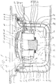
- fig. 1 is a vertical section of a floor drain having an oil cut-off device according to the invention, whereby a valve body is situated in an upper opening position;
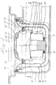
- fig. 2 is a vertical section corresponding to fig. 1, whereby the valve body is situated in a lower closing position;
- fig. 3 is a section along the line III-III through the floor drain of fig. 1;
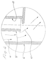
- fig. 4 illustrates an enlarged part of the section of the floor drain according to fig. 1; and
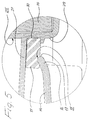
- fig. 5 illustrates another enlarged part of the section of the floor drain according to fig. 1.
- The drawings illustrate a floor drain including an
outer member 1 with anupper inlet portion 2, aportion 3 located beneath said inlet portion for receiving and carrying an insert and anoutlet pipe 4 extending from said insert-carryingportion 3, saidoutlet pipe 4 being connectable to a discharge system (not shown). Theoutlet pipe 4 is here directed laterally relative to the insert-carryingportion 3, but may alternatively be directed downwards. - An insert 5 is removably located in the insert-carrying
portion 3 of the floor drain. This insert 5 includes apipe member 6 which at the top has an outwardly directed support flange 7 which is adapted to rest on inwardly directed support surfaces 8 on theouter member 1. At the top, thepipe member 6 also includes asealing ring 9 which is in contact with downwardly directedsurfaces 10 on theouter member 1, so that a sealing is obtained between saidouter member 1 and the insert 5. The sealingring 9 may assist in retaining the insert 5 at theouter member 1. - The upper portions of the
pipe member 6 is provided with a number - preferably four - of downwardly directedflanges 11 havingholes 12, the purpose of which will be described below. - The
pipe member 6 includes downwardly directedwall portions 13 which down below transform into lower, inwardly directedwall portions 14 with a centrally located opening 15. Thewall portions 14 define around theopening 15 an obliquely upwards/inwards directededge portion 16 with a softly rounded end edge 17. Thisedge portion 16 is adapted to define avalve seat 18 on thepipe member 6. - The
pipe member 6 further includes outer or external flange portions 19 - preferably four flange portions - which extend along the downwardly directed and the inwardly directedwall portions flange portions 19 are inter alia adapted for centering and for keeping the distance between the pipe member and amember 20 containing liquid. Thepipe member 6 is adapted to extend downwards into the liquid-containingmember 20, which preferably consists of a trough with hook portions 21 - preferably four - located at the top thereof. Thesehook portions 21 are adapted to permit snapping of the liquid-containingmember 20 onto the downwardly directedflanges 11 of thepipe member 6 by bringing saidhook portions 21 into engagement in theholes 12 of saidflanges 11. - The insert 5 functions so that liquid - normally water - flows down into the
pipe member 6 and gathers in the liquid-containingmember 20 until it is filled. Theliquid surface 23 is then situated substantially above the lower, inwardly directedwall portions 14 of thepipe member 6, i.e. thepipe member 6 extends far down into the liquid-containingmember 20, whereby a liquid seal 22 - normally called water seal or odour or stench trap - is defined, which prevents odours in the discharge system from rising through the floor drain. - If more liquid flows down into the pipe member 6 - after the liquid-containing
member 20 is filled - liquid will flow over theupper edge 24 thereof and down into theouter member 1 and through theoutlet pipe 4 into the discharge system. - For preventing oil or liquids mixed with oil from flowing out through the floor drain, the
pipe member 6 includes avalve body 25 which is adapted to close theopening 15 in cooperation with thevalve seat 18. Thisvalve body 25 has such a density that it floats in liquids having higher density than liquid mixed with oil or oil and that it sinks in liquids mixed with oil or consisting of oil. Thevalve body 25 may e.g. have a density of about 9,5 kg/dm3, which means that it floats in water (with about one tenth above the surface) but sinks in water mixed with oil or in oil, e.g. when fuel oils or Diesel oil flows down into the floor drain. - When the
valve body 25 sinks, it is brought in contact with thevalve seat 18 so that said valve body closes theopening 15 and thus, it is ensured that the liquid mixed with oil or the oil can not flow out into the discharge system through the floor drain. - The
valve body 25 consists e.g. of a substantially cylindricalhollow body 26, which down below is sealed or closed by anunderside 27 and at the top by acap 28. - The
underside 27 has a downwardly directed retainingmember 29 which is tubular in shape and which has an outer orexternal seat 30 for asealing ring 31. At the top thereof, said sealingring 31 engages theunderside 27 and it is adapted to cooperate down below with theseat 18 for closing theopening 15. - The
inner space 32 of the valve body has an upwardlyopen member 33 into which aweight 34 can be inserted from above. Lower portions of the upwardlyopen member 33 are situated in inner parts of the retainingmember 29, so that theweight 34 can be located as far below as possible in thevalve body 25. This means that thevalve body 25 can be given a very low centre of gravity. - The upwardly
open member 33 may be cylindrical and theweight 34 may be a cylindrical body of metallic material. - The cylindrical
hollow body 26 has at the top aseat 36 for asealing ring 37 which is adapted to provide a sealing between said cylindricalhollow body 26 and thecap 28. Thecap 28 can preferably be snapped onto the cylindricalhollow body 26 so that it can be removed when required for change ofweight 34. Furthermore, the cylindricalhollow body 26 has down below a lateral, outwardly directedguide flange 38 and thecap 28 defines at the top anotherguide flange 39 by having a lateral, outwardly directed shape. - The sealing
ring 31 preferably consists of a soft material, which can be formed into the rounded end edge 17 of thevalve seat 18 and which also is capable of engaging thevalve seat 18 around contaminants adhering thereto. Thissealing ring 31 may consist of oil resistant cellular rubber material. - In the
pipe member 6 there is provided a screening means 40 which is adapted to preventliquid streams 41, which from above flow down into thepipe member 6, from hitting thevalve body 25. Hereby, it is prevented that thevalve body 25, when it floats in liquid, is pressed down to theseat 18, and thus, there is no risk that thevalve body 25 unintentionally can interrupt the flow through the floor drain. - The screening means 40 preferably includes a
cylindrical member 42 with a larger diameter than thevalve body 25. Thiscylindrical member 42 is open down below and has anupper wall portion 43 with preferably a centrally locatedaeration opening 44 which is adapted to permit air (seearrow 45, fig. 1) to flow out of the screening means 40 when liquid and thevalve body 25 rise therein. Theaeration opening 44 is located so that theliquid streams 41 coming from above can not flow into the screening means 40 from above to such an extent that they affect thevalve body 25 in downwards direction towards thevalve seat 30. In order to prevent or obstruct the flow ofliquid streams 41 into the screening means 40, the aeration opening 44 may be screened off from above by a casing orcover 46. This casing orcover 46 comprises downwardly directed mounting flanges 47 - preferably four such mounting flanges - which makes it possible to snap thecover 46 onto a collar 48 which is provided extending upwards from theupper wall portion 43 around the aeration opening 44. - The
cover 46 is provided to define a laterally directedair slit 49 with theupper wall portion 43 such thatair 45 can flow out of the aeration opening 44 in a lateral direction. Thecover 46 is also provided such that lower parts of theair slit 49 lie on a level below theupper edge 50 of the collar 48. - The screening means 40 is removably mounted in the
pipe member 6 and has outwardly and downwardly directed support legs 51 - preferably four such support legs - which down below are adapted to engage the lower, inwardly directedwall portions 14 of saidpipe member 6 so that saidlegs 51 determine the elevation of the screening means 40 in thepipe member 6. Thesupport legs 51 are preferably also adapted to center the screening means 40 relative to thepipe member 6. - The
support legs 51 can formguide portions 52 for guiding thevalve body 25 during its movement between its upper position - in which it floats in the liquid - and its lower position - in which it cooperates with theseat 18. Saidguide portions 52 preferably includemembers 53 which are located inside the screening means 40 and which may be connected with thecylindrical member 42 as well as with theupper wall portion 43. - As is apparent from fig. 2, the screening means 40 is designed and located so that it from above covers and receives the major part of the
valve body 25 when said valve body floats in the liquid in theliquid seal 22 so that theliquid streams 41 flowing downwards pass saidvalve body 25 externally thereof in downwards direction towards theopening 15, whereby liquid will flow out of thewater seal 22 via theupper edge 24 of the liquid-containingmember 20. - The invention is not limited to the embodiment described above and illustrated in the drawings, but may vary within the scope of the following claims. As not specifically described alternatives one should mention that the oil cut-off device may be used in other types of floor drains than the type shown and it may also be used in roof drains. The
valve body 25 may be of another design than what is illustrated and the screening means 40 may also be designed otherwise than what is shown and may also consist of more than one member. The screening means 40 may e.g. be provided so that upper portions thereof are located above theliquid surface 23 in theliquid seal 22, while lower portions thereof are located below saidliquid surface 23. Furthermore, the screening means 40 may be mounted so that its upper portions are situated in level with upper portions of thepipe member 6 and it may be somewhat higher than half the height of thepipe member 6. If there is anaeration opening 44 in the screening means 40, saidopening 44 should preferably be located above theliquid surface 23 in theliquid seal 22.
Claims (14)
- Oil cut-off device for floor drains or similar,whereby the floor drain comprises a liquid-containing member (20) and a pipe member (6) which is directed down into liquid in said liquid-contaning member (20) such that a liquid seal (22) is defined,whereby the pipe member (6) is adapted to guide liquid down to the liquid seal (22),whereby the pipe member (6) down below has an opening (15) through which liquid can flow out of said pipe member (6),whereby a valve seat (18) for a valve body (25) which is located in the pipe member (6), is provided around the opening (15),whereby the valve body (25) is provided to float in liquids with higher density than liquid mixed with oil or oil, but sink in liquids which are mixed with oil or consist of oil and thereby have a lower density than the firstmentioned liquids,whereby the valve body (25) is provided to sink to the valve seat (18) and, in cooperation therewith, to close the opening (15) and thereby interrupt the flow of liquid through the floor drain, andwhereby at least one screening means (40) is provided in the pipe member (6) and prevents liquid streams (41), which flow down into the floor drain when the valve body (25) floats in the liquid in the liquid seal (22) from pressing said valve body (25) in downwards direction to the valve seat (18),
characterized inthat the screening means (40) includes a cover (46) which from above screens off at least one aeration opening (44) which is located at the top of said screening means (40) and adapted to permit air (45) to flow out of said screening means (40) when the liquid surface (23) in the liquid seal (22) and the valve body (25) rise in the screening means (40), and that the cover (46) is located so that liquid streams (41) can not flow into the screening means (40) through the aeration opening (44) to such an extent that they press the valve body (25) in downwards direction to the valve seat (18). - Oil cut-off device according to claim 1, characterized in that the cover (46) is provided to define a laterally directed air slit (49) such that air (45) can flow out through the aeration opening (44) in at least one lateral direction.
- Oil cut-off device according to claim 2, characterized in that the upper wall portion (14) has an upwardly directed collar (48) which is located around the aeration opening (44), that the cover (46) has downwardly directed mounting flanges (47) through which said cover (46) can be snapped onto the collar (48), and that the cover (46) is provided so that lower portions of the air slit (49) are located at a level beneath an upper edge (50) of the collar (48).
- Oil cut-off device for floor drains or similar,whereby the floor drain comprises a liquid-containing member (20) and a pipe member (6) which is directed down into liquid in said liquid-contaning member (20) such that a liquid seal (22) is defined,whereby the pipe member (6) is adapted to guide liquid down to the liquid seal (22),whereby the pipe member (6) down below has an opening (15) through which liquid can flow out of said pipe member (6),whereby a valve seat (18) for a valve body (25) which is located in the pipe member (6), is provided around the opening (15),whereby the valve body (25) is provided to float in liquids with higher density than liquid mixed with oil or oil, but sink in liquids which are mixed with oil or consist of oil and thereby have a lower density than the firstmentioned liquids,whereby the valve body (25) is provided to sink to the valve seat (18) and, in cooperation therewith, to close the opening (15) and thereby interrupt the flow of liquid through the floor drain, and whereby at least one screening means (40) is provided in the pipe member (6) and prevents liquid streams (41), which flow down into the floor drain when the valve body (25) floats in the liquid in the liquid seal (22) from pressing said valve body (25) in downwards direction to the valve seat (18),
characterized inthat the screening means (40) is removably positioned in the pipe member (6) and has outwardly and downwardly directed support legs (51) which are adapted to engage lower, inwardly directed wall portions (14) of said pipe member (6) for determining the elevation of the screening means (40) in said pipe member (6), whereby said support legs (51) preferably also are adapted to center said screening means (40) relative to said pipe member (6). - Oil cut-off device according to claim 4, characterized in that the support legs (51) of the screening means (40) define guide portions (52) for guiding the valve body (25) during its movements in vertical direction between an upper position in which it floats in liquid in the liquid seal (22) and a lower position in which it cooperates with the seat (18).
- Oil cut-off device according to claim 5, characterized in that the guide portions (52) include members (53) located inside the screening means (40).
- Oil cut-off device for floor drains or similar,whereby the floor drain comprises a liquid-containing member (20) and a pipe member (6) which is directed down into liquid in said liquid-contaning member (20) such that a liquid seal (22) is defined,whereby the pipe member (6) is adapted to guide liquid down to the liquid seal (22),whereby the pipe member (6) down below has an opening (15) through which liquid can flow out of said pipe member (6),whereby a valve seat (18) for a valve body (25) which is located in the pipe member (6), is provided around the opening (15),whereby the valve body (25) is provided to float in liquids with higher density than liquid mixed with oil or oil, but sink in liquids which are mixed with oil or consist of oil and thereby have a lower density than the firstmentioned liquids,whereby the valve body (25) is provided to sink to the valve seat (18) and, in cooperation therewith, to close the opening (15) and thereby interrupt the flow of liquid through the floor drain,whereby at least one screening means (40) is provided in the pipe member (6) and prevents liquid streams (41), which flow down into the floor drain when the valve body (25) floats in the liquid in the liquid seal (22) from pressing said valve body (25) in downwards direction to the valve seat (18), andwhereby the valve body (25) down below is provided with a sealing ring (31) which is adapted to be brought in contact with the valve seat (18) for closing the opening (15) in the pipe member (6),
characterized inthat the sealing ring (31) consists of such soft material that it can adapt itself to contaminants adhering to the valve seat (18) and thereby engage said valve seat (18) around said contaminants. - Oil cut-off device according to claim 7, characterized in that the sealing ring (31) consists of such soft material that it can adapt itself to the softly rounded shape of an end edge (17) of such an obliquely upwards/inwards directed edge portion (16) of the valve seat (18) which is defined by the pipe member (6) around the opening (15).
- Oil cut-off device according to claim 7 or 8, characterized in that the sealing ring (31) consists of an oil resistant cellular rubber material.
- Oil cut-off device for floor drains or similar,whereby the floor drain comprises a liquid-containing member (20) and a pipe member (6) which is directed down into liquid in said liquid-contaning member (20) such that a liquid seal (22) is defined,whereby the pipe member (6) is adapted to guide liquid down to the liquid seal (22),whereby the pipe member (6) down below has an opening (15) through which liquid can flow out of said pipe member (6),whereby a valve seat (18) for a valve body (25) which is located in the pipe member (6), is provided around the opening (15),whereby the valve body (25) is provided to float in liquids with higher density than liquid mixed with oil or oil, but sink in liquids which are mixed with oil or consist of oil and thereby have a lower density than the firstmentioned liquids,whereby the valve body (25) is provided to sink to the valve seat (18) and, in cooperation therewith, to close the opening (15) and thereby interrupt the flow of liquid through the floor drain, andwhereby at least one screening means (40) is provided in the pipe member (6) and prevents liquid streams (41), which flow down into the floor drain when the valve body (25) floats in the liquid in the liquid seal (22) from pressing said valve body (25) in downwards direction to the valve seat (18),
characterized inthat the valve body (25) includes a cap (28) which can be sealingly connected thereto and which permits opening of the valve body (25) at the top thereof for removable location of a weight (34) in lower portions of an inner space in said valve body (25), said weight being adapted to give said valve body (25) a predetermined weight. - Oil cut-off device according to claim 10, characterized in that the inner space (32) of the valve body (25) includes an in upwards direction open member (33) which is designed to receive and position the weight (34) and that lower portions of said upwardly open member (33) are situated in a retaining member (29) which is directed downwards from an underside (27) of the valve body (25) and on which a sealing ring (31) forming part of said valve body (25) is mounted externally, whereby said valve body (25) attains a low centre of gravity.
- Oil cut-off device according to claim 10 or 11, characterized in that the weight is a metal body (34).
- Oil cut-off device for floor drains or similar,whereby the floor drain comprises a liquid-containing member (20) and a pipe member (6) which is directed down into liquid in said liquid-contaning member (20) such that a liquid seal (22) is defined,whereby the pipe member (6) is adapted to guide liquid down to the liquid seal (22),whereby the pipe member (6) down below has an opening (15) through which liquid can flow out of said pipe member (6),whereby a valve seat (18) for a valve body (25) which is located in the pipe member (6), is provided around the opening (15),whereby the valve body (25) is provided to float in liquids with higher density than liquid mixed with oil or oil, but sink in liquids which are mixed with oil or consist of oil and thereby have a lower density than the firstmentioned liquids,whereby the valve body (25) is provided to sink to the valve seat (18) and, in cooperation therewith, to close the opening (15) and thereby interrupt the flow of liquid through the floor drain, andwhereby at least one screening means (40) is provided in the pipe member (6) and prevents liquid streams (41), which flow down into the floor drain when the valve body (25) floats in the liquid in the liquid seal (22) from pressing said valve body (25) in downwards direction to the valve seat (18),
characterized inthat the valve body (25) has a substantially cylindrical hollow body (26) which down below is sealed or closed by an underside (27) and at the top by a removable cap (28), that the cylindrical hollow body (26) down below is provided with a lateral, outwardly directed, annular guide flange (38), and that the cylindrical hollow body (26) at the top has a lateral, outwardly directed guide flange (39) which preferably is defined by the cap (28), whereby said annular guide flanges (38, 39) are adapted to cooperate with guide portions (52) which are provided on the screening means (40) and which preferably are defined by support legs (51) for said screening means (40). - Oil cut-off device for floor drains or similar,whereby the floor drain comprises a liquid-containing member (20) and a pipe member (6) which is directed down into liquid in said liquid-contaning member (20) such that a liquid seal (22) is defined,whereby the pipe member (6) is adapted to guide liquid down to the liquid seal (22),whereby the pipe member (6) down below has an opening (15) through which liquid can flow out of said pipe member (6),whereby a valve seat (18) for a valve body (25) which is located in the pipe member (6), is provided around the opening (15),whereby the valve body (25) is provided to float in liquids with higher density than liquid mixed with oil or oil, but sink in liquids which are mixed with oil or consist of oil and thereby have a lower density than the firstmentioned liquids,whereby the valve body (25) is provided to sink to the valve seat (18) and, in cooperation therewith, to close the opening (15) and thereby interrupt the flow of liquid through the floor drain, andwhereby at least one screening means (40) is provided in the pipe member (6) and prevents liquid streams (41), which flow down into the floor drain when the valve body (25) floats in the liquid in the liquid seal (22) from pressing said valve body (25) in downwards direction to the valve seat (18),
characterized inthat the liquid-containing member (20) is located on the pipe member (6) and that the pipe member (6) is provided as an insert (5) in an outer member (1) of a floor drain or similar, whereby said insert (5) besides said pipe member (6) also includes said liquid-containing member (20), the valve body (25) and the screening means (40) and whereby said insert (5) is removably mounted in said outer member (1).
Priority Applications (1)
| Application Number | Priority Date | Filing Date | Title |
|---|---|---|---|
| EP02011316A EP1233112A3 (en) | 1996-03-15 | 1997-03-01 | Oil cut-off device for floor drains or similar |
Applications Claiming Priority (2)
| Application Number | Priority Date | Filing Date | Title |
|---|---|---|---|
| SE9600990 | 1996-03-15 | ||
| SE9600990A SE509047C2 (en) | 1996-03-15 | 1996-03-15 | Oil shut-off device for floor wells |
Related Child Applications (1)
| Application Number | Title | Priority Date | Filing Date |
|---|---|---|---|
| EP02011316A Division EP1233112A3 (en) | 1996-03-15 | 1997-03-01 | Oil cut-off device for floor drains or similar |
Publications (2)
| Publication Number | Publication Date |
|---|---|
| EP0795652A2 true EP0795652A2 (en) | 1997-09-17 |
| EP0795652A3 EP0795652A3 (en) | 1997-11-26 |
Family
ID=20401797
Family Applications (2)
| Application Number | Title | Priority Date | Filing Date |
|---|---|---|---|
| EP97103392A Ceased EP0795652A3 (en) | 1996-03-15 | 1997-03-01 | Oil cut-off device for floor drains and similar |
| EP02011316A Withdrawn EP1233112A3 (en) | 1996-03-15 | 1997-03-01 | Oil cut-off device for floor drains or similar |
Family Applications After (1)
| Application Number | Title | Priority Date | Filing Date |
|---|---|---|---|
| EP02011316A Withdrawn EP1233112A3 (en) | 1996-03-15 | 1997-03-01 | Oil cut-off device for floor drains or similar |
Country Status (4)
| Country | Link |
|---|---|
| EP (2) | EP0795652A3 (en) |
| NO (1) | NO970998L (en) |
| PL (1) | PL183303B1 (en) |
| SE (1) | SE509047C2 (en) |
Cited By (7)
| Publication number | Priority date | Publication date | Assignee | Title |
|---|---|---|---|---|
| EP1026330A3 (en) * | 1999-02-08 | 2002-10-02 | Ab Sjöbo Bruk | Device at water seals for floor drains |
| DE10220254A1 (en) * | 2002-05-06 | 2003-11-27 | Ewald Kowol | Odor lock for use in a substantially vertical waste water drainage shaft comprises a float unit which in both closed and open states is provided with a guide for its vertical motion |
| EP1571269A1 (en) * | 2004-03-04 | 2005-09-07 | Kessel GmbH | Floor drain |
| EP1703032A1 (en) * | 2005-02-21 | 2006-09-20 | Kessel GmbH | Floor drain insert and light liquids separator |
| WO2013177852A1 (en) * | 2012-06-01 | 2013-12-05 | 北京康之维科技有限公司 | Self-cleaning method and device for double-layer water seal floating bell jar |
| CN109281382A (en) * | 2017-07-20 | 2019-01-29 | 施海月 | A kind of odour-proof floor drain |
| CN115012508A (en) * | 2022-06-27 | 2022-09-06 | 艾力利荣化工科技(惠州)有限公司 | Industrial floor drain device with high protection level |
Families Citing this family (8)
| Publication number | Priority date | Publication date | Assignee | Title |
|---|---|---|---|---|
| KR101053995B1 (en) * | 2008-10-08 | 2011-08-03 | (주) 디아이엔바이로 | Oil / water separator |
| CN103362180B (en) * | 2009-12-30 | 2014-11-05 | 戴永锋 | Floating cover safety floor drain |
| CN103374969B (en) * | 2009-12-30 | 2014-09-03 | 戴永锋 | Safety floor drain with floating cover |
| CN101701470B (en) * | 2009-12-30 | 2013-10-23 | 戴永锋 | Floating cover safety floor drain |
| CN101906810A (en) * | 2010-07-29 | 2010-12-08 | 江苏万邦建设集团有限公司 | Pre-embedded type anti-seepage floor drain |
| CN203684351U (en) * | 2013-12-06 | 2014-07-02 | 谢水清 | Long-efficiency fully-closed water-seal deodorization water trap |
| CN106836451A (en) * | 2017-02-21 | 2017-06-13 | 陈晓鸿 | The assembly method of one-touch intelligent floor drain |
| CN111173112B (en) * | 2020-01-19 | 2020-12-18 | 徐州工程学院 | A double deodorant floor drain device |
Family Cites Families (5)
| Publication number | Priority date | Publication date | Assignee | Title |
|---|---|---|---|---|
| SE222843C1 (en) * | 1968-09-24 | |||
| CH273026A (en) * | 1949-04-19 | 1951-01-31 | Von Roll Ag | Floor drain with odor trap. |
| DE3025637A1 (en) * | 1980-07-07 | 1982-04-22 | Passavant-Werke Michelbacher Hütte, 6209 Aarbergen | Versatile odour sealed floor drain housing - has different dia. upward and downward pipes used as stand-pipe and connecting socket |
| US4577653A (en) * | 1983-06-30 | 1986-03-25 | Masco Corporation | Anti-siphon and anti-knock diverter valve |
| DE9405108U1 (en) * | 1994-03-25 | 1994-05-26 | Metallwerke Gebr. Seppelfricke Gmbh & Co, 45881 Gelsenkirchen | Pipe aerator for final line ventilation of drinking water installations |
-
1996
- 1996-03-15 SE SE9600990A patent/SE509047C2/en not_active IP Right Cessation
-
1997
- 1997-03-01 EP EP97103392A patent/EP0795652A3/en not_active Ceased
- 1997-03-01 EP EP02011316A patent/EP1233112A3/en not_active Withdrawn
- 1997-03-05 NO NO970998A patent/NO970998L/en not_active Application Discontinuation
- 1997-03-14 PL PL97318968A patent/PL183303B1/en not_active IP Right Cessation
Cited By (7)
| Publication number | Priority date | Publication date | Assignee | Title |
|---|---|---|---|---|
| EP1026330A3 (en) * | 1999-02-08 | 2002-10-02 | Ab Sjöbo Bruk | Device at water seals for floor drains |
| DE10220254A1 (en) * | 2002-05-06 | 2003-11-27 | Ewald Kowol | Odor lock for use in a substantially vertical waste water drainage shaft comprises a float unit which in both closed and open states is provided with a guide for its vertical motion |
| EP1571269A1 (en) * | 2004-03-04 | 2005-09-07 | Kessel GmbH | Floor drain |
| EP1703032A1 (en) * | 2005-02-21 | 2006-09-20 | Kessel GmbH | Floor drain insert and light liquids separator |
| WO2013177852A1 (en) * | 2012-06-01 | 2013-12-05 | 北京康之维科技有限公司 | Self-cleaning method and device for double-layer water seal floating bell jar |
| CN109281382A (en) * | 2017-07-20 | 2019-01-29 | 施海月 | A kind of odour-proof floor drain |
| CN115012508A (en) * | 2022-06-27 | 2022-09-06 | 艾力利荣化工科技(惠州)有限公司 | Industrial floor drain device with high protection level |
Also Published As
| Publication number | Publication date |
|---|---|
| NO970998D0 (en) | 1997-03-05 |
| PL318968A1 (en) | 1997-09-29 |
| EP0795652A3 (en) | 1997-11-26 |
| EP1233112A2 (en) | 2002-08-21 |
| SE9600990D0 (en) | 1996-03-15 |
| NO970998L (en) | 1997-09-16 |
| EP1233112A3 (en) | 2002-12-18 |
| SE9600990L (en) | 1997-09-16 |
| SE509047C2 (en) | 1998-11-30 |
| PL183303B1 (en) | 2002-06-28 |
Similar Documents
| Publication | Publication Date | Title |
|---|---|---|
| EP0795652A2 (en) | Oil cut-off device for floor drains and similar | |
| US5062735A (en) | Self sealing domed sewer cover assembly | |
| US20120152950A1 (en) | Buoyant plug for emergency drain in floating roof tank | |
| KR20010071201A (en) | Stench trap for a urinal | |
| KR101274762B1 (en) | Water trap for sanitary appliances | |
| EP0486954B1 (en) | Water-trap | |
| US5028320A (en) | Sewer catch basin with gas seal for a petroleum refinery or chemical processing plant | |
| GB2134940A (en) | Drainage gully trap | |
| US7976701B2 (en) | Drain trap | |
| JPH0429176Y2 (en) | ||
| JP2010048030A (en) | Drainage trap | |
| US3397714A (en) | Mechanical gas seal for floor drain traps and the like having means for sealing in the trap and at a cover therefor | |
| US4681131A (en) | Liquid closing device | |
| EP0137021B1 (en) | Level regulating bottom valve device for liquid receptacles | |
| JP2010053610A (en) | Splash preventing device, and pipe joint and catch basin provided with splash preventing device | |
| WO1997007298A1 (en) | A skimmer | |
| JP2589815Y2 (en) | Air valve | |
| JP2509946Y2 (en) | Cleaning port lid | |
| WO2015125034A1 (en) | Safety valve, with a buoyant valve member, in particular for tanks carried by vehicles | |
| KR200395729Y1 (en) | Drain apparatus for cut-off foul smell | |
| GB2280383A (en) | Gravity separator | |
| JPH06226006A (en) | Oil water separator | |
| JPH0960105A (en) | Wastewater manhole | |
| JP3046564U (en) | Oil container that does not drip | |
| KR200388665Y1 (en) | Drainage device |
Legal Events
| Date | Code | Title | Description |
|---|---|---|---|
| PUAI | Public reference made under article 153(3) epc to a published international application that has entered the european phase |
Free format text: ORIGINAL CODE: 0009012 |
|
| AK | Designated contracting states |
Kind code of ref document: A2 Designated state(s): BE CH DE DK FI FR GB LI NL SE |
|
| PUAL | Search report despatched |
Free format text: ORIGINAL CODE: 0009013 |
|
| AK | Designated contracting states |
Kind code of ref document: A3 Designated state(s): BE CH DE DK FI FR GB LI NL SE |
|
| 17P | Request for examination filed |
Effective date: 19980519 |
|
| 17Q | First examination report despatched |
Effective date: 20001201 |
|
| STAA | Information on the status of an ep patent application or granted ep patent |
Free format text: STATUS: THE APPLICATION HAS BEEN REFUSED |
|
| 18R | Application refused |
Effective date: 20020722 |