EP0794476B1 - Vorrichtung zur gravimetrischen Dosierung eines Gemisches - Google Patents
Vorrichtung zur gravimetrischen Dosierung eines Gemisches Download PDFInfo
- Publication number
- EP0794476B1 EP0794476B1 EP19960203425 EP96203425A EP0794476B1 EP 0794476 B1 EP0794476 B1 EP 0794476B1 EP 19960203425 EP19960203425 EP 19960203425 EP 96203425 A EP96203425 A EP 96203425A EP 0794476 B1 EP0794476 B1 EP 0794476B1
- Authority
- EP
- European Patent Office
- Prior art keywords
- collection container
- container
- stock
- collection
- opening
- Prior art date
- Legal status (The legal status is an assumption and is not a legal conclusion. Google has not performed a legal analysis and makes no representation as to the accuracy of the status listed.)
- Expired - Lifetime
Links
- 239000000203 mixture Substances 0.000 title claims description 16
- 238000005303 weighing Methods 0.000 claims description 22
- 239000000428 dust Substances 0.000 claims description 8
- 239000000654 additive Substances 0.000 description 12
- 230000001143 conditioned effect Effects 0.000 description 2
- 238000006073 displacement reaction Methods 0.000 description 2
- 230000005484 gravity Effects 0.000 description 2
- 241001465754 Metazoa Species 0.000 description 1
- 240000004922 Vigna radiata Species 0.000 description 1
- 239000003674 animal food additive Substances 0.000 description 1
- 238000013329 compounding Methods 0.000 description 1
- 238000010276 construction Methods 0.000 description 1
- 230000001186 cumulative effect Effects 0.000 description 1
- 238000007599 discharging Methods 0.000 description 1
- 230000000694 effects Effects 0.000 description 1
- 230000001771 impaired effect Effects 0.000 description 1
- 239000000463 material Substances 0.000 description 1
- 238000005259 measurement Methods 0.000 description 1
- 238000009827 uniform distribution Methods 0.000 description 1
Images
Classifications
-
- G—PHYSICS
- G01—MEASURING; TESTING
- G01G—WEIGHING
- G01G13/00—Weighing apparatus with automatic feed or discharge for weighing-out batches of material
- G01G13/02—Means for automatically loading weigh pans or other receptacles, e.g. disposable containers, under control of the weighing mechanism
- G01G13/022—Material feeding devices
- G01G13/024—Material feeding devices by gravity
-
- G—PHYSICS
- G01—MEASURING; TESTING
- G01G—WEIGHING
- G01G19/00—Weighing apparatus or methods adapted for special purposes not provided for in the preceding groups
- G01G19/22—Weighing apparatus or methods adapted for special purposes not provided for in the preceding groups for apportioning materials by weighing prior to mixing them
- G01G19/32—Weighing apparatus or methods adapted for special purposes not provided for in the preceding groups for apportioning materials by weighing prior to mixing them using two or more weighing apparatus
-
- G—PHYSICS
- G05—CONTROLLING; REGULATING
- G05D—SYSTEMS FOR CONTROLLING OR REGULATING NON-ELECTRIC VARIABLES
- G05D11/00—Control of flow ratio
- G05D11/02—Controlling ratio of two or more flows of fluid or fluent material
- G05D11/13—Controlling ratio of two or more flows of fluid or fluent material characterised by the use of electric means
- G05D11/131—Controlling ratio of two or more flows of fluid or fluent material characterised by the use of electric means by measuring the values related to the quantity of the individual components
- G05D11/133—Controlling ratio of two or more flows of fluid or fluent material characterised by the use of electric means by measuring the values related to the quantity of the individual components with discontinuous action
- G05D11/134—Controlling ratio of two or more flows of fluid or fluent material characterised by the use of electric means by measuring the values related to the quantity of the individual components with discontinuous action by sensing the weight of the individual components
Definitions
- the present invention relates to a device for gravimetric metering of a mixture of several components according to the preamble of claim 1.
- Such a device is known from US 4 733 971.
- This known device is designed for metering the components of a mixture of feed additives for animals.
- the known device comprises a row of stock containers, each containing one of the additives.
- An elongated second collection container extends below the outflow openings of these stock containers.
- the second collection container is divided into compartments, each compartment extending below a corresponding stock container.
- the known device has the disadvantage that the second weighing means, which measure the weight of the additives fed into the second collection container, are necessarily of an expensive design and special measures need to be taken to isolate the second weighing means from its support. Furthermore the second weighing means need to be placed in a conditioned environment in order to obtain accurate measurements. This will be explained below.
- the object of the present invention is to solve the abovementioned problem.
- the invention provides a device according to the preamble of claim 1, which is characterized in that the second collection container is movable below the outflow openings of the stock containers.
- the second collection container can be placed directly below the outflow opening of a stock container from which a relatively low weight of a component of the mixture is being delivered.
- the size of the second collection container can be much smaller and the weight of the second collection container can be reduced. Another advantage is that the number of stock containers can be expanded without altering the second collection container or the second weighing means.
- the first collection container and the second collection container are preferably accommodated in a common frame, which is movable along a path below the outflow openings of the stock containers.
- the path along which the two collection containers are movable can be, for example, a straight line or a more or less freely definable path between two successive positions of the collection container concerned, which can be achieved by, for example, a X-Y displacement mechanism.
- first collection container prefferably designed such that it extends below several outflow openings of different stock containers
- second collection container prefferably designed such that it extends below a smaller number, for example one, of the outflow openings, the second collection container being movable relative to the first collection container, so that the second collection container can be placed below a desired outflow opening without moving the first collection container. This gives great flexibility and efficiency when constantly changing mixtures have to be made.
- the second collection container can swivel about a swivel shaft situated above the first collection container, the second collection container having two collection compartments arranged bottom-to-bottom, each having at the side facing away from the other collection compartment an opening for receiving and delivering a component, while an arm connects the second collection container to the swivel shaft, so that the second collection container can be swivelled between a first receiving position for receiving a component from a first outflow opening and a second receiving position for receiving a component from a second outflow opening, and the contents of a collection compartment are delivered to the first collection container during the swivelling from one receiving position to the other receiving position.
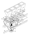
- the device shown diagrammatically in the drawing for gravimetric metering of a mixture of several components comprises a large number of stock containers placed next to each other in a single row, only four of which are shown. These stock containers are indicated by the reference numbers 1, 2, 3 and 4 respectively.
- Each stock container 1, 2, 3, 4 contains one of the components from which many different mixtures can be compounded using the device according to the invention.
- Each stock container has an outflow opening which can be controlled by a controllable valve 5, 6, 7 and 8 respectively, for delivering a metered quantity of the component concerned.
- a control device 9 is provided for controlling the valves 5, 6, 7, 8.
- the device also comprises a first collection container 10, for receiving components from the stock containers 1 - 4.
- the first collection container 10 is accommodated in a frame 11, which is movable along a path below the outflow openings of the stock containers 1 - 4.
- the frame 11 in this example is placed by means of runners on two parallel rails 12, forming the path which in this example is straight. Due to the fact that the first collection container 10 can be moved below the outflow openings of the stock containers, said collection container can be made relatively small and can consequently have a low unloaded weight.
- the low unloaded weight of the first collection container 10 improves the accuracy of determination of the weight of the contents of that collection container 10.
- First weighing means are provided for determining the weight of the contents of the first collection container 10.
- said first weighing means comprise three load cells 13 in a triangular arrangement around the first collection container 10.
- One load cell 13 can be seen in the drawing.
- the first collection container 10 rests by way of the three load cells 13 on the frame 11.
- the load cells 13 are connected to an electrical unit 14, which converts the signals of the load cells 13 into a signal which represents the weight of the contents of the first collection container 10.
- a second collection container 15 is also provided, which container clearly has a smaller volume than the first collection container 10.
- the second collection container 15 is likewise accommodated in the frame 11, so that the second collection container 15 can also be moved below the outflow openings of the stock containers 1 - 4.
- the second collection container 15 is situated above the first collection container 10.
- the second collection container 15 can receive one or more components from the stock containers, but in considerably smaller volume than the much larger first collection container 10.
- the second collection container 15 is designed for delivering the contents of the second collection container 15 to the first collection container 10, for compounding the desired mixture.
- Second weighing means are provided for determining the weight of the contents of the second collection container 15.
- the second weighing means comprise four electronic load cells 17, three of which can be seen in Figure 1.
- the second collection container 15 rests directly on the frame 11 by way of the four load cells 17.
- the load cells 17 are connected to a second electrical signal processing unit 18, which converts the signals of the load cells 17 into a signal which represents the weight of the contents of the second collection container 15.
- Both the unit 14 and the unit 18 are connected to the control device 9, which operates the valves of the stock containers, so that automatic metering of the components can be achieved.
- first weighing means are preferably specifically suitable for weighing the relatively large weight of the contents of the first collection container 10.
- the second weighing means are preferably specifically suitable for accurately weighing considerably smaller weights. An accurate composition of the mixture can be obtained in this way.
- the first collection container 10 is in fact only a bin with an open top side which is so large that said opening extends below several - in this example two - outflow openings of different stock containers.
- the second collection container 15 is smaller, so that it extends below one outflow opening of a stock container. This configuration means that it is possible simultaneously to make one component flow out of stock container 2 into the first collection container 10 and another component to flow out of stock container 1 into the second collection container 15.
- the second collection container 15 is preferably movable relative to the first collection container 10, so that the second collection container 15 can be placed below a desired outflow opening without moving the first collection container 10.
- the first collection container could extend below four outflow openings and the second collection container could always extend below two of said outflow openings.
- the movement of the second collection container 15 is achieved through the fact that the second collection container 15 can swivel about a swivel shaft 20 situated above the first collection container 10.
- the swivel shaft 20 of the second collection container 15 is immovably connected at each end to a supporting bar 21 of a light, but rigid construction situated outside the opening of the first collection container 10.
- the two load cells 17 by means of which the weight of the contents of the second collection container 15 can be determined are situated between each supporting bar 21 and the frame 11.
- the swivel shaft 20 could be fitted on a surround of the opening of the first collection container 10, while the load cells - for example three in number - are placed between the rigid surround and the frame.
- the second collection container 15 has two collection compartments 22, 23, each having at the side facing away from the other collection compartment an opening for receiving and delivering a component.
- An arm 24 connects the two collection compartments 22, 23 to the swivel shaft 20, so that the second collection container 15 can be swivelled between a first receiving position for receiving a component from a first outflow opening, for example from stock container 1, as shown in Figure 1, and a second receiving position for receiving a component from a second outflow opening, for example from stock container 2.
- the second collection container 15 When the collection compartment 22 has been filled with a metered quantity of a component from the stock container 1, the second collection container 15 is swung to the other receiving position below the stock container 2, using means which are not shown here, preferably along the underside of the swivel shaft 20, then the contents of a collection compartment 22 then fall into the first collection container 10 during the swivelling movement. If the swivelling movement is made at sufficient speed, the contents are strewn over the material already present in the first collection container 10, which can be advantageous for achieving a uniform distribution of the component having the smaller weight percentage in the mixture.
- the drawing does not show that the frame 11 is connected to drive means which enable movement of the frame 11 along the rails 12. Together with the control device 9, these drive means can form part of a control unit which permits fully automatic operation of the device.
- the first collection container 10 is provided on the underside with an outflow opening which can be shut off by a valve 30, for discharging the mixture obtained.
- the number of stock containers can be different from what is shown here and can also be placed in a different arrangement, for example in two parallel rows.
- an advantageous embodiment is that in which the first collection container extends below two stock containers of each row, thus in total below four stock containers, and the second collection container extends below two of those four stock containers.
- An X-Y displacement mechanism can also be provided, for example by fitting the rails 12 in such a way that they in turn are movable on rails extending at right angles thereto.
- the device is provided with air suction means, said air suction means comprising air intake openings distributed around the opening of the first collection container.
- the air intake openings are arranged to suck in air from outside the first collection container thereby creating a screen of flowing air which carries along dust escaping from the opening of the first collection container.
- a volume of a component is fed into the first collection container an equal volume of air has to escape from this container.
- the escaping air dust will try to escape from the container which has to be prevented.
- By providing a screen of flowing air around the top opening of the first collection container the dust will not pass this air screen. It is important that the air for forming the screen is not coming from inside the first collection container but from the outside. Sucking in the air from inside the container would have as unwanted effect that more dust or even metered fine components are removed from this container and also the accuracy of the second weighing means could be impaired.
- each stock container is provided with a cover plate extending essentially above the first collection container when said first collection container is positioned under the stock container, the first collection container being provided with brushes arranged around the opening of the first collection container, said brushes wiping over the underside of the cover plate when the first collection container passes under the stock container.
- the cover plate reduce the escape of dust from the first collection container.
- the brushes are located inside the ring of air intake openings, and the brushes are spaced apart so that air and dust can escape from the first collection container but is then removed by the screen of air.
Landscapes
- Physics & Mathematics (AREA)
- General Physics & Mathematics (AREA)
- Engineering & Computer Science (AREA)
- Automation & Control Theory (AREA)
- Sampling And Sample Adjustment (AREA)
- Weight Measurement For Supplying Or Discharging Of Specified Amounts Of Material (AREA)
Claims (12)
- Vorrichtung zur gravimetrischen Dosierung eines Gemisches von mehreren Komponenten, umfassend:dadurch gekennzeichnet, daßmehrere Vorratsbehälter (1-4), von denen jeder zum Aufnehmen einer einzelnen Komponente der Komponenten dient, wobei jeder Vorratsbehälter eine steuerbare Ausfließöffnung (5-8) zum Abgeben einer dosierten Menge der betreffenden Komponente dient;einen ersten Sammelbehälter (10), der unter der Ausfließöffnung einer oder mehrerer Vorratsbehälter plaziert ist, zum Aufnehmen von Komponenten aus den Vorratsbehältern; undeine erste Wiegevorrichtung (13, 14) zum Bestimmen des Gewichts des Inhalts des ersten Sammelbehälters, wobei ein zweiter Sammelbehälter (15) über dem ersten Sammelbehälter (10) plaziert und zum Abgeben des Inhalts des zweiten Sammelbehälters an den ersten Sammelbehälter gestaltet ist; undeine zweite Wiegevorrichtung (17, 18) zum Bestimmen des Gewichtes des Inhaltes des zweiten Sammelbehälters,
der zweite Sammelbehälter (15) unter die Ausfließöffnungen der Vorratsbehälter bewegbar ist. - Vorrichtung nach Anspruch 1, bei welcher der erste Sammelbehälter (10) unter die Ausfließöffnungen (5-8) der Vorratsbehälter (1-4) bewegbar ist.
- Vorrichtung nach Anspruch 2, bei welcher der erste Sammelbehälter (10) und der zweite Sammelbehälter (15) in einem gemeinsamen Gestell (11) untergebracht sind, das unter die Ausfließöffnungen der Vorratsbehälter bewegbar ist.
- Vorrichtung nach Anspruch 3, bei welcher der erste Sammelbehälter (10) von der ersten Wiegevorrichtung (13) auf dem Gestell (11) getragen wird, und bei welcher der zweite Sammelbehälter (15) von der zweiten Wiegevorrichtung (17) auf dem Gestell (11) getragen wird.
- Vorrichtung nach einem oder mehreren der vorhergehenden Ansprüche, bei der der erste Sammelbehälter (10) so gestaltet ist, daß er sich unter mehrere Ausfließöffnungen unterschiedlicher Vorratsbehälter erstreckt, und bei welcher der zweite Sammelbehälter (15) so gestaltet ist, daß er sich unter eine kleinere Anzahl von Ausfließöffnungen erstreckt als der erste Sammelbehälter (10), wobei der zweite Sammelbehälter relativ zum ersten Sammelbehälter bewegbar ist, derart, daß der zweite Sammelbehälter unter einer gewünschten Ausfließöffnung ohne Bewegen des ersten Sammelbehälters plaziert werden kann.
- Vorrichtung nach einem oder mehreren der vorhergehenden Ansprüche, bei welcher der zweite Sammelbehälter (15) um eine Drehachse (20), die über dem ersten Sammelbehälter (10) angeordnet ist, zwischen einer Aufnahmeposition zum Aufnehmen einer Komponente aus einer Aüstließöffnung eines Vorratsbehälters und einer Abgabeposition zum Abgeben des Inhalts des zweiten Sammelbehälters an den ersten Sammelbehälter schwenken kann.
- Vorrichtung nach einem oder mehreren der vorhergehenden Ansprüche, bei der der zweite Sammelbehälter (15) um eine Drehachse (20) geschwenkt werden kann, die über dem ersten Sammelbehälter plaziert ist, wobei der zweite Sammelbehälter zwei Sammelfächer (22, 23) aufweist, von denen jedes an der von dem anderen Sammelfach wegweisenden Seite eine Öffnung zum Aufnehmen und Abgeben einer Komponente aufweist, wobei ein Arm (24) den zweiten Sammelbehälter an die Drehachse (20) anschließt, so daß der zweite Sammelbehälter zwischen einer ersten Aufnahmeposition zum Aufnehmen einer, von einer ersten Ausfließöffnung kommenden Komponente, und einer zweiten Aufnahmeposition zum Aufnehmen einer, von einer zweiten Ausfließöffnung kommenden Komponente geschwenkt werden kann, und daß der Inhalt eines Sammelfaches während des Schwenkens von der einen aufnehmenden Position zu der anderen aufnehmenden Position an den ersten Sammelbehälter abgegeben wird.
- Vorrichtung nach Anspruch 7, bei der die Drehachse (20) des zweiten Sammelbehälters (15) unbeweglich an einem Tragelement (21) befestigt ist, das sich außerhalb der Öffnung des ersten Sammelbehälters (10) erstreckt, während die zweite Wiegevorrichtung zwischen dem Tragelement (21) und dem Gestell (11) plaziert ist.
- Vorrichtung nach einem oder mehreren der vorhergehenden Ansprüche, bei der Luftansaugeinrichtungen vorgesehen sind, wobei die Luftansaugeinrichtungen Lufteinlaßöffnungen umfassen, die um die Öffnung des ersten Sammelbehälters herum verteilt sind.
- Vorrichtung nach Anspruch 9, bei der die Lufteinlaßöffnungen derart angeordnet sind, daß sie Luft außerhalb des ersten Sammelbehälters ansaugen, wodurch ein Schirm strömender Luft erzeugt wird der Staub mit sich führt, welcher aus der Öffnung des ersten Sammelbehälters entweicht.
- Vorrichtung nach einem oder mehreren der vorhergehenden Ansprüche, bei der jeder Vorratsbehälter mit einer Abdeckplatte versehen ist, die sich im wesentlichen über dem ersten Sammelbehälter erstreckt, wenn der erste Sammelbehälter unter dem Vorratsbehälter positioniert ist, wobei der erste Sammelbehälter mit Bürsten versehen ist, die um die Öffnung des ersten Sammelbehälters herum angeordnet sind, wobei die Bürsten über die Unterseite der Abdeckplatte wischen, wenn der erste Sammelbehälter sich unter den Vorratsbehälter schiebt.
- Vorrichtung nach Anspruch 11, bei der die Bürsten innerhalb des Rings von Lufteinlaßöffnungen plaziert sind, und bei der die Bürsten so voneinander beabstandet sind, daß Luft und Staub aus dem ersten Sammelbehälter entweichen kann.
Applications Claiming Priority (2)
| Application Number | Priority Date | Filing Date | Title |
|---|---|---|---|
| NL1001835 | 1995-12-06 | ||
| NL1001835A NL1001835C2 (nl) | 1995-12-06 | 1995-12-06 | Inrichting voor het gravimetrisch doseren van een mengsel. |
Publications (2)
| Publication Number | Publication Date |
|---|---|
| EP0794476A1 EP0794476A1 (de) | 1997-09-10 |
| EP0794476B1 true EP0794476B1 (de) | 2000-09-27 |
Family
ID=19761987
Family Applications (1)
| Application Number | Title | Priority Date | Filing Date |
|---|---|---|---|
| EP19960203425 Expired - Lifetime EP0794476B1 (de) | 1995-12-06 | 1996-12-03 | Vorrichtung zur gravimetrischen Dosierung eines Gemisches |
Country Status (4)
| Country | Link |
|---|---|
| EP (1) | EP0794476B1 (de) |
| DE (1) | DE69610485T2 (de) |
| DK (1) | DK0794476T3 (de) |
| NL (1) | NL1001835C2 (de) |
Families Citing this family (8)
| Publication number | Priority date | Publication date | Assignee | Title |
|---|---|---|---|---|
| DE19744979A1 (de) * | 1997-10-13 | 1999-04-15 | Karl Schmidt Spedition Gmbh & | Wiegeeinrichtung für das Verladen von Schüttgut und Verladeverfahren mit einer solchen Wiegeeinrichtung |
| DE102004002626A1 (de) * | 2004-01-16 | 2005-08-04 | Bühler AG | Waage |
| DE102008046960A1 (de) | 2008-09-12 | 2010-03-25 | Azo Holding Gmbh | Anlage zur gravimetrischen Dosierung verschiedener Schüttkomponenten |
| WO2013185236A1 (en) * | 2012-06-15 | 2013-12-19 | Matiss Inc. | System and method for dispensing bulk material |
| CN104310079B (zh) * | 2014-08-27 | 2016-12-07 | 华中科技大学无锡研究院 | 一种多工位自动循环称重喂料机 |
| CN105092002B (zh) * | 2015-07-28 | 2018-09-18 | 正将自动化设备(江苏)有限公司 | 微量配方计量装置 |
| CN105466533B (zh) * | 2015-09-30 | 2018-08-21 | 珠海格莱利摩擦材料有限公司 | 多工位称重机及方法 |
| CN118495785B (zh) * | 2024-07-17 | 2024-09-27 | 山东龙光天旭太阳能有限公司 | 一种电熔窑炉全自动配料投料装置 |
Family Cites Families (3)
| Publication number | Priority date | Publication date | Assignee | Title |
|---|---|---|---|---|
| US4733971A (en) * | 1986-02-26 | 1988-03-29 | Micro Chemical, Inc. | Programmable weight sensitive microingredient feed additive delivery system and method |
| JPS63283733A (ja) * | 1987-05-14 | 1988-11-21 | Fuji Photo Film Co Ltd | 粉体計量混合装置 |
| JPH0629226A (ja) * | 1992-07-10 | 1994-02-04 | Nec Corp | 気相成長装置 |
-
1995
- 1995-12-06 NL NL1001835A patent/NL1001835C2/nl not_active IP Right Cessation
-
1996
- 1996-12-03 DE DE1996610485 patent/DE69610485T2/de not_active Expired - Fee Related
- 1996-12-03 DK DK96203425T patent/DK0794476T3/da active
- 1996-12-03 EP EP19960203425 patent/EP0794476B1/de not_active Expired - Lifetime
Also Published As
| Publication number | Publication date |
|---|---|
| DE69610485T2 (de) | 2001-03-22 |
| DE69610485D1 (de) | 2000-11-02 |
| NL1001835C2 (nl) | 1997-06-10 |
| DK0794476T3 (da) | 2001-02-12 |
| EP0794476A1 (de) | 1997-09-10 |
Similar Documents
| Publication | Publication Date | Title |
|---|---|---|
| KR0154118B1 (ko) | 포장하지 않은 재료성분들의 중력에 의한 분리를 위한 공기흡입콘베이어시설 | |
| US4525071A (en) | Additive inventory control, batching and delivery system | |
| US4538693A (en) | Weighing machine | |
| US7504593B2 (en) | Continuous quantitative discharging device and material blending system using the same | |
| JP3707794B2 (ja) | 材料混合装置 | |
| US4733971A (en) | Programmable weight sensitive microingredient feed additive delivery system and method | |
| EP0794476A1 (de) | Vorrichtung zur gravimetrischen Dosierung eines Gemisches | |
| US11913824B2 (en) | Combination weighing device | |
| US11971292B2 (en) | Combinatorial weighing device | |
| EP3892969B1 (de) | Kombinationswägevorrichtung | |
| US6981529B2 (en) | Measuring catalyst(s) for filling reactor tubes in reactor vessels | |
| EP0105756B1 (de) | Kombinatorischer Wägeapparat und Methode | |
| WO1998005932A1 (en) | Multi-recipe dosing system | |
| US4766964A (en) | Apparent density measuring device | |
| EP0181738B1 (de) | Vorrichtung zum Steuern des Durchflusses | |
| GB2131963A (en) | Combination weighing machines and method | |
| JP7455481B2 (ja) | 組合せ計量装置 | |
| US4467882A (en) | Automatic weighing apparatus | |
| CN216468646U (zh) | 一种容量可调的颗粒供料装置 | |
| CN217533320U (zh) | 一种旋转投料装置 | |
| JPH0257847B2 (de) | ||
| CN218317690U (zh) | 一种数粒与称重快速切换下料装置 | |
| JP3587618B2 (ja) | 組合せ計量装置 | |
| JPH0514181Y2 (de) | ||
| CN223239220U (zh) | 一种配料添加装置 |
Legal Events
| Date | Code | Title | Description |
|---|---|---|---|
| PUAI | Public reference made under article 153(3) epc to a published international application that has entered the european phase |
Free format text: ORIGINAL CODE: 0009012 |
|
| 17P | Request for examination filed |
Effective date: 19961203 |
|
| AK | Designated contracting states |
Kind code of ref document: A1 Designated state(s): BE CH DE DK FR GB IT LI NL |
|
| GRAG | Despatch of communication of intention to grant |
Free format text: ORIGINAL CODE: EPIDOS AGRA |
|
| 17Q | First examination report despatched |
Effective date: 19990920 |
|
| GRAG | Despatch of communication of intention to grant |
Free format text: ORIGINAL CODE: EPIDOS AGRA |
|
| GRAH | Despatch of communication of intention to grant a patent |
Free format text: ORIGINAL CODE: EPIDOS IGRA |
|
| GRAH | Despatch of communication of intention to grant a patent |
Free format text: ORIGINAL CODE: EPIDOS IGRA |
|
| GRAA | (expected) grant |
Free format text: ORIGINAL CODE: 0009210 |
|
| RAP1 | Party data changed (applicant data changed or rights of an application transferred) |
Owner name: ALFRA DOSEER- EN WEEGSYSTEMEN B.V. |
|
| AK | Designated contracting states |
Kind code of ref document: B1 Designated state(s): BE CH DE DK FR GB IT LI NL |
|
| REG | Reference to a national code |
Ref country code: CH Ref legal event code: EP |
|
| REF | Corresponds to: |
Ref document number: 69610485 Country of ref document: DE Date of ref document: 20001102 |
|
| ITF | It: translation for a ep patent filed | ||
| REG | Reference to a national code |
Ref country code: CH Ref legal event code: NV Representative=s name: RIEDERER HASLER & PARTNER PATENTANWAELTE AG |
|
| ET | Fr: translation filed | ||
| REG | Reference to a national code |
Ref country code: DK Ref legal event code: T3 |
|
| PLBE | No opposition filed within time limit |
Free format text: ORIGINAL CODE: 0009261 |
|
| STAA | Information on the status of an ep patent application or granted ep patent |
Free format text: STATUS: NO OPPOSITION FILED WITHIN TIME LIMIT |
|
| 26N | No opposition filed | ||
| REG | Reference to a national code |
Ref country code: GB Ref legal event code: IF02 |
|
| PGFP | Annual fee paid to national office [announced via postgrant information from national office to epo] |
Ref country code: NL Payment date: 20090630 Year of fee payment: 13 Ref country code: DK Payment date: 20090422 Year of fee payment: 13 |
|
| PGFP | Annual fee paid to national office [announced via postgrant information from national office to epo] |
Ref country code: DE Payment date: 20090422 Year of fee payment: 13 |
|
| REG | Reference to a national code |
Ref country code: CH Ref legal event code: PCAR Free format text: RIEDERER HASLER & PARTNER PATENTANWAELTE AG;ELESTASTRASSE 8;7310 BAD RAGAZ (CH) |
|
| PGFP | Annual fee paid to national office [announced via postgrant information from national office to epo] |
Ref country code: BE Payment date: 20090428 Year of fee payment: 13 |
|
| PGFP | Annual fee paid to national office [announced via postgrant information from national office to epo] |
Ref country code: FR Payment date: 20090625 Year of fee payment: 13 Ref country code: CH Payment date: 20090428 Year of fee payment: 13 |
|
| PGFP | Annual fee paid to national office [announced via postgrant information from national office to epo] |
Ref country code: GB Payment date: 20090629 Year of fee payment: 13 |
|
| PGFP | Annual fee paid to national office [announced via postgrant information from national office to epo] |
Ref country code: IT Payment date: 20090630 Year of fee payment: 13 |
|
| BERE | Be: lapsed |
Owner name: *ALFRA DOSEER- EN WEEGSYSTEMEN B.V. Effective date: 20091231 |
|
| REG | Reference to a national code |
Ref country code: NL Ref legal event code: V1 Effective date: 20100701 |
|
| REG | Reference to a national code |
Ref country code: CH Ref legal event code: PL |
|
| REG | Reference to a national code |
Ref country code: DK Ref legal event code: EBP |
|
| GBPC | Gb: european patent ceased through non-payment of renewal fee |
Effective date: 20091203 |
|
| REG | Reference to a national code |
Ref country code: FR Ref legal event code: ST Effective date: 20100831 |
|
| PG25 | Lapsed in a contracting state [announced via postgrant information from national office to epo] |
Ref country code: NL Free format text: LAPSE BECAUSE OF NON-PAYMENT OF DUE FEES Effective date: 20100701 Ref country code: LI Free format text: LAPSE BECAUSE OF NON-PAYMENT OF DUE FEES Effective date: 20091231 Ref country code: FR Free format text: LAPSE BECAUSE OF NON-PAYMENT OF DUE FEES Effective date: 20091231 Ref country code: CH Free format text: LAPSE BECAUSE OF NON-PAYMENT OF DUE FEES Effective date: 20091231 Ref country code: BE Free format text: LAPSE BECAUSE OF NON-PAYMENT OF DUE FEES Effective date: 20091231 |
|
| PG25 | Lapsed in a contracting state [announced via postgrant information from national office to epo] |
Ref country code: DE Free format text: LAPSE BECAUSE OF NON-PAYMENT OF DUE FEES Effective date: 20100701 |
|
| PG25 | Lapsed in a contracting state [announced via postgrant information from national office to epo] |
Ref country code: GB Free format text: LAPSE BECAUSE OF NON-PAYMENT OF DUE FEES Effective date: 20091203 |
|
| PG25 | Lapsed in a contracting state [announced via postgrant information from national office to epo] |
Ref country code: DK Free format text: LAPSE BECAUSE OF NON-PAYMENT OF DUE FEES Effective date: 20100104 |
|
| PG25 | Lapsed in a contracting state [announced via postgrant information from national office to epo] |
Ref country code: IT Free format text: LAPSE BECAUSE OF NON-PAYMENT OF DUE FEES Effective date: 20091203 |