EP0793929A1 - Adjustable office chair - Google Patents
Adjustable office chair Download PDFInfo
- Publication number
- EP0793929A1 EP0793929A1 EP97200574A EP97200574A EP0793929A1 EP 0793929 A1 EP0793929 A1 EP 0793929A1 EP 97200574 A EP97200574 A EP 97200574A EP 97200574 A EP97200574 A EP 97200574A EP 0793929 A1 EP0793929 A1 EP 0793929A1
- Authority
- EP
- European Patent Office
- Prior art keywords
- chair
- seat
- seat part
- tilting
- gas spring
- Prior art date
- Legal status (The legal status is an assumption and is not a legal conclusion. Google has not performed a legal analysis and makes no representation as to the accuracy of the status listed.)
- Granted
Links
Images


Classifications
-
- A—HUMAN NECESSITIES
- A47—FURNITURE; DOMESTIC ARTICLES OR APPLIANCES; COFFEE MILLS; SPICE MILLS; SUCTION CLEANERS IN GENERAL
- A47C—CHAIRS; SOFAS; BEDS
- A47C1/00—Chairs adapted for special purposes
- A47C1/02—Reclining or easy chairs
- A47C1/031—Reclining or easy chairs having coupled concurrently adjustable supporting parts
- A47C1/032—Reclining or easy chairs having coupled concurrently adjustable supporting parts the parts being movably-coupled seat and back-rest
- A47C1/03255—Reclining or easy chairs having coupled concurrently adjustable supporting parts the parts being movably-coupled seat and back-rest with a central column, e.g. rocking office chairs
-
- A—HUMAN NECESSITIES
- A47—FURNITURE; DOMESTIC ARTICLES OR APPLIANCES; COFFEE MILLS; SPICE MILLS; SUCTION CLEANERS IN GENERAL
- A47C—CHAIRS; SOFAS; BEDS
- A47C1/00—Chairs adapted for special purposes
- A47C1/02—Reclining or easy chairs
- A47C1/031—Reclining or easy chairs having coupled concurrently adjustable supporting parts
- A47C1/032—Reclining or easy chairs having coupled concurrently adjustable supporting parts the parts being movably-coupled seat and back-rest
- A47C1/03261—Reclining or easy chairs having coupled concurrently adjustable supporting parts the parts being movably-coupled seat and back-rest characterised by elastic means
- A47C1/03266—Reclining or easy chairs having coupled concurrently adjustable supporting parts the parts being movably-coupled seat and back-rest characterised by elastic means with adjustable elasticity
-
- A—HUMAN NECESSITIES
- A47—FURNITURE; DOMESTIC ARTICLES OR APPLIANCES; COFFEE MILLS; SPICE MILLS; SUCTION CLEANERS IN GENERAL
- A47C—CHAIRS; SOFAS; BEDS
- A47C1/00—Chairs adapted for special purposes
- A47C1/02—Reclining or easy chairs
- A47C1/031—Reclining or easy chairs having coupled concurrently adjustable supporting parts
- A47C1/032—Reclining or easy chairs having coupled concurrently adjustable supporting parts the parts being movably-coupled seat and back-rest
- A47C1/03261—Reclining or easy chairs having coupled concurrently adjustable supporting parts the parts being movably-coupled seat and back-rest characterised by elastic means
- A47C1/03283—Reclining or easy chairs having coupled concurrently adjustable supporting parts the parts being movably-coupled seat and back-rest characterised by elastic means with fluid springs
Definitions
- a chair in an office can be used for a number of different sedentary activities such as reading and writing with a direction of view of for instance 70° relative to a horizontal working surface, work activity using a monitor and meetings and consultations.
- sedentary activities are better for feet and knees than standing activities, it is known that sedentary activities can cause back problems.
- the standing position there is a tendency when sitting for particularly the lower part of the back to curve outward, whereby the so-called lower back muscles (and the buttock muscles) are subjected to prolonged static load, which can result in acidosis in these muscles and thus to pain symptoms.
- These pain symptoms can result in lack of movement whereby the body no longer provides sufficient of the synovial fluid which serves to lubricate the lower vertebrae and the intervertebral discs.
- the present invention has for its object to obviate the above mentioned drawbacks and to provide an ergonomically optimal chair.
- the present invention provides a chair, comprising:
- the seat together with the chair back is tiltable between a forward angle of inclination in the order of magnitude of 4° relative to the horizontal and a rearward angle of the seat part relative to the horizontal of roughly 15° or 17°
- the location of the engagement of the tilting means prevents the legs being pinched or the feet leaving the ground during rearward tilting, or the knees colliding with the underside of the table top (at a fixed height of the table top). It is further prevented that the user of the chair has a tendency to slide forward in the forward tilted position; he/she need therefore apply little opposing force with the legs.
- the chair according to the present invention makes use of a mechanism such that the action of a (usually linear-action) gas spring is converted into a progressive action, whereby the displacement of the centre of gravity of the user is compensated and the user is prevented from tilting further backward than desired. It is also ensured that rearward tilting to a less rearward tilted position will take place smoothly.
- a mechanism such that the action of a (usually linear-action) gas spring is converted into a progressive action, whereby the displacement of the centre of gravity of the user is compensated and the user is prevented from tilting further backward than desired. It is also ensured that rearward tilting to a less rearward tilted position will take place smoothly.
- existing chairs which generally make use of a helical spring, wherein rearward tilting often takes place rather abruptly, which is less than desirable from an ergonomic point of view and dangerous for the user.
- the gas spring is lockable in continuously variable position, for instance in that use is made of a gas spring in which both liquid and oil are present as non-compressible medium.
- the tilting means comprise weight adjusting means for adjusting the spring force of the gas spring member in accordance with the weight of the user.
- the invention provides a chair comprising:
- the chair according to the present invention is preferably provided with arm rest parts which are coupled fixedly to a leg part rotatable on a substantially vertical shaft and which can be adjusted in respect of mutual distance and/or height in accordance with the wishes of the user and the height of the working surface so that the arms of the user remain in position which is ergonomically correct for him/her, also during tilting of the seat and/or chair back, this being particularly important during writing activities and work activity at a keyboard.
- the chair according to the present invention is provided with adjusting means for adjusting the chair back which pivot at a distance relative to the rear edge of the seat - preferably under the support point for the pelvis - whereby during rearward adjustment of the chair back part the support point on the chair back part is prevented from shifting relative to the (lower) back of the user, with the additional advantage that a shirt is prevented from being pulled upward by the chair back.
- cushions of the seat and chair back can be easily changed using snap means, which is also advantageous from a production viewpoint, since chairs can easily be supplied with different coloured seats.
- Control handles for the tilting movement, the adjusting movement of the chair back respectively for the height adjustment are preferably situated at natural positions and on either side of the seat so that a user, even if he is not yet familiar with the chair, can automatically operate the correct control lever on both sides of the chair, which is important for instance while telephoning or during other use of one of both hands.
- This means that the control lever for the tilting movement is situated visibly on the left and right at the front under the seat, the height adjustment extends in the middle on both sides of the seat and the control lever for adjusting the chair back extends on either side close to the rear of the seat.
- the weight adjusting means are preferably situated centrally under the seat part.
- the levers are moreover preferably operable in the same direction in which the adjustment takes place, for instance upwards for height adjustment.
- the term visual manipulative comfort zone (VMC) is used in ergonomics for control members arranged at correct locations.
- a chair 1 (fig. 1A, 1B, 1C and 4) comprises an support frame 2 provided with a plurality of wheels 3 which are connected via side legs 4 to a central leg 5 which is height-adjustable using a gas spring and relative to which a seat 6 can rotate.
- a chair back 7 is connected to seat 6 via arms 8.
- a pivot shaft 10 is situated at about a third the way along from the front edge of seat 6.
- Fig. 1A shows the position in which seat 6 and chair back 7 are tilted slightly rearward relative to pivot shaft 10, wherein due to the position of pivot shaft 10 a user is prevented, while retaining a hollow back, from banging his knees against the underside of a work surface or his/her feet leaving the floor.
- the position shown in fig. 1A is used for instance during consultations and meetings.
- chair back and seat are tilted less far to the rear than in fig. lA, while the user automatically retains a correct ergonomic posture with hollow back.
- the position of the tilt of the seat and chair back is determined by the desired viewing direction, i.e roughly 70° relative to the activities to be performed.
- the desired viewing direction i.e roughly 70° relative to the activities to be performed.
- the user therefore has the tendency to bend further forward.
- the seat is tilted forward at a small angle in order to ensure that the user retains a hollow back and wherein the position of pivot shaft 10 prevents an inclination of the seat being reached such that the user will have to provide strong opposing force to prevent him/her sliding forward.
- the chair is preferably provided with arm rests which are disposed fixedly relative to a rotatable leg part and preferably take a form such that they abut well against a table top T (after being set at the correct height by the user) and which form follows the ergonomically correct position of the elbows during rearward tilting of the seat together with the chair back as well as during forward and rearward adjusting of the chair back relative to the seat.
- the arched shape follows approximately an arc of a circle relative to pivot shaft 10, wherein a portion abutting the table top is preferably slightly flat in order to properly abut thereagainst. Because the arm rests do not move together with the tilting movement, the fingers of the user are also prevented from possibly being caught between table top and arm rests.
- a gas spring 11 is arranged between a first pivot point 12 and a second pivot point 13, wherein the second pivot point is arranged on a pivotable arm 14.
- Gas spring 11 is situated at an acute angle ⁇ relative to the horizontal.
- Arm 14 is fixedly connected via rotatable sleeve 35 to guide arms 36 and 37 (see also fig. 3, 4 and 5) in which the respective shafts ends 30 and 31 are guided.
- Shaft ends 30 and 31 protrude through respective slots 32 and 33 of component 34 which is arranged on a sleeve round pivot shaft 10, this sleeve forming part of the seat frame.
- seat 6 When seat 6 (at least the rear part thereof) is caused to move upward from the position shown in fig. 2A, for instance because the individual stands up, it is pressed upward by gas spring 11 via arm 14 and guide arms 36 and 37. Because in the position shown in fig. 2B shaft ends 30, 31 are situated further from the sleeve 15 than in the position shown in fig. 2A and the direction of the force exerted by the gas spring makes a smaller angle relative to arm 14, the moment applied to seat 6 by gas spring 11 is less in the position shown in fig. 2B than in the position shown in fig. 2A. The angle ⁇ ' in fig. 2B is moreover smaller than angle a.
- the progressive action of the gas spring is however obtained mainly by the change in lever length of guide arms 36, 37 relative to the fixed length of arm 14.
- the moment on seat 6 therefore increases progressively during backward tilting of at least the rear portion of seat 6.
- An even upward movement of seat part 6 thus takes place while during the reverse movement, i.e. backward tilting, an increasing opposing force is exerted.
- the position of shaft ends 30, 31 is determined by the position of a weight adjusting screw knob 16, wherein in the extreme position shown in fig. 2D the moment applied by gas spring 11 is smaller during tilting and more suitable for a light person than in the extreme position shown in fig. 2C which is more suitable for a heavy person.
- the gas spring 11 is preferably a gas spring which is lockable in continuously variable manner in any position, wherein use is made of non-compressible medium, for instance a liquid, which is incorporated therein.
- Fig. 3 further shows that by turning knob 16 shaft ends or rollers 30 respectively 31 can be displaced in the guide arms 36 and 37 which are fixedly coupled to a rotatable sleeve 35 on which the arm 14 on which gas spring 11 engages is also fixedly arranged.
- one or more rotatable shafts or other components can be provided with needle bearings (or ball bearings).
- Fig. 4 and 5 show a further gas spring 40 which engages on a pivot shaft 41 on which arms 8 of chair back 7 are pivotally mounted.
- Handles 42 operate an control mechanism 43 for gas spring 40 and are situated on either side of seat 6 at a natural position for adjusting the chair back 7, i.e. close to outer ends of arms 8.
- Handles 44 extend roughly in the middle of seat 6 on either side thereunder for operation of a control mechanism 49 of the gas spring (not shown) in central leg 5.
- Control levers 45 are situated close to the front side of the seat to bring about operation via rod 46 of control mechanisms 47 for the tilting (gas spring 11).
- both arm rests 20 can be adjusted away from and toward each other, while in a manner not further shown they are both height-adjustable and detachable.
- the cushions for the seat and the chair back are arranged in a preferred embodiment against a plastic shell part and the cushions can be snapped into place thereon so that different colours can be arranged and for instance a low or high cushion can be arranged for the chair back.
- the seat cushion for instance can also be displaced for forward and backward adjustment in order to set the so-called sitting depth, while the chair back cushion is preferably likewise movable for height adjustment together with the shell onto which it is snapped in place.
- the seat cushion must be embodied such that it must be able to follow the positions shown in fig. lA-lC, i.e. either be of soft and flexible material such that the movements imposed by pivot shaft 10 can be followed, or take a divided form with an internal pivotable construction with extremely soft flexible material at the position of the pivot shaft.
- the arms 8 extend beyond and below the rear edge of the seat, thereby further preventing that during rearward adjustment of the chair back the lower part thereof is displaced relative to the lower part of the back of the user and the correct ergonomic position is preserved and the user does not acquire a tendency to curve his/her back outward.
- a non-limitative modification relates to a seat of which the front part is movable between a horizontal position and a slightly forward inclined position (up to about 4° relative to the horizontal), while in the above described preferred embodiment, with an eye to cost, the provisional starting point is a fixed, slightly forward inclining front seat part.
Abstract
- one or more leg parts (4,5);
- a seat part (6) which is arranged on the leg parts (4,5) and which is tiltable both forward and backward; and
- a chair back part (7) which is adjustably connected to the seat part (6) and which is tiltable together with this seat part (6), wherein tilting means (10-14) for tilting at least a part of the seat part (6) together with the chair back part (7) engage at a location under the seat part (6) which is situated further forward than the centre of the seat part (6) and wherein the tilting means (10-14) comprise at least one gas spring member (11) which is arranged in lying position under the seat part (6) such that when the seat part (6) and the chair back part (7) are tilted to the rear the opposing force exerted by the gas spring member (11) increases.


Description
- A chair in an office can be used for a number of different sedentary activities such as reading and writing with a direction of view of for instance 70° relative to a horizontal working surface, work activity using a monitor and meetings and consultations.
- Although sedentary activities are better for feet and knees than standing activities, it is known that sedentary activities can cause back problems. In contrast to the standing position, there is a tendency when sitting for particularly the lower part of the back to curve outward, whereby the so-called lower back muscles (and the buttock muscles) are subjected to prolonged static load, which can result in acidosis in these muscles and thus to pain symptoms. These pain symptoms can result in lack of movement whereby the body no longer provides sufficient of the synovial fluid which serves to lubricate the lower vertebrae and the intervertebral discs.
- In contrast to the case with a hollow back, in the case of an outward curved back the vertebrae in the lower part of the back are urged outward, whereby a considerably higher pressure is exerted on these vertebrae (and intervertebral discs). In addition, the blood circulation in the legs can likewise be adversely affected by an incorrect sitting posture.
- The present invention has for its object to obviate the above mentioned drawbacks and to provide an ergonomically optimal chair.
- According to a first aspect the present invention provides a chair, comprising:
- one or more leg parts;
- a seat part which is arranged on the leg parts and which is tiltable both forward and backward; and
- a chair back part which is adjustably connected to the seat part and which is tiltable together with this seat part, wherein tilting means for tilting at least a part of the seat part together with the chair back part engage at a location under the seat part which is situated further forward than the centre of the seat part and wherein the tilting means comprise at least one gas spring member which is arranged in lying position under the seat part such that when the seat part and the chair back part are tilted to the rear the opposing force exerted by the gas spring member increases.
- If, as is preferably the case, the seat together with the chair back is tiltable between a forward angle of inclination in the order of magnitude of 4° relative to the horizontal and a rearward angle of the seat part relative to the horizontal of roughly 15° or 17°, the location of the engagement of the tilting means prevents the legs being pinched or the feet leaving the ground during rearward tilting, or the knees colliding with the underside of the table top (at a fixed height of the table top). It is further prevented that the user of the chair has a tendency to slide forward in the forward tilted position; he/she need therefore apply little opposing force with the legs. For the different positions between slightly forward and slightly further backward, the position of the chair back part relative to the seat part preferably remains unchanged, whereby the user will retain a hollow back in all working positions when the pelvis is in the correct position, whereby the above mentioned static load does not occur. In contrast to existing chairs, the chair according to the present invention makes use of a mechanism such that the action of a (usually linear-action) gas spring is converted into a progressive action, whereby the displacement of the centre of gravity of the user is compensated and the user is prevented from tilting further backward than desired. It is also ensured that rearward tilting to a less rearward tilted position will take place smoothly. This in contrast to existing chairs which generally make use of a helical spring, wherein rearward tilting often takes place rather abruptly, which is less than desirable from an ergonomic point of view and dangerous for the user.
- In preference the gas spring is lockable in continuously variable position, for instance in that use is made of a gas spring in which both liquid and oil are present as non-compressible medium.
- In a preferred embodiment of the chair according to the present invention the tilting means comprise weight adjusting means for adjusting the spring force of the gas spring member in accordance with the weight of the user.
- According to a further aspect the invention provides a chair comprising:
- one or more leg parts;
- a seat part which is arranged on the leg parts and which is tiltable both forward and backward; and
- a chair back part which is adjustably connected to the seat part and which is tiltable together with the seat part, wherein tilting means for tilting at least a part of the seat part together with the chair back part engage at a location under the seat part which is situated further forward than the centre of the seat part and wherein the seat part comprises two parts which are at least slightly movable relative to each other and wherein the separation of these two parts is situated in the vicinity of that location where the tilting means engage. During rearward tilting the front part of the seat part remains substantially horizontal or inclining slightly forward, while in the forward tilted position the front seat part runs parallel to the rear seat part. This further prevents the legs colliding with the underside of a desk top or the feet leaving the ground during rearward tilting, since the height of the leading edge of the seat part changes hardly or not at all during forward or rearward tilting of the rear seat part together with the chair back part.
- The chair according to the present invention is preferably provided with arm rest parts which are coupled fixedly to a leg part rotatable on a substantially vertical shaft and which can be adjusted in respect of mutual distance and/or height in accordance with the wishes of the user and the height of the working surface so that the arms of the user remain in position which is ergonomically correct for him/her, also during tilting of the seat and/or chair back, this being particularly important during writing activities and work activity at a keyboard.
- In a further preferred embodiment the chair according to the present invention is provided with adjusting means for adjusting the chair back which pivot at a distance relative to the rear edge of the seat - preferably under the support point for the pelvis - whereby during rearward adjustment of the chair back part the support point on the chair back part is prevented from shifting relative to the (lower) back of the user, with the additional advantage that a shirt is prevented from being pulled upward by the chair back.
- In a preferred embodiment of the chair according to the present invention cushions of the seat and chair back can be easily changed using snap means, which is also advantageous from a production viewpoint, since chairs can easily be supplied with different coloured seats.
- Control handles for the tilting movement, the adjusting movement of the chair back respectively for the height adjustment are preferably situated at natural positions and on either side of the seat so that a user, even if he is not yet familiar with the chair, can automatically operate the correct control lever on both sides of the chair, which is important for instance while telephoning or during other use of one of both hands. This means that the control lever for the tilting movement is situated visibly on the left and right at the front under the seat, the height adjustment extends in the middle on both sides of the seat and the control lever for adjusting the chair back extends on either side close to the rear of the seat. The weight adjusting means are preferably situated centrally under the seat part. The levers are moreover preferably operable in the same direction in which the adjustment takes place, for instance upwards for height adjustment. The term visual manipulative comfort zone (VMC) is used in ergonomics for control members arranged at correct locations.
- Further advantages, features and details of the present invention will be further elucidated on the basis of the following description of a preferred embodiment of the chair according to the present invention with reference to the annexed drawing, in which:
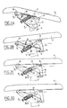
- fig. 1A, 1B, 1C show respective schematic side views of a chair according to the present invention in rearward tilted position, in the central position and in slightly forward tilted position;
- fig. 2A-2D show respective schematic side views of the tilting of the seat of the chair shown in fig. 1A-1C with respective different weight adjustments;
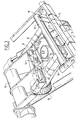
- fig. 3 is a top view in perspective of the tilting means of fig. 2A-2D of the chair according to the present invention;
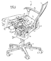
- fig. 4 is a view in perspective of the chair according to the present invention shown in fig. 1A-3; and
- fig. 5 is a view in perspective of detail V of fig. 4.
- A chair 1 (fig. 1A, 1B, 1C and 4) comprises an support frame 2 provided with a plurality of
wheels 3 which are connected viaside legs 4 to acentral leg 5 which is height-adjustable using a gas spring and relative to which aseat 6 can rotate. Achair back 7 is connected toseat 6 viaarms 8. - As shown clearly in fig. lA-lC, a
pivot shaft 10 is situated at about a third the way along from the front edge ofseat 6. Fig. 1A shows the position in whichseat 6 andchair back 7 are tilted slightly rearward relative topivot shaft 10, wherein due to the position of pivot shaft 10 a user is prevented, while retaining a hollow back, from banging his knees against the underside of a work surface or his/her feet leaving the floor. The position shown in fig. 1A is used for instance during consultations and meetings. In the position shown in fig. lB, which is for instance suitable for work at a monitor, chair back and seat are tilted less far to the rear than in fig. lA, while the user automatically retains a correct ergonomic posture with hollow back. The position of the tilt of the seat and chair back is determined by the desired viewing direction, i.e roughly 70° relative to the activities to be performed. In the position shown in fig. 1C, which is particularly suitable for reading and writing, the user therefore has the tendency to bend further forward. In this position the seat is tilted forward at a small angle in order to ensure that the user retains a hollow back and wherein the position ofpivot shaft 10 prevents an inclination of the seat being reached such that the user will have to provide strong opposing force to prevent him/her sliding forward. - As also shown clearly in fig. 1A-1C, the chair is preferably provided with arm rests which are disposed fixedly relative to a rotatable leg part and preferably take a form such that they abut well against a table top T (after being set at the correct height by the user) and which form follows the ergonomically correct position of the elbows during rearward tilting of the seat together with the chair back as well as during forward and rearward adjusting of the chair back relative to the seat. The arched shape follows approximately an arc of a circle relative to
pivot shaft 10, wherein a portion abutting the table top is preferably slightly flat in order to properly abut thereagainst. Because the arm rests do not move together with the tilting movement, the fingers of the user are also prevented from possibly being caught between table top and arm rests. - In the position of
seat 6 shown in fig. 2A, which corresponds with the position in fig. 1A, wherein at least the rear part ofseat 6 is tilted to the rear through an angle of for instance about 10° to 15° or 17°, agas spring 11 is arranged between afirst pivot point 12 and asecond pivot point 13, wherein the second pivot point is arranged on apivotable arm 14.Gas spring 11 is situated at an acute angle α relative to the horizontal.Arm 14 is fixedly connected viarotatable sleeve 35 to guidearms 36 and 37 (see also fig. 3, 4 and 5) in which the respective shafts ends 30 and 31 are guided. Shaft ends 30 and 31 protrude throughrespective slots component 34 which is arranged on a sleeveround pivot shaft 10, this sleeve forming part of the seat frame. - When seat 6 (at least the rear part thereof) is caused to move upward from the position shown in fig. 2A, for instance because the individual stands up, it is pressed upward by
gas spring 11 viaarm 14 and guidearms sleeve 15 than in the position shown in fig. 2A and the direction of the force exerted by the gas spring makes a smaller angle relative toarm 14, the moment applied toseat 6 bygas spring 11 is less in the position shown in fig. 2B than in the position shown in fig. 2A. The angle α' in fig. 2B is moreover smaller than angle a. The progressive action of the gas spring is however obtained mainly by the change in lever length ofguide arms arm 14. The moment onseat 6 therefore increases progressively during backward tilting of at least the rear portion ofseat 6. An even upward movement ofseat part 6 thus takes place while during the reverse movement, i.e. backward tilting, an increasing opposing force is exerted. - For instance in the horizontal position of
seat part 6 as shown in fig. 2C and 2D, the position of shaft ends 30, 31 (see below in respect of fig. 3) is determined by the position of a weight adjustingscrew knob 16, wherein in the extreme position shown in fig. 2D the moment applied bygas spring 11 is smaller during tilting and more suitable for a light person than in the extreme position shown in fig. 2C which is more suitable for a heavy person. - The
gas spring 11 is preferably a gas spring which is lockable in continuously variable manner in any position, wherein use is made of non-compressible medium, for instance a liquid, which is incorporated therein. - Fig. 3 further shows that by turning
knob 16 shaft ends orrollers 30 respectively 31 can be displaced in theguide arms rotatable sleeve 35 on which thearm 14 on whichgas spring 11 engages is also fixedly arranged. - For instance in the horizontal position of the seat, the position of
arms pins 30 respectively 31 are guided is not changed by rotating the turningknob 16 preferably arranged centrally under the seat, and the position of thearm 14 is thus not changed either viasleeve 35, andgas spring 11 is therefore not set longer or shorter. This adjustment can therefore take place using very little energy. This is an important advantage of the chair according to the present invention when compared to existing weight adjusting systems, wherein the force of a helical spring geared to the weight of a user must usually be adjusted, and much manual force is required for this purpose. - In order to further decrease the resistance, one or more rotatable shafts or other components can be provided with needle bearings (or ball bearings).
- Due to the weight adjustment the change in the length of the lever defined by
arm 14 and guidearms - Fig. 4 and 5 show a
further gas spring 40 which engages on a pivot shaft 41 on whicharms 8 of chair back 7 are pivotally mounted.Handles 42 operate ancontrol mechanism 43 forgas spring 40 and are situated on either side ofseat 6 at a natural position for adjusting the chair back 7, i.e. close to outer ends ofarms 8.Handles 44 extend roughly in the middle ofseat 6 on either side thereunder for operation of acontrol mechanism 49 of the gas spring (not shown) incentral leg 5. Control levers 45 are situated close to the front side of the seat to bring about operation viarod 46 ofcontrol mechanisms 47 for the tilting (gas spring 11). - With
control knobs 48 both arm rests 20 can be adjusted away from and toward each other, while in a manner not further shown they are both height-adjustable and detachable. - In a manner not shown the cushions for the seat and the chair back are arranged in a preferred embodiment against a plastic shell part and the cushions can be snapped into place thereon so that different colours can be arranged and for instance a low or high cushion can be arranged for the chair back. The seat cushion for instance can also be displaced for forward and backward adjustment in order to set the so-called sitting depth, while the chair back cushion is preferably likewise movable for height adjustment together with the shell onto which it is snapped in place.
- The seat cushion must be embodied such that it must be able to follow the positions shown in fig. lA-lC, i.e. either be of soft and flexible material such that the movements imposed by
pivot shaft 10 can be followed, or take a divided form with an internal pivotable construction with extremely soft flexible material at the position of the pivot shaft. - As shown particularly clearly in fig. 4 and 5, the
arms 8 extend beyond and below the rear edge of the seat, thereby further preventing that during rearward adjustment of the chair back the lower part thereof is displaced relative to the lower part of the back of the user and the correct ergonomic position is preserved and the user does not acquire a tendency to curve his/her back outward. - The present invention is in no way limited to the above described preferred embodiment thereof. The rights requested are defined by the following claims, within the scope of which many modifications are conceivable.
- A non-limitative modification relates to a seat of which the front part is movable between a horizontal position and a slightly forward inclined position (up to about 4° relative to the horizontal), while in the above described preferred embodiment, with an eye to cost, the provisional starting point is a fixed, slightly forward inclining front seat part.
Claims (18)
- Chair, comprising:- one or more leg parts;- a seat part which is arranged on the leg parts and which is tiltable both forward and backward; and- a chair back part which is adjustably connected to the seat part and which is tiltable together with this seat part, wherein tilting means for tilting at least a part of the seat part together with the chair back part engage at a location under the seat part which is situated further forward than the centre of the seat part and wherein the tilting means comprise at least one gas spring member which is arranged in lying position under the seat part such that when the seat part and the chair back part are tilted to the rear the opposing force exerted by the gas spring member increases.
- Chair as claimed in claim 1, wherein the location is situated at about one third the length of the seat part.
- Chair as claimed in claim 1 or 2, wherein the tilting means comprise a gas spring extending at a relatively small angle relative to the horizontal.
- Chair as claimed in claim 3, wherein the gas spring is lockable in continuously variable position.
- Chair as claimed in any of the foregoing claims, wherein the tilting means comprise weight adjusting means for the gas spring.
- Chair as claimed in claim 5, wherein the weight adjusting means are suitable for displacing a point of engagement of the force of the gas spring member.
- Chair as claimed in any of the foregoing claims, wherein the seat part comprises two portions which are at least slightly movable relative to each other.
- Chair as claimed in any of the claims 1-7, provided with arm rest parts coupled fixedly to a leg part rotatable on the vertical shaft.
- Chair as claimed in claim 8, wherein the tilting means comprise weight adjusting means.
- Chair as claimed in any of the claims 1-9, wherein adjusting means for adjusting the chair back engage on a pivot shaft which extends close to the underside of the seat part at a distance from the rear edge thereof.
- Chair as claimed in any of the foregoing claims, wherein a central leg part is height-adjustable.
- Chair as claimed in any of the foregoing claims, wherein the seat part comprises a seat cushion of relatively soft material which is slidable for adjustment in forward and backward direction.
- Chair as claimed in claim 12, wherein the chair back part comprises a chair back cushion of relatively soft material which is slidable for height adjustment.
- Chair as claimed in any of the foregoing claims, wherein cushions for the seat part and/or the chair back part are can be fixed releasably using snap means.
- Chair as claimed in any of the foregoing claims, wherein the control lever for the tilting extends under the seat part substantially horizontally in the vicinity of the pivot shaft for this tilting.
- Chair as claimed in any of the foregoing claims, wherein a control lever for adjusting the position of the chair back relative to the seat extends under the seat part in the vicinity of the pivot shaft for this adjustment.
- Chair as claimed in any of the foregoing claims, wherein a control lever for height adjustment of the seat part extends roughly in the middle under the seat.
- Chair as claimed in claim 16, 17 or 18, wherein
the or each control lever extends under the seat on either side thereof.
Applications Claiming Priority (2)
| Application Number | Priority Date | Filing Date | Title |
|---|---|---|---|
| NL1002523 | 1996-03-04 | ||
| NL1002523A NL1002523C2 (en) | 1996-03-04 | 1996-03-04 | Tilting office chair. |
Publications (2)
| Publication Number | Publication Date |
|---|---|
| EP0793929A1 true EP0793929A1 (en) | 1997-09-10 |
| EP0793929B1 EP0793929B1 (en) | 2003-06-25 |
Family
ID=19762436
Family Applications (1)
| Application Number | Title | Priority Date | Filing Date |
|---|---|---|---|
| EP97200574A Expired - Lifetime EP0793929B1 (en) | 1996-03-04 | 1997-02-27 | Adjustable office chair |
Country Status (5)
| Country | Link |
|---|---|
| EP (1) | EP0793929B1 (en) |
| AT (1) | ATE243446T1 (en) |
| DE (1) | DE69722986T2 (en) |
| DK (1) | DK0793929T3 (en) |
| NL (1) | NL1002523C2 (en) |
Cited By (3)
| Publication number | Priority date | Publication date | Assignee | Title |
|---|---|---|---|---|
| EP1192877A3 (en) * | 2000-09-28 | 2003-05-28 | Formway Furniture Limited | A reclinable chair |
| EP1378269A1 (en) * | 2002-06-11 | 2004-01-07 | Mario Salvioli | Gymnastic apparatus for exercising abdominal muscles |
| NL1025833C2 (en) | 2004-03-26 | 2005-10-03 | Bma Ergonomics B V | Seat with automatic backrest angle adjustment. |
Citations (3)
| Publication number | Priority date | Publication date | Assignee | Title |
|---|---|---|---|---|
| EP0263323A2 (en) * | 1986-10-07 | 1988-04-13 | Inaba Seisakusho Co., Ltd. | Sitting furniture |
| EP0309368A1 (en) * | 1987-09-22 | 1989-03-29 | Steelcase Strafor | Ergonomic chair |
| EP0678259A1 (en) * | 1994-04-21 | 1995-10-25 | Manufacturas Metalicas Jevit, S.A. | Self-balancing ergonomic armchair |
-
1996
- 1996-03-04 NL NL1002523A patent/NL1002523C2/en not_active IP Right Cessation
-
1997
- 1997-02-27 DK DK97200574T patent/DK0793929T3/en active
- 1997-02-27 AT AT97200574T patent/ATE243446T1/en active
- 1997-02-27 DE DE69722986T patent/DE69722986T2/en not_active Expired - Lifetime
- 1997-02-27 EP EP97200574A patent/EP0793929B1/en not_active Expired - Lifetime
Patent Citations (3)
| Publication number | Priority date | Publication date | Assignee | Title |
|---|---|---|---|---|
| EP0263323A2 (en) * | 1986-10-07 | 1988-04-13 | Inaba Seisakusho Co., Ltd. | Sitting furniture |
| EP0309368A1 (en) * | 1987-09-22 | 1989-03-29 | Steelcase Strafor | Ergonomic chair |
| EP0678259A1 (en) * | 1994-04-21 | 1995-10-25 | Manufacturas Metalicas Jevit, S.A. | Self-balancing ergonomic armchair |
Cited By (3)
| Publication number | Priority date | Publication date | Assignee | Title |
|---|---|---|---|---|
| EP1192877A3 (en) * | 2000-09-28 | 2003-05-28 | Formway Furniture Limited | A reclinable chair |
| EP1378269A1 (en) * | 2002-06-11 | 2004-01-07 | Mario Salvioli | Gymnastic apparatus for exercising abdominal muscles |
| NL1025833C2 (en) | 2004-03-26 | 2005-10-03 | Bma Ergonomics B V | Seat with automatic backrest angle adjustment. |
Also Published As
| Publication number | Publication date |
|---|---|
| DK0793929T3 (en) | 2003-10-13 |
| ATE243446T1 (en) | 2003-07-15 |
| DE69722986T2 (en) | 2004-06-09 |
| EP0793929B1 (en) | 2003-06-25 |
| DE69722986D1 (en) | 2003-07-31 |
| NL1002523C2 (en) | 1997-09-05 |
Similar Documents
| Publication | Publication Date | Title |
|---|---|---|
| US6189971B1 (en) | Task chair with adjustable seat depth | |
| US6752459B2 (en) | Adjustable chair | |
| EP0572504B1 (en) | Ergonomically improved chair or armchair | |
| US6644748B2 (en) | Synergistic body positioning and dynamic support system | |
| US8944507B2 (en) | Ergonomic adjustable chair mechanisms | |
| US9585478B1 (en) | Adjustable seating | |
| US5098160A (en) | Ergonomic seating system apparatus | |
| US20070063569A1 (en) | Two-position desk chair | |
| WO2009048448A1 (en) | Dynamically balanced seat assembly | |
| NO834685L (en) | FLEXIBLE CHAIR | |
| US20020142898A1 (en) | Office exercise furniture | |
| US20010020810A1 (en) | Computer work station | |
| US11246417B2 (en) | Tilt-swivel mechanism chair | |
| US6196631B1 (en) | Ergonomic footrests for ergonomic chairs | |
| GB2176396A (en) | Posture support chair | |
| EP0793929B1 (en) | Adjustable office chair | |
| EP1579787A1 (en) | Chair having automatic back inclination adjustment | |
| US20220330700A1 (en) | Chair having tilting seat and back | |
| WO2014021796A1 (en) | Adjustable support structure | |
| US20200297120A1 (en) | Half-sitting stool with supported sit bone | |
| DK176630B1 (en) | Ergonomic chair | |
| KR200295381Y1 (en) | A chair of controling angle of inclination | |
| EP0672370B1 (en) | Chair having an assisted scissor mechanism | |
| CN213962528U (en) | Novel sofa gear shifting chair | |
| EP2130457B1 (en) | Chair |
Legal Events
| Date | Code | Title | Description |
|---|---|---|---|
| PUAI | Public reference made under article 153(3) epc to a published international application that has entered the european phase |
Free format text: ORIGINAL CODE: 0009012 |
|
| AK | Designated contracting states |
Kind code of ref document: A1 Designated state(s): AT BE CH DE DK FI FR GB IE LI LU NL SE |
|
| AX | Request for extension of the european patent |
Free format text: LT;LV;RO;SI |
|
| 17P | Request for examination filed |
Effective date: 19980303 |
|
| RBV | Designated contracting states (corrected) |
Designated state(s): AT BE CH DE DK FI FR GB IE LI LU NL SE |
|
| 17Q | First examination report despatched |
Effective date: 20020220 |
|
| GRAH | Despatch of communication of intention to grant a patent |
Free format text: ORIGINAL CODE: EPIDOS IGRA |
|
| GRAH | Despatch of communication of intention to grant a patent |
Free format text: ORIGINAL CODE: EPIDOS IGRA |
|
| GRAA | (expected) grant |
Free format text: ORIGINAL CODE: 0009210 |
|
| AK | Designated contracting states |
Designated state(s): AT BE CH DE DK FI FR GB IE LI LU NL SE |
|
| DAX | Request for extension of the european patent (deleted) | ||
| REG | Reference to a national code |
Ref country code: GB Ref legal event code: FG4D |
|
| REG | Reference to a national code |
Ref country code: CH Ref legal event code: EP |
|
| REG | Reference to a national code |
Ref country code: CH Ref legal event code: NV Representative=s name: ARNOLD & SIEDSMA AG |
|
| REG | Reference to a national code |
Ref country code: SE Ref legal event code: TRGR |
|
| REG | Reference to a national code |
Ref country code: IE Ref legal event code: FG4D |
|
| REF | Corresponds to: |
Ref document number: 69722986 Country of ref document: DE Date of ref document: 20030731 Kind code of ref document: P |
|
| PLBE | No opposition filed within time limit |
Free format text: ORIGINAL CODE: 0009261 |
|
| STAA | Information on the status of an ep patent application or granted ep patent |
Free format text: STATUS: NO OPPOSITION FILED WITHIN TIME LIMIT |
|
| ET | Fr: translation filed | ||
| 26N | No opposition filed |
Effective date: 20040326 |
|
| REG | Reference to a national code |
Ref country code: FR Ref legal event code: PLFP Year of fee payment: 20 |
|
| PGFP | Annual fee paid to national office [announced via postgrant information from national office to epo] |
Ref country code: LU Payment date: 20160224 Year of fee payment: 20 |
|
| PGFP | Annual fee paid to national office [announced via postgrant information from national office to epo] |
Ref country code: CH Payment date: 20160226 Year of fee payment: 20 Ref country code: IE Payment date: 20160224 Year of fee payment: 20 Ref country code: DK Payment date: 20160229 Year of fee payment: 20 Ref country code: DE Payment date: 20160224 Year of fee payment: 20 |
|
| PGFP | Annual fee paid to national office [announced via postgrant information from national office to epo] |
Ref country code: GB Payment date: 20160229 Year of fee payment: 20 Ref country code: BE Payment date: 20160224 Year of fee payment: 20 Ref country code: SE Payment date: 20160229 Year of fee payment: 20 Ref country code: NL Payment date: 20160224 Year of fee payment: 20 Ref country code: FR Payment date: 20160226 Year of fee payment: 20 Ref country code: FI Payment date: 20160224 Year of fee payment: 20 Ref country code: AT Payment date: 20160225 Year of fee payment: 20 |
|
| REG | Reference to a national code |
Ref country code: DE Ref legal event code: R082 Ref document number: 69722986 Country of ref document: DE Representative=s name: ARNOLD & SIEDSMA, DE Ref country code: DE Ref legal event code: R082 Ref document number: 69722986 Country of ref document: DE Representative=s name: ARNOLD UND KOLLEGEN, DE Ref country code: DE Ref legal event code: R081 Ref document number: 69722986 Country of ref document: DE Owner name: SCANDINAVIAN BUSINESS SEATING B.V., NL Free format text: FORMER OWNER: RUDIMEC B.V., HARDENBERG, NL |
|
| REG | Reference to a national code |
Ref country code: CH Ref legal event code: PUE Owner name: SCANDINAVIAN BUSINESS SEATING B.V., NL Free format text: FORMER OWNER: RUDIMEC B.V., NL Ref country code: CH Ref legal event code: NV Representative=s name: ARNOLD AND SIEDSMA AG, CH |
|
| REG | Reference to a national code |
Ref country code: NL Ref legal event code: PD Owner name: SCANDINAVIAN BUSINESS SEATING B.V.; NL Free format text: DETAILS ASSIGNMENT: VERANDERING VAN EIGENAAR(S), OVERDRACHT; FORMER OWNER NAME: RUDIMEC B.V. Effective date: 20160905 |
|
| REG | Reference to a national code |
Ref country code: DE Ref legal event code: R082 Ref document number: 69722986 Country of ref document: DE Representative=s name: ARNOLD & SIEDSMA, DE Ref country code: DE Ref legal event code: R081 Ref document number: 69722986 Country of ref document: DE Owner name: SCANDINAVIAN BUSINESS SEATING B.V., NL Free format text: FORMER OWNER: SKANDINAVIAN BUSINESS SEATING B.V., ETTEN-LEUR, NL |
|
| REG | Reference to a national code |
Ref country code: FR Ref legal event code: TP Owner name: SCANDINAVIAN BUSINESS SEATING B.V., NL Effective date: 20160907 |
|
| REG | Reference to a national code |
Ref country code: GB Ref legal event code: 732E Free format text: REGISTERED BETWEEN 20161020 AND 20161026 |
|
| REG | Reference to a national code |
Ref country code: AT Ref legal event code: PC Ref document number: 243446 Country of ref document: AT Kind code of ref document: T Owner name: SCANDINAVIAN BUSINESS SEATING B.V., NL Effective date: 20161129 |
|
| REG | Reference to a national code |
Ref country code: DE Ref legal event code: R071 Ref document number: 69722986 Country of ref document: DE |
|
| REG | Reference to a national code |
Ref country code: NL Ref legal event code: MK Effective date: 20170226 |
|
| REG | Reference to a national code |
Ref country code: DK Ref legal event code: EUP Effective date: 20170227 |
|
| REG | Reference to a national code |
Ref country code: CH Ref legal event code: PL |
|
| REG | Reference to a national code |
Ref country code: GB Ref legal event code: PE20 Expiry date: 20170226 Ref country code: IE Ref legal event code: MK9A |
|
| REG | Reference to a national code |
Ref country code: SE Ref legal event code: EUG |
|
| REG | Reference to a national code |
Ref country code: AT Ref legal event code: MK07 Ref document number: 243446 Country of ref document: AT Kind code of ref document: T Effective date: 20170227 |
|
| PG25 | Lapsed in a contracting state [announced via postgrant information from national office to epo] |
Ref country code: GB Free format text: LAPSE BECAUSE OF EXPIRATION OF PROTECTION Effective date: 20170226 Ref country code: IE Free format text: LAPSE BECAUSE OF EXPIRATION OF PROTECTION Effective date: 20170227 |