EP0793053B1 - Vorrichtung für die Beseitigung von Flüssigkeiten und/oder Verunreinigungen aus einem Gas - Google Patents
Vorrichtung für die Beseitigung von Flüssigkeiten und/oder Verunreinigungen aus einem Gas Download PDFInfo
- Publication number
- EP0793053B1 EP0793053B1 EP97200436A EP97200436A EP0793053B1 EP 0793053 B1 EP0793053 B1 EP 0793053B1 EP 97200436 A EP97200436 A EP 97200436A EP 97200436 A EP97200436 A EP 97200436A EP 0793053 B1 EP0793053 B1 EP 0793053B1
- Authority
- EP
- European Patent Office
- Prior art keywords
- recipient
- space
- float
- gas
- impurities
- Prior art date
- Legal status (The legal status is an assumption and is not a legal conclusion. Google has not performed a legal analysis and makes no representation as to the accuracy of the status listed.)
- Expired - Lifetime
Links
- 239000007788 liquid Substances 0.000 title claims description 27
- 239000012535 impurity Substances 0.000 title claims description 16
- 239000012528 membrane Substances 0.000 claims description 4
- 125000006850 spacer group Chemical group 0.000 claims description 4
- 238000007789 sealing Methods 0.000 description 3
- 238000004378 air conditioning Methods 0.000 description 1
- 230000004075 alteration Effects 0.000 description 1
- 238000012423 maintenance Methods 0.000 description 1
- 238000005192 partition Methods 0.000 description 1
Images


Classifications
-
- F—MECHANICAL ENGINEERING; LIGHTING; HEATING; WEAPONS; BLASTING
- F16—ENGINEERING ELEMENTS AND UNITS; GENERAL MEASURES FOR PRODUCING AND MAINTAINING EFFECTIVE FUNCTIONING OF MACHINES OR INSTALLATIONS; THERMAL INSULATION IN GENERAL
- F16T—STEAM TRAPS OR LIKE APPARATUS FOR DRAINING-OFF LIQUIDS FROM ENCLOSURES PREDOMINANTLY CONTAINING GASES OR VAPOURS
- F16T1/00—Steam traps or like apparatus for draining-off liquids from enclosures predominantly containing gases or vapours, e.g. gas lines, steam lines, containers
- F16T1/20—Steam traps or like apparatus for draining-off liquids from enclosures predominantly containing gases or vapours, e.g. gas lines, steam lines, containers with valves controlled by floats
- F16T1/22—Steam traps or like apparatus for draining-off liquids from enclosures predominantly containing gases or vapours, e.g. gas lines, steam lines, containers with valves controlled by floats of closed-hollow-body type
Definitions
- the present invention relates to a device for the removal of liquids and/or impurities from a gas, comprising a first recipient, which at its upper end communicates with a space or conduit in which gas is contained and a float, commanding a valve opening or closing an outlet, respectively.
- the invention is mainly applied in devices such as compressors, dry air blowers, air-conditioning systems and the like, with a view to regulate the percentage of humidity which is present in the air.
- the known devices make use of a recipient that catches the humidity from the gas, whereby these devices are provided with a float that co-operates with a valve that opens an outlet at the bottom of the said recipient when the level of the liquid reaches a certain height in the recipient in order to drain in that way periodically the liquid and/or the impurities.
- the outlet in the recipient must have a smaller diameter in order that the drainage of the liquid occurs slowly so that no transitional phenomena arise in the characteristics of the gas, such as alterations in pressure or volume.
- a serious disadvantage of these known devices is the fact that impurities that are present in the gas, will sink to the bottom of the above-mentioned recipient, whereby they can easily obstruct the small outlet in the recipient when the valve opens, which results in a poor operation of the device and can even render it inoperative.
- the present invention aims at excluding the abovementioned and other disadvantages.
- a second recipient is located within the first recipient and is substantially closed off from the gas space or conduit, and a connecting canal is provided in a space between both recipients and having a bottom end communicating with said space and an upper end debouching through a passage into the second recipient, the float being inside the second recipient.
- Such device is described in the FR 354.458.
- This device consists of two adjacent recipients, the first one being in communication with the second one by means of an overflow. The dirt is collected in the first recipient, while the second recipient is provided with a valve controlled by a float.
- This device comprises a collecting vessel, wherein a float is arranged on an riser tube passing through the float.
- a discharge pipe is arranged coaxially in the riser tube with a space in between.
- the top end of the riser tube is closed by a sealing element associated with the top end of the discharge pipe.
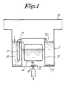
- the device according to the invention mainly consists of a recipient 1 which communicates at its upper end with the space or the conduit 2 in which the gas is contained, from which liquid and/or impurities must be removed.
- a second recipient 3 is applied in which is situated a float 4 that commands a valve 5 which can respectively close and open an outlet 6.
- a vertical connecting canal 7 is applied which communicates at its bottom with the space 8 between both recipients and debouches at its upper end into the recipient 3.
- the recipient 3 At its upper end the recipient 3 is cut off from the space or conduit 2, possibly with the exception of a small ventilating opening 10 which is positioned at a level which is higher than the passage 9 and which, in this embodiment, is directed downwards.
- the operation of the device is simple and as follows.
- Humidity in the gas will be caught in the recipient 1 on account of its higher weight with regard to the gas.
- the level of liquid in the space 8 and in the connecting canal 7 will evenly rise.
- the valve 5 will remain in its normal closed position on account of the weight of the float 4.
- Liquid will now drain through the small drainage opening 6 from the recipient 3, by which the level of the liquid and at the same time the float 4 in the recipient 3 will drop until the float 4 automatically closes the valve 5 again.
- Impurities 11 from the gas will never be propelled upwards jointly with the liquid in the connecting canal 7 on account of their weight. As a result the content of the recipient will always remain free from impurities, whereby obstructions of the outlet 6 are avoided.
- the recipient 3 is formed by a tubular case 12 across which a dome 13 is applied which is fastened at a certain distance with regard to the tubular case 12 by means of spacers 14.
- spacers 14 could possibly extend as far as against or almost against the inner wall of the recipient 1 in such a manner that partitions are formed which counteract possible turbulences in the column of the liquid.
- the connecting canal 7 is formed by the space between the tubular case 12 and the dome 13.
- the tubular case 12 narrows downwards into a throat 15 which protrudes through an opening 16 at the bottom of the recipient 1 and which is fixed to the recipient 1 by means of a nut 17.
- a sealing ring 19 is applied between the collar 18 of the tubular case 12 and the opening 16 in the recipient 1.
- the valve is preferably formed by an elastic membrane 20 which is fixed to a protrusion 21 of the float 4, on the one hand, and to a protrusion 22 in the recipient 3, on the other hand.
- the membrane 20 is for example provided with openings 23-24 which allow to apply it over the protrusions 21-22 and to keep it there by means of tightening rings 25-26.
- valve seat 27 which is fixedly attached in the collar 18 of the tubular case 12 is provided with a small opening which forms the outlet 6 of the device. This outlet 6 debouches downstream in the outlet canal 28 which itself extends outside the device.
- the dome 13 is at the upper end closed with the exception of a downward directed small ventilating opening 10 which is situated at a height which is higher than the passage 9.
- the ventilating opening 10 is directed downwards in order to avoid that impurities from the gas would arrive along this opening into the recipient 3.
- the recipient 1 is provided with an extra opening 29 which can be closed by means of a tap 30.
- impurities 11 on the bottom of the recipient 1 can be drained in order to avoid that the their quantity increases in the recipient 1 in such a manner that they would arrive through the connecting canal 7 into the recipient 3, whereby they would obstruct the outlet 6.
- the device is very effective and simple in operation and maintenance.
Landscapes
- Engineering & Computer Science (AREA)
- General Engineering & Computer Science (AREA)
- Mechanical Engineering (AREA)
- Separating Particles In Gases By Inertia (AREA)
- Float Valves (AREA)
- Self-Closing Valves And Venting Or Aerating Valves (AREA)
- Pipeline Systems (AREA)
- Drying Of Gases (AREA)
- Sampling And Sample Adjustment (AREA)
Claims (9)
- Vorrichtung für die Beseitung von Flüssigkeiten und/oder Verunreinigungen aus einem Gas, umfassend einen ersten Behälter (1), der an seinem oberen Ende mit einem Raum oder einer Leitung (2) in Verbindung steht, worin Gas enthalten ist, und einen Schwimmer (4), der ein Ventil (5) steuert, das einen Auslass (6) geschlossen hält, beziehungsweise ihn öffnet, gekennzeichnet durch einen zweiten Behälter (3), der sich in dem ersten Behälter (1) befindet und hauptsächlich vom Gasraum oder der Gasleitung (2) abgeschlossen ist, und einen Kanal (7), der in einem Raum (8) zwischen den beiden Behältern (1-3) vorgesehen ist und ein unteres Ende aufweist, das mit besagtem Raum (8) in Verbindung steht, und ein oberes Ende, das durch einen Durchlass (9) im zweiten Behälter (3) mündet, wobei der Schwimmer (4) sich innerhalb des zweiten Behälters (3) befindet.
- Vorrichtung gemäß Anspruch 1, dadurch gekennzeichnet, dass der zweite Behälter (3) von einem röhrenförmigen Gehäuse (12) gebildet wird, über dem eine Kuppel (13) angebracht ist, die am oberen Ende abgeschlossen ist.
- Vorrichtung gemäß Anspruch 1 und 2, dadurch gekennzeichnet, dass der Verbindungskanal (7) von dem Raum zwischen dem röhrenförmigen Gehäuse (12) und der Kuppel (13) gebildet wird.
- Vorrichtung gemäß einem der vorgenannten Ansprüche, dadurch gekennzeichnet, dass das Ventil (5) von einer elastischen Membran (20) gebildet wird, die einerseits am Schwimmer (4) und andererseits am Behälter (3) befestigt ist.
- Vorrichtung gemäß Anspruch 4, dadurch gekennzeichnet, dass die elastische Membran (20) mit Öffnungen (23-24) versehen ist, um über Vorsprüngen (21-22) des Schwimmers (4) beziehungsweise des Behälters (3) angebracht zu werden, und die mittels Spannringen (25-26) befestigt werden.
- Vorrichtung gemäß einem der vorgenannten Ansprüche, dadurch gekennzeichnet, dass der Behälter (3) mit einer nach unten gerichteten Lüftungsöffnung (10) vresehen ist, die höher als der Durchlass (9) angeordnet ist.
- Vorrichtung gemäß einem der vorgenannten Ansprüche, dadurch gekennzeichnet, dass der Behälter (1) an seinem Boden mit einer Öffnung (29) versehen ist, die normalerweise mit einem Stopfen (30) verschlossen ist.
- Vorrichtung gemäß Anspruch 2 oder 3, dadurch gekennzeichnet, dass in dem Raum zwischen dem röhrenförmigen Gehäuse (12) und der Kuppel (13) Zwischenstücke (14) vorgesehen sind.
- Vorrichtung gemäß Anspruch 8, dadurch gekennzeichnet, dass die Zwischenstücke (14) sich bis gegen oder nahezu gegen die Innenwand des Behälters (1) erstrecken.
Applications Claiming Priority (2)
| Application Number | Priority Date | Filing Date | Title |
|---|---|---|---|
| BE9600178 | 1996-02-29 | ||
| BE9600178A BE1010051A3 (nl) | 1996-02-29 | 1996-02-29 | Inrichting voor het verwijderen van vloeistoffen en/of onreinheden uit een gas. |
Publications (2)
| Publication Number | Publication Date |
|---|---|
| EP0793053A1 EP0793053A1 (de) | 1997-09-03 |
| EP0793053B1 true EP0793053B1 (de) | 2000-12-06 |
Family
ID=3889575
Family Applications (1)
| Application Number | Title | Priority Date | Filing Date |
|---|---|---|---|
| EP97200436A Expired - Lifetime EP0793053B1 (de) | 1996-02-29 | 1997-02-14 | Vorrichtung für die Beseitigung von Flüssigkeiten und/oder Verunreinigungen aus einem Gas |
Country Status (7)
| Country | Link |
|---|---|
| US (1) | US5769911A (de) |
| EP (1) | EP0793053B1 (de) |
| JP (1) | JPH09313863A (de) |
| BE (1) | BE1010051A3 (de) |
| DE (1) | DE69703630T2 (de) |
| DK (1) | DK0793053T3 (de) |
| ES (1) | ES2154011T3 (de) |
Families Citing this family (9)
| Publication number | Priority date | Publication date | Assignee | Title |
|---|---|---|---|---|
| DE29718851U1 (de) | 1997-10-23 | 1997-12-11 | Festo AG & Co, 73734 Esslingen | Flüssigkeitsablaß |
| DE10239408A1 (de) * | 2002-08-28 | 2004-03-11 | Robert Bosch Gmbh | Vorrichtung zur Abscheidung von Flüssigkeit aus einem Gasstrom |
| NL1026260C2 (nl) * | 2004-05-25 | 2005-11-28 | Nefit Buderus B V | Afsluiter voor een vloeistofafvoer, samenstel hiervan met een condensopvangbak. |
| NL2015487B1 (en) * | 2015-09-22 | 2017-04-20 | Remeha B V | A condensate collection and discharge unit. |
| USD838811S1 (en) | 2016-08-12 | 2019-01-22 | Control Devices, Llc | Automatic drain valve |
| US10018301B2 (en) | 2016-08-12 | 2018-07-10 | Control Devices, Llc | Drain valve |
| US10197184B2 (en) | 2016-08-12 | 2019-02-05 | Control Devices, Llc | Float |
| US10295075B2 (en) | 2017-01-10 | 2019-05-21 | Control Devices, Llc | Cylinder valve |
| KR102398052B1 (ko) * | 2019-05-03 | 2022-05-16 | 주식회사 경동나비엔 | 응축수 트랩장치 |
Family Cites Families (13)
| Publication number | Priority date | Publication date | Assignee | Title |
|---|---|---|---|---|
| US381150A (en) * | 1888-04-17 | Separator | ||
| FR354458A (fr) * | 1905-04-18 | 1905-10-06 | Alton Levi French | Appareil à flotteur pour régler le débit de la vapeur |
| US1255395A (en) * | 1916-05-05 | 1918-02-05 | Arthur E Duram | Liquid-separator and the like. |
| GB126963A (en) * | 1917-07-09 | 1919-09-25 | Alexandre Lobet | Improvements in Automatic Steam Traps. |
| US1448972A (en) * | 1920-07-06 | 1923-03-20 | John C F Long | Steam trap |
| US2311697A (en) * | 1938-08-31 | 1943-02-23 | Samiran David | Fluid segregating apparatus |
| US3112190A (en) * | 1959-06-26 | 1963-11-26 | Bowser Inc | Method and apparatus for decontaminating hydraulic fluids |
| US3130023A (en) * | 1962-04-24 | 1964-04-21 | William J Hasselberg | Gas- and air-moisture separator |
| US3378993A (en) * | 1963-07-03 | 1968-04-23 | Bastian Blessing Co | Air line filter |
| GB1472221A (en) * | 1974-06-18 | 1977-05-04 | Neuman Gmbh | Condensate draw-off units for dewatering gases |
| US3912629A (en) * | 1975-01-30 | 1975-10-14 | Fuji Kinzoku Kosaku Kabushiki | Automatic drain trap |
| US4136009A (en) * | 1977-11-17 | 1979-01-23 | David Samiran | Adjustable float and filter assembly |
| SE425691B (sv) * | 1981-03-26 | 1982-10-25 | Atlas Copco Ab | Dreneringsventilanordning |
-
1996
- 1996-02-29 BE BE9600178A patent/BE1010051A3/nl not_active IP Right Cessation
-
1997
- 1997-02-14 EP EP97200436A patent/EP0793053B1/de not_active Expired - Lifetime
- 1997-02-14 DE DE69703630T patent/DE69703630T2/de not_active Expired - Fee Related
- 1997-02-14 ES ES97200436T patent/ES2154011T3/es not_active Expired - Lifetime
- 1997-02-14 DK DK97200436T patent/DK0793053T3/da active
- 1997-02-25 US US08/805,294 patent/US5769911A/en not_active Expired - Fee Related
- 1997-02-27 JP JP9043174A patent/JPH09313863A/ja active Pending
Also Published As
| Publication number | Publication date |
|---|---|
| DE69703630D1 (de) | 2001-01-11 |
| DK0793053T3 (da) | 2001-03-19 |
| EP0793053A1 (de) | 1997-09-03 |
| JPH09313863A (ja) | 1997-12-09 |
| DE69703630T2 (de) | 2001-06-21 |
| US5769911A (en) | 1998-06-23 |
| ES2154011T3 (es) | 2001-03-16 |
| BE1010051A3 (nl) | 1997-12-02 |
Similar Documents
| Publication | Publication Date | Title |
|---|---|---|
| US6532988B1 (en) | Air admittance valve for sanitary waste pipe system | |
| US4212314A (en) | Waste water outlet sanitary plant comprising a siphon | |
| EP0793053A1 (de) | Vorrichtung für die Beseitigung von Flüssigkeiten und/oder Verunreinigungen aus einem Gas | |
| US11993454B2 (en) | Vent assembly | |
| US5088518A (en) | Steam restricter device | |
| US6092547A (en) | Double funnel float valve | |
| JP2008525674A (ja) | 衛生器具用の水トラップ | |
| US6745580B1 (en) | Combination P-trap, shutoff switch and cleanout fitting | |
| US9783972B2 (en) | Cistern for flushing a toilet with potable and gray water | |
| NL8403039A (nl) | Reduceerklep voorzien van een dampvloeistofscheider. | |
| EP0157437A2 (de) | Vorrichtung zum Be- oder Entlüften von durch eine Leitung strömenden Flüssigkeiten | |
| DK164300B (da) | Ventil, isaer til anvendelse i en sugeledning | |
| AU692835B2 (en) | A fluid diverter | |
| US20080041456A1 (en) | Air Vent | |
| US20120025123A1 (en) | High Capacity Air Admittance Valve for Sanitary Waste Pipe System | |
| CN208966320U (zh) | 一种石油伴生气输送管线用分液器 | |
| JP2003268755A (ja) | 自動給水装置 | |
| NO146842B (no) | Tyngdekraft-separator for ikke-blandbare vaesker | |
| CA1232563A (en) | Universal sanitary trap | |
| US700068A (en) | Feed-water cleaner. | |
| US3059666A (en) | Air filter | |
| WO1984003116A1 (en) | Level regulating bottom valve device for liquid receptacles | |
| US3130023A (en) | Gas- and air-moisture separator | |
| US1784943A (en) | Separator for light liquids | |
| EP0965074B1 (de) | Einrichtung zum regeln einer flüssigkeitsströmung |
Legal Events
| Date | Code | Title | Description |
|---|---|---|---|
| PUAI | Public reference made under article 153(3) epc to a published international application that has entered the european phase |
Free format text: ORIGINAL CODE: 0009012 |
|
| AK | Designated contracting states |
Kind code of ref document: A1 Designated state(s): CH DE DK ES FR GB IT LI NL SE |
|
| 17P | Request for examination filed |
Effective date: 19980227 |
|
| 17Q | First examination report despatched |
Effective date: 19991130 |
|
| GRAG | Despatch of communication of intention to grant |
Free format text: ORIGINAL CODE: EPIDOS AGRA |
|
| GRAG | Despatch of communication of intention to grant |
Free format text: ORIGINAL CODE: EPIDOS AGRA |
|
| GRAH | Despatch of communication of intention to grant a patent |
Free format text: ORIGINAL CODE: EPIDOS IGRA |
|
| GRAH | Despatch of communication of intention to grant a patent |
Free format text: ORIGINAL CODE: EPIDOS IGRA |
|
| GRAA | (expected) grant |
Free format text: ORIGINAL CODE: 0009210 |
|
| AK | Designated contracting states |
Kind code of ref document: B1 Designated state(s): CH DE DK ES FR GB IT LI NL SE |
|
| REG | Reference to a national code |
Ref country code: CH Ref legal event code: EP |
|
| REF | Corresponds to: |
Ref document number: 69703630 Country of ref document: DE Date of ref document: 20010111 |
|
| ITF | It: translation for a ep patent filed | ||
| REG | Reference to a national code |
Ref country code: CH Ref legal event code: NV Representative=s name: DIPL.-ING. ETH H. R. WERFFELI PATENTANWALT |
|
| ET | Fr: translation filed | ||
| REG | Reference to a national code |
Ref country code: ES Ref legal event code: FG2A Ref document number: 2154011 Country of ref document: ES Kind code of ref document: T3 |
|
| REG | Reference to a national code |
Ref country code: DK Ref legal event code: T3 |
|
| PLBE | No opposition filed within time limit |
Free format text: ORIGINAL CODE: 0009261 |
|
| STAA | Information on the status of an ep patent application or granted ep patent |
Free format text: STATUS: NO OPPOSITION FILED WITHIN TIME LIMIT |
|
| 26N | No opposition filed | ||
| REG | Reference to a national code |
Ref country code: GB Ref legal event code: IF02 |
|
| PGFP | Annual fee paid to national office [announced via postgrant information from national office to epo] |
Ref country code: SE Payment date: 20030128 Year of fee payment: 7 |
|
| PGFP | Annual fee paid to national office [announced via postgrant information from national office to epo] |
Ref country code: FR Payment date: 20030131 Year of fee payment: 7 |
|
| PGFP | Annual fee paid to national office [announced via postgrant information from national office to epo] |
Ref country code: GB Payment date: 20030211 Year of fee payment: 7 |
|
| PGFP | Annual fee paid to national office [announced via postgrant information from national office to epo] |
Ref country code: DK Payment date: 20030218 Year of fee payment: 7 |
|
| PGFP | Annual fee paid to national office [announced via postgrant information from national office to epo] |
Ref country code: NL Payment date: 20030226 Year of fee payment: 7 |
|
| PGFP | Annual fee paid to national office [announced via postgrant information from national office to epo] |
Ref country code: ES Payment date: 20030228 Year of fee payment: 7 |
|
| PGFP | Annual fee paid to national office [announced via postgrant information from national office to epo] |
Ref country code: DE Payment date: 20030410 Year of fee payment: 7 |
|
| PGFP | Annual fee paid to national office [announced via postgrant information from national office to epo] |
Ref country code: CH Payment date: 20030527 Year of fee payment: 7 |
|
| PG25 | Lapsed in a contracting state [announced via postgrant information from national office to epo] |
Ref country code: GB Free format text: LAPSE BECAUSE OF NON-PAYMENT OF DUE FEES Effective date: 20040214 |
|
| PG25 | Lapsed in a contracting state [announced via postgrant information from national office to epo] |
Ref country code: SE Free format text: LAPSE BECAUSE OF NON-PAYMENT OF DUE FEES Effective date: 20040215 |
|
| PG25 | Lapsed in a contracting state [announced via postgrant information from national office to epo] |
Ref country code: ES Free format text: LAPSE BECAUSE OF NON-PAYMENT OF DUE FEES Effective date: 20040216 |
|
| PG25 | Lapsed in a contracting state [announced via postgrant information from national office to epo] |
Ref country code: LI Free format text: LAPSE BECAUSE OF NON-PAYMENT OF DUE FEES Effective date: 20040229 Ref country code: CH Free format text: LAPSE BECAUSE OF NON-PAYMENT OF DUE FEES Effective date: 20040229 |
|
| PG25 | Lapsed in a contracting state [announced via postgrant information from national office to epo] |
Ref country code: DK Free format text: LAPSE BECAUSE OF NON-PAYMENT OF DUE FEES Effective date: 20040301 |
|
| PG25 | Lapsed in a contracting state [announced via postgrant information from national office to epo] |
Ref country code: NL Free format text: LAPSE BECAUSE OF NON-PAYMENT OF DUE FEES Effective date: 20040901 Ref country code: DE Free format text: LAPSE BECAUSE OF NON-PAYMENT OF DUE FEES Effective date: 20040901 |
|
| REG | Reference to a national code |
Ref country code: DK Ref legal event code: EBP |
|
| EUG | Se: european patent has lapsed | ||
| GBPC | Gb: european patent ceased through non-payment of renewal fee |
Effective date: 20040214 |
|
| REG | Reference to a national code |
Ref country code: CH Ref legal event code: PL |
|
| PG25 | Lapsed in a contracting state [announced via postgrant information from national office to epo] |
Ref country code: FR Free format text: LAPSE BECAUSE OF NON-PAYMENT OF DUE FEES Effective date: 20041029 |
|
| NLV4 | Nl: lapsed or anulled due to non-payment of the annual fee |
Effective date: 20040901 |
|
| REG | Reference to a national code |
Ref country code: FR Ref legal event code: ST |
|
| PG25 | Lapsed in a contracting state [announced via postgrant information from national office to epo] |
Ref country code: IT Free format text: LAPSE BECAUSE OF NON-PAYMENT OF DUE FEES Effective date: 20050214 |
|
| REG | Reference to a national code |
Ref country code: ES Ref legal event code: FD2A Effective date: 20040216 |