EP0792431B1 - Insulating jacket for hot and cold piping systems and the method of use - Google Patents
Insulating jacket for hot and cold piping systems and the method of use Download PDFInfo
- Publication number
- EP0792431B1 EP0792431B1 EP96917997A EP96917997A EP0792431B1 EP 0792431 B1 EP0792431 B1 EP 0792431B1 EP 96917997 A EP96917997 A EP 96917997A EP 96917997 A EP96917997 A EP 96917997A EP 0792431 B1 EP0792431 B1 EP 0792431B1
- Authority
- EP
- European Patent Office
- Prior art keywords
- jacket
- valve
- insulation
- halves
- valve jacket
- Prior art date
- Legal status (The legal status is an assumption and is not a legal conclusion. Google has not performed a legal analysis and makes no representation as to the accuracy of the status listed.)
- Expired - Lifetime
Links
Images


Classifications
-
- F—MECHANICAL ENGINEERING; LIGHTING; HEATING; WEAPONS; BLASTING
- F16—ENGINEERING ELEMENTS AND UNITS; GENERAL MEASURES FOR PRODUCING AND MAINTAINING EFFECTIVE FUNCTIONING OF MACHINES OR INSTALLATIONS; THERMAL INSULATION IN GENERAL
- F16L—PIPES; JOINTS OR FITTINGS FOR PIPES; SUPPORTS FOR PIPES, CABLES OR PROTECTIVE TUBING; MEANS FOR THERMAL INSULATION IN GENERAL
- F16L59/00—Thermal insulation in general
- F16L59/14—Arrangements for the insulation of pipes or pipe systems
- F16L59/16—Arrangements specially adapted to local requirements at flanges, junctions, valves or the like
- F16L59/161—Housings for valves, tee pieces, or the like
-
- Y—GENERAL TAGGING OF NEW TECHNOLOGICAL DEVELOPMENTS; GENERAL TAGGING OF CROSS-SECTIONAL TECHNOLOGIES SPANNING OVER SEVERAL SECTIONS OF THE IPC; TECHNICAL SUBJECTS COVERED BY FORMER USPC CROSS-REFERENCE ART COLLECTIONS [XRACs] AND DIGESTS
- Y10—TECHNICAL SUBJECTS COVERED BY FORMER USPC
- Y10T—TECHNICAL SUBJECTS COVERED BY FORMER US CLASSIFICATION
- Y10T137/00—Fluid handling
- Y10T137/0318—Processes
- Y10T137/0402—Cleaning, repairing, or assembling
-
- Y—GENERAL TAGGING OF NEW TECHNOLOGICAL DEVELOPMENTS; GENERAL TAGGING OF CROSS-SECTIONAL TECHNOLOGIES SPANNING OVER SEVERAL SECTIONS OF THE IPC; TECHNICAL SUBJECTS COVERED BY FORMER USPC CROSS-REFERENCE ART COLLECTIONS [XRACs] AND DIGESTS
- Y10—TECHNICAL SUBJECTS COVERED BY FORMER USPC
- Y10T—TECHNICAL SUBJECTS COVERED BY FORMER US CLASSIFICATION
- Y10T137/00—Fluid handling
- Y10T137/6851—With casing, support, protector or static constructional installations
- Y10T137/7036—Jacketed
-
- Y—GENERAL TAGGING OF NEW TECHNOLOGICAL DEVELOPMENTS; GENERAL TAGGING OF CROSS-SECTIONAL TECHNOLOGIES SPANNING OVER SEVERAL SECTIONS OF THE IPC; TECHNICAL SUBJECTS COVERED BY FORMER USPC CROSS-REFERENCE ART COLLECTIONS [XRACs] AND DIGESTS
- Y10—TECHNICAL SUBJECTS COVERED BY FORMER USPC
- Y10T—TECHNICAL SUBJECTS COVERED BY FORMER US CLASSIFICATION
- Y10T137/00—Fluid handling
- Y10T137/8158—With indicator, register, recorder, alarm or inspection means
- Y10T137/8359—Inspection means
Definitions
- the present invention is that of a multi-piece plastic removable and reusable insulation jacket for insulating valves for a hot or cold fluid piping system. More generally, this invention relates to an insulation cover for insulating any component in a fluid piping system including but not limited to valves, fittings, and pipe for temperatures of both below and above ambient.
- Pipe fittings shall include but not be limited to 90° elbows, 45° elbows, tees, wyes, unions, reducers, caps, clean outs, traps, strainers, pressure reducers, actuators, flanges, flow restrictors, metering devices, and elements.
- the most common and effective insulation applications of pipe, valves and fittings are for high (above ambient) temperature fluids.
- Differential temperatures in the majority of low temperature installations are on the order of 37.8°C (100°F) or less compared to high temperature installations where differentials exceeding 538°C (1000°F) are not uncommon with the majority of these installations having differentials between 93.3°C (200°F) and 371°C (700 °F).
- ambient humidity In high temperature piping applications ambient humidity is and remains in the vapor state, while in low temperature piping applications the ambient humidity or water vapor tends to condense or changes state from a vapor to a liquid or solid on the low temperature piping system surface.
- ambient water vapor molecules lose energy and concentrate in the boundary layer of the piping system surface.
- moisture begins to condense or freeze on the piping system surface and then cools to the surface temperature of the piping system.
- test results indicate that a series of concentric annuli can be used to provide insulating performance equal to or even exceeding the same thickness of fibrous insulation.
- the range of optimum air gap thicknesses is 0.63 cm to 0.13 cm (0.25 inches to 0.05 inches). However, at low temperature differentials between the pipe surface and the surroundings an air gap of larger than 1.27 cm (0.50 inches) can be effective.
- chilled liquid temperatures of around 1.7 °C (35°F) in the piping system and ambient temperatures of the surrounding atmosphere of around 100°F results in a temperature differential of around 18.3°C (65°F) and heat transfer in the form of heat gain by the chilled fluid in the piping system occurs primarily thou conduction and convection, with radiation heat transfer generally not being a significant factor. Under these conditions only one air gap or air space is normally required to provide the insulation characteristics necessary to effectively insulate the piping system.
- a radiantly reflective surface is employed preferably on the innermost interior surface of the insulating jackets to counter heat transfer due to radiation.
- Document EP 0 473 118 describes an insulating system which includes an air layer and the use of transparent material for inspection purposes. It has multiple jackets that enclose however only portions of a fluid element and cannot be easily installed and removed. There is therefore still a need for a single insulation system instead multiple insulation systems, which can be easily installed and removed and which insulates and inhibits condensation on all of the portions of the chilled fluid distribution element.
- the object of this invention is to provide an insulating valve jacket of thermoplastic for a valve in a chilled water system which can seal the valve off from the surrounding ambient environment thereby providing an effective vapor barrier to prevent the migration of moisture to the valve's cold surface and thus prevent the formation of condensation on the valve or insulation.
- an insulating jacket for a valve in a chilled water system which consists essentially of two identical thermoplastic sections to cover the valve body and a thermoplastic section to cover the valve handle which all interlock and seal together. Additionally, thermoplastic adaptor collars of identical pieces interlock, snap together and seal around and seal to the valve insulating jacket and the adjoining pipe insulation.
- this design concept could be applied to all kinds of pipe fittings, and the pipe of a chilled water system or other hot or cold fluid distribution systems.
- additional optimum air gaps could be built into the valve jacket wall to increase thermal efficiency and one or more of these air gaps could be evacuated to provide even more thermal efficiency.
- the air gap space could also be filled with any kind of insulation material to provide other insulation characteristics.
- this design concept could be used as a means to prevent pipe, valves, and fittings from freezing, either with or without heat tracing.
- a most significant object is to conserve energy in an efficient and cost effective manner.
- Another significant object is to utilize low permeability, clear, transparent or translucent, recycled or virgin thermoplastics to mold all the necessary valve jacket components.
- a plastic jacket for forming an insulation system of a chilled fluid distribution system element, an area of the jacket having a transparent or translucent portion so that the element or interior portions of the jacket can be inspected without removing the jacket, and forming a dead air space around the element (11, 12) wherein
- the insulation value of the dead air space is substantially all of the insulation value of the insulation system.
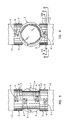
- FIG. 1 illustrates an installed valve jacket assembly complete with two valve jacket halves 1 and 1', valve handle cover 3, and two pairs of adapter collar halves 2 and 2' connecting the valve jacket halves 1 and 1' to the adjoining pipe insulation 13 covering pipes 11 on both sides of the valve 12 , showing all seven pieces of valve jacket assembly of which there are three different piece configurations 1 , 3 and 2 all in accordance with the preferred embodiments of the present application.
- this preferred embodiment could also be used for insulating any other type of pipe fitting including but not limited to 90° elbows, 45° elbows, tees, wyes, unions, reducers, caps, clean outs, or any other pipe line components including but not limited to traps, strainers, pressure reducers, actuators, flanges, flow restrictors, metering devices, and including but not limited to pipe, and other elements of well known nature. From the following detailed description, the manner of adapting the invention to these other conditions will be readily apparent to those skilled in the art.
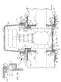
- FIG. 2 is an exploded perspective view of FIG. 1 with only four of the seven pieces shown, for clarity, that make up the valve jacket assembly of FIG. 1.
- the preferred embodiment of the valve jacket halves 1 and 1' that encloses valve 12 is that of two identical halves 1. Another less preferred embodiment is where two valve jacket pieces would be different in configuration.
- the two identical valve jacket halves 1 and 1' or the two valve jacket halves each of a different configuration could be connected together by a feature like but not limited to a live hinge as shown in FIG. 12 molded integral with the two parts, for example along the bottom edge, rendering the identical 1 and 1' or different configuration valve jacket pieces as a single component.
- valve jacket halves 1 and 1' when assembled together surrounding valve 12 are located and held in position straddling valve 12 by contact of cylindrical surfaces 7 of valve jacket halves 1 and 1' against pipes 11 on each side of valve 12.
- the cylindrical surfaces 7 must seal against pipes 11 to provide a barrier against the migration of water vapor across this interface. This seal can be accomplished many different ways including but not limited to providing a caulking material on this interface, a gasket material, or an "O" ring in an appropriate groove, not shown, in the cylindrical surface 7 of the valve jacket halves 1 and 1', or a snug fit of cylindrical surfaces 7 around pipes 11.
- Cylindrical surface 7 has purposely been made wider than the wall thickness of the valve jacket halves 1 and 1' to provide for a more stable purchase on pipes 11 and to provide a larger sealing surface between the cylindrical surfaces 7 of the valve jacket halves 1 and 1' and pipes 11, in order to prevent the migration of water vapor across this interface of cylindrical surfaces 7 and pipes 11.
- the tabs 4 and ramped projections 6 are preferred to be molded integral with the valve jacket halves 1 and 1'.
- the tabs 4 have a beveled surface 22 to facilitate engagement with surface 25 of the ramped projections 6.
- tabs 4 are deflected outward stressing the cantilever tabs 4 until surface 20 of each tab 4 goes just beyond surface 21 of each ramped projection 6, at which time the deflected and stressed tabs 4 "snap closed", returning to their undeflected position and unstressed state engaging surface 20 of each tab 4 with surface 21 of each ramped projection 6.
- valve jacket halves 1 and 1' may be disassembled without tools by using one's fingers to pry up the projecting end and deflect and stress each cantilevered tab 4 in succession on the valve jacket halves 1 and 1' so the surfaces 21 and 20 no longer contact, thus permitting the valve jacket halves 1 and 1' to separate and come apart, with the tabs 4 returning to their undeflected and unstressed position, rendering the valve jacket halves 1 and 1' reusable. It is understood that the valve jacket halves 1 and 1' can be held together in many other ways and is not limited to the previously described manner.
- the mating faces 14 of the valve jacket halves 1 and 1' seal together by means of an interference fit of tongue 9 in groove 10 so the resulting seal will prevent the migration of water vapor from the ambient environment into the internal cavity formed around valve 12 by the valve jacket halves 1 and 1'.
- the interference fit of the tongue 9 in the groove 10 is caused by the tongue 9 being wider than the groove 10 creating a press fit of the two parts producing a seal.
- a preferred embodiment is that the tongue 9 and the groove 10 be molded integral with the valve jacket halves 1 and 1'.
- the sealing of the faces 14 of the valve jacket halves 1 and 1' could be accomplished in many other ways such as but not limited to using a caulking material, or an adhesive, a gasket material or "O" ring between the faces 14.
- sealing and holding the valve jacket halves 1 and 1' together may be accomplished simultaneously by a circular bead with an undercut in place of the tongue 9 and a circular groove 10 with an undercut on mating faces 14, such that as the valve jacket halves 1 and 1' are hand pressed together around pipes 11 and valve 12, the circular bead snaps into the circular groove, thus sealing and holding the valve jacket halves together. It is understood that there are many other geometries that can be used to accomplish this function.
- the valve jacket halves 1 and 1' can be injection molded from any of the wide variety of injection moldable plastics, and a preferred characteristic is that the plastic be clear, transparent, or translucent such that water vapor condensation accumulation inside the installed valve jacket assembly can be observed, indicating a failure of the sealing of the valve jacket assembly. Also a leak of the process fluid in pipes 11 and valve 12 within the valve jacket assembly can also be detected by using a clear, transparent, or translucent plastic for any or all of the valve jacket assembly pieces. This permits the insulating jacket to be installed before the system is pressure tested. It is desirable but not necessary to have the features of the valve jacket halves 1 and 1' like or similar to those shown in FIG.
- valve jacket halves 1 and 1' would be provided for the various standard pipe and valve sizes. Cylindrical surface 7 in valve jacket halves 1 and 1' could be part of an interchangeable insert in this area of the valve jacket halves 1 and 1', particularly for the smaller pipe and valve sizes where there is little difference in the over all size of the valve 12, and cylindrical surface 7 of the inserts would be sized to match and seal to the size of pipes 11.
- valve handle cover 3 shown in FIG. 1, and in FIG. 2, and in section in FIG. 7 is installed after the valve jacket halves 1 and 1' are snapped together locating on pipes 11 and around valve 12.
- the valve handle cover 3 is so dimensioned as to provide ample interior space for a rising stem valve handle 18 to be in the fully open position and still have sufficient clearance between the valve handle 18 and the top of the valve handle cover 3.
- Valve handle cover 3 also seals to the top annular face 16 that is formed when the two valve jacket halves 1 and 1' are snapped together on pipes 11 and around valve 12.
- this seal can be obtained by a wide variety of configurations and means, including but not limited to elastomeric materials, gaskets of various types and kinds, sealants, snap lock seams, and interference fits such as a circular bead in a circular socket, or a wedge shape in a wedge shaped socket.
- the open end of the valve handle cover 3 is lowered over the valve handle 18 and inside the circular portion 16 of the valve jacket halves 1 and 1'.
- the chamfer 19 on the lower outer edge of the valve handle cover 3 assists the engagement with the top annular face 16 of the valve jacket halves 1 and 1'.
- valve handle cover 3 is fully engaged when annular surface 35 of valve handle cover 3 seals against the top annular face 16 of the valve jacket halves 1 and 1' and the projection 23 of valve handle cover 3 snaps over the extended corner 5 of the top annular face 16 of valve jacket halves 1 and 1', to hold the valve handle cover in place, and to provide a seal against the migration of water vapor from the ambient environment into the internal cavity formed around valve 12 by the valve jacket halves 1 and 1' and the valve handle cover 3.
- screw threads of any appropriate configuration at the cylindrical surface 30 of the valve handle cover 3 and the mating cylindrical surface 29 of the valve jacket halves 1 and 1' such that by rotating the valve handle cover 3 about the center line of the valve stem 24, relative to the valve jacket halves 1 and 1', the projection 23 of the valve handle cover 3 will engage and seal against the extended corner 5 of the top annular face 16.
- the screw threads at the interface of cylindrical surfaces 30 and 29 will disengage the valve handle cover 3 from the top annular face 16, thus breaking the seal and separating the two parts.
- a screw thread configuration that provides full engagement and sealing with only 90° rotation of the valve handle cover 3 relative to the valve jacket halves 1 and 1', is preferred.
- valve handle cover 3 is easily removable and resealable, is to gain access to the valve handle 18 in order to make changes in the flow rate through valve 12 and reseal the valve handle cover 3 as described before.
- the valve handle cover 3 can be injection molded from any of the wide variety of injection moldable thermoplastics, or rubber or rubber like material to provide a stretch seal.
- a preferred characteristic is that the material be clear, transparent, or translucent such that water vapor condensation accumulation inside the cavity containing valve 12 formed by the sealing together of the valve jacket halves 1 and 1' and the valve handle cover 3, can be observed indicating a failure of a seal, or a leak in the valve 12 can be detected, or the position of the valve handle 18 can be observed without removal of the valve handle cover 3.
- the adapter collar halves 2 and 2' connect and seal to the valve jacket halves 1 and 1', and seal to the pipe insulation 13 of the pipes 11 extending from each side of valve 12, and also the faces 17 of each collar half 2 seals to the adjoining faces 17 of the other collar half 2' by an interference fit tongue 9 in groove 10 as on the valve jacket halves 1 and 1'.
- a preferred method is by using adapter collar halves 2 and 2' as hereinafter described.
- the preferred embodiment of the adapter collar halves 2 and 2' is that they are identical pieces, and two pieces are employed on each end of the valve jacket halves 1 and 1', for a total of four adapter collar halves 2 in the valve jacket assembly as shown in FIGS. 1, 3, 5 and 6.
- Another less preferred embodiment is where two adapter collar halves would be different in configuration.
- the two identical adapter collar halves 2 and 2' or the two adapter collar halves, each of a different configuration could be connected together by a feature like but not limited to a live hinge molded integral with the two parts, rendering the identical 2 and 2' or different configuration adapter collar halves as a single component.
- the tabs 4 and ramped projections 6 are preferred to be molded integral with the adapter collar halves 2 and 2' .
- the tabs 4 have a beveled surface 22 to facilitate engagement with surface 25 of the ramped projections 6 .
- tabs 4 are deflected outward stressing the cantilever tabs 4 until surface 20 of each tab 4 goes just beyond surface 21 of the ramped projection 6 at which time the deflected and stressed tabs 4 snap closed, returning to their undeflected position and unstressed state engaging surface 20 of tabs 4 with surfaces 21 of ramped projections 6 .
- the adapter collar halves 2 and 2' may be disassembled without tools by using one's fingers to pry up the projecting end and deflect and stress each cantilevered tab 4 in succession on the adapter collar halves 2 and 2' so the surfaces 21 and 20 no longer contact, thus permitting the adapter collar halves 2 and 2' to separate and come apart, with tabs 4 returning to their undeflected and unstressed position, rendering the adapter collar halves 2 and 2' reusable.
- the tongue 9 sealing in groove 10 with an interference fit also separates so that the valve jacket halves 1 and 1' and the adapter collar halves 2 and 2' can be reused and resealed.
- the adapter collar halves 2 and 2' can be held together in many other ways and is not limited to the previously described manner.
- the mating faces 17 of the adapter collar halves 2 and 2' seal together by means of an interference fit of tongue 9 in groove 10 so the resulting seal will prevent the migration of water vapor from the ambient environment into the internal cavity formed around the pipe 11 by the adapter collar halves 2 and 2' , the pipe insulation 13 and the outside end of the valve jacket halves 1 and 1'.
- the interference fit of the tongue 9 in the groove 10 is caused by the tongue 9 being wider than the groove 10 creating a press fit of the two parts producing a seal.
- a preferred embodiment is that the tongue 9 and the groove 10 be molded integral with the adapter collar halves 2 and 2' .
- the sealing of the faces 17 of the adapter collar halves 2 and 2' could be accomplished in many other ways such as but not limited to using a caulking material, an adhesive, a gasket material or "O" ring between the faces 17.
- the adapter collar halves 2 and 2' can be injection molded from any of the wide variety of injection moldable thermoplastics, and a preferred characteristic is that the plastic be clear, transparent, or translucent such that water vapor condensation accumulation inside the cavity formed by the installed adapter collar halves, can be observed, indicating a failure of the sealing of the adapter collar halves 2 and 2' to each other, the pipe insulation 13 and or to the valve jacket halves 1 and 1' .
- a leak of the process fluid in the pipes 11 can be detected by using a clear, transparent, or translucent plastic for the adapter collar halves 2 and 2'. It is desirable but not necessary to have the features of the adapter collar halves 2 and 2' like or similar to those shown in FIG. 2, because the part has no undercuts and can be injection molded with open-shut tooling requiring no side pulls, inserts, or other similar mechanisms. Different size adapter collar halves would be provided for the various standard thicknesses of pipe insulation for a given standard pipe size. Thus for a given pipe size and the associated valve jacket halves 1 and 1' , adapter collar halves would be selected to correspond to the thickness of pipe insulation and the given associated valve jacket halves 1 and 1' for that pipe size.
- the seal between the cylindrical surface 26 and the pipe insulation can be accomplished many different ways including but not limited to providing a caulking material or grease or semi-liquid on this interface, a gasket material, an "O" ring in an appropriate groove, not shown, in the cylindrical surface 26 , a snug fit of cylindrical surface 26 around the pipe insulation 13 , or circular or helical ridges, not shown, on cylindrical surface 26 that press into the pipe insulation 13 providing a seal.
- the specific configuration of the seal of cylindrical surface 26 to the pipe insulation 13 will be determined by the physical dimensions, properties, and characteristics of the specific pipe insulation 13 encountered.
- the pipe insulation may include but not be limited to Fiberglas TM, elastomeric foam, foam glass, or isolated air gap.
- FIG. 7A a preferred method is shown in FIG. 7, and shown in more detail in FIG. 7A.
- the circular tongues 31 on both ends of the valve jacket halves 1 and 1' are formed by the flat circular paralleled surfaces 28 and the cylindrical surface 15 .
- This circular tongue 31 is a press fit into the groove 32 formed by the flat circular parallel surfaces 27 and the cylindrical surface 8 of the adapter collar halves 2 and 2'.
- the circular tongue 31 is pressed into the circular groove 32 because the width of the circular groove 32 is slightly narrower than the thickness of the circular tongue 31 .
- the edges of the circular tongue 31 are chamfered, detail not shown on the drawings, to ease their engagement.
- the inside diameter of the cylindrical surface 8 of the adapter collar halves 2 and 2' is always a little larger than the outside diameter of the cylindrical surface 15 of the valve jacket halves 1 and 1' so that the two cylindrical surfaces 8 and 15 upon assembly of these components, do not contact each other for any significant portion of their respective circumferences, so as not to interfere with the sealing of the circular tongue 31 in circular groove 32 .
- valve jacket material does not have to have significant insulating properties because the isolated air space between the valve and the valve jacket provides the insulating properties of the invention. It is within the scope of this invention to add any type of insulation material such as but not limited to perlite, vermiculite, Styrofoam TM, Fiberglas TM, or other types of foam, or some type of mixture of gas or gasses inside the valve jacket.
- valve jacket or a portion of the valve jacket be of a clear, transparent, or translucent material so that condensation accumulation inside the valve jacket can be observed with excess condensation indicating a failure in the valve jacket sealing and or so that a leak of the process fluid from the valve or pipes can be observed and or the position of the valve handle can be observed indicating the amount the valve is open or closed.
- the previously described invention is specifically for a single air gap insulating valve jacket in a cold fluid piping system.
- a similar configuration can be employed for pipe fittings of all different kinds.
- a removable cover can be employed similar to the valve handle cover previously described.
- the removable cover can be deleted from the design of the fitting insulating jacket.
- the temperature difference between the hot fluid in the piping system to be insulated and the ambient increases, then additional radially annular air gaps are needed to provide insulation values similar to those of Fiberglas TM.
- the resistance to heat transfer is provided by the air in the annular air spaces and the boundary layers at the surfaces of the insulating jacket walls, creating the singular or multiple annular air spaces.
- radiant heat transfer becomes a significant factor and this mode of heat transfer can be reduced by employing radiantly reflective surfaces, preferably, but not limited to, the inner most surface of the insulating jacket.
- the reflective coating on the inner surface can be transparent or translucent so that interior of the jacket is visible.
- the insulating jackets are primarily made of plastic, but the temperature differential may be such that it is desirable to fabricate one or more of the inner walls of the insulating jackets of a sheet metal material.
- the insulating jackets of multiple annuli for valves and piping systems conveying hot fluids can be constructed many different ways, with two of the ways being hereinafter described.
- the first method uses an outer jacket complete with tabs and latches and engagement means all as previously described. Plastic and/or metal inserts are shaped inside the jacket halves to form the multiple radial annuli.
- the second method uses successively larger complete jackets that fit over top of already installed jackets to create multiple radial annuli.
- pipe sections can be long compared to the length of a valve or fitting, the extrusion molding process may be more suited because continuous lengths of pipe jacketing can be produced.
- Another advantage of the extrusion molding process is that any number of radial annuli can be simultaneously extruded integral with the jacketing.
- Single layer pipe section jackets can be injection molded but with limited length, where as extrusion can also produce single layer jacketing, but in continuous lengths.
- the pipe sections should be made in less than four foot sections, preferably three foot sections for ease of installation.
- the first method is with radial ribs that are integral with and extend inward from the innermost annular wall, to contact the pipe.
- the second method is where the pipe jacket couplings of identical halves have annular rings molded into its circular radial surface that accept the ends of the pipe insulating jacket, and the couplings rest and index against the pipe.
- These pipe jacket coupling halves would be similar to the adapter collar halves previously described.
- the adapter collar halves would also connect a valve or pipe fitting jacket to air gap pipe insulation.
- the insulating jacket is of especial use in situations where sanitation is a requisite, such as the food industry. In that use, the jacket could have a closable nipple or quick disconnect coupling added to permit the introduction of a sterlizing fluid and its removal. Alternately, the jacket can be removed sterilized and re-installed.
Abstract
Description
- the plastic jacket completely surrounds the chilled fluid element (11,12),
- the jacket is provided with a joint along its length (14) for installing or removing the jacket from the element,
- the thickness of the jacket is such that the insulation value of the jacket is insignificant relative to the overall insulation value of the insulation system,
- the dead air space completely surrounds the chilled fluid element (11, 12) and wherein
- the dead air space is substantially devoid of other types of insulation.
Claims (10)
- A plastic jacket (1, 1', 2, 3) for forming an insulation system of a chilled fluid distribution system element (11, 12), an area of the jacket having a transparent or translucent portion so that the element or interior portions of the jacket can be inspected without removing the jacket, and forming a dead air space around the element (11, 12) characterized in that :the plastic jacket completely surrounds the chilled fluid element (11, 12),the jacket is provided with at least one joint along its length (14) for installing or removing the jacket from the element,the thickness of the jacket is such that the insulation value of the jacket is insignificant relative to the overall insulation value of the insulation system,the dead air space completely surrounds the chilled fluid element (11, 12)the dead air space is substantially devoid of other types of insulation.
- A jacket according to claim 1 wherein the plastic is a transparent or translucent plastic.
- A jacket according to claim 1 or 2 wherein the distribution system element (11, 12) is a valve (12).
- A jacket according to any of the preceding claims wherein the jacket has a cover (3) made of stretchable material which can be installed by stretching over a open portion of the jacket.
- A jacket according to claim 4 wherein the cover is made of a transparent or translucent material.
- A jacket according to any of the preceding claims having a fastening mechanism for installing the jacket around the element (11, 12).
- A jacket according to claim 6 wherein the fastening mechanisms is made from the plastic of the jacket.
- A jacket according to any of the preceding claims, the jacket being made in plural portions, some of the portions being identical.
- A jacket according to any of the preceding claims wherein the at least one joint along its length (14) has a portion (9, 10) that seals the joint.
- A jacket according to any of the preceding claims wherein there are multiple air gaps to increase the insulation value of the insulation system.
Applications Claiming Priority (3)
| Application Number | Priority Date | Filing Date | Title |
|---|---|---|---|
| US08/468,845 US5797415A (en) | 1993-10-15 | 1995-06-06 | Insulating jacket for hot and cold piping systems and the method of use |
| PCT/US1996/008614 WO1997010464A1 (en) | 1995-06-06 | 1996-06-06 | Insulating jacket for hot and cold piping systems and the method of use |
| US468845 | 1999-12-22 |
Publications (3)
| Publication Number | Publication Date |
|---|---|
| EP0792431A1 EP0792431A1 (en) | 1997-09-03 |
| EP0792431A4 EP0792431A4 (en) | 2001-10-10 |
| EP0792431B1 true EP0792431B1 (en) | 2003-03-19 |
Family
ID=23861477
Family Applications (1)
| Application Number | Title | Priority Date | Filing Date |
|---|---|---|---|
| EP96917997A Expired - Lifetime EP0792431B1 (en) | 1995-06-06 | 1996-06-06 | Insulating jacket for hot and cold piping systems and the method of use |
Country Status (5)
| Country | Link |
|---|---|
| US (1) | US5797415A (en) |
| EP (1) | EP0792431B1 (en) |
| AT (1) | ATE235018T1 (en) |
| DE (1) | DE69626777D1 (en) |
| WO (1) | WO1997010464A1 (en) |
Families Citing this family (29)
| Publication number | Priority date | Publication date | Assignee | Title |
|---|---|---|---|---|
| US6026846A (en) * | 1996-01-02 | 2000-02-22 | Acoust-A-Fiber Research & Development, Inc. | Shield encompassing a hot pipe |
| US5817575A (en) * | 1996-01-30 | 1998-10-06 | Advanced Micro Devices, Inc. | Prevention of clogging in CVD apparatus |
| US6315005B1 (en) * | 2000-03-06 | 2001-11-13 | Sproule, Iii Charles G. | Water resistant adjustable jackets for insulated pipe bends |
| US6315006B1 (en) * | 2001-02-12 | 2001-11-13 | Hydra-Zorb, Co. | Pipe insulation coupling |
| US6568421B2 (en) | 2001-02-26 | 2003-05-27 | David C. Anderson | Pressure vacuum breaker cover assembly |
| FR2831850A1 (en) * | 2001-11-08 | 2003-05-09 | Malaus | Molding unit for applying coating to insulated pipe joints has two pairs of half-flanges connected by cylinder forming main chamber |
| US7178546B2 (en) * | 2004-10-04 | 2007-02-20 | Linelox, Llc | Valve cover |
| US7124640B1 (en) * | 2005-07-13 | 2006-10-24 | Mks Instruments, Inc. | Thermal mounting plate for heated pressure transducer |
| JP4671228B2 (en) * | 2005-09-26 | 2011-04-13 | アロン化成株式会社 | Drain for connecting different types of pipes with different diameters |
| US7879208B2 (en) * | 2006-02-03 | 2011-02-01 | Zodiac Pool Systems, Inc. | Multi-port chlorine generator |
| US7823643B2 (en) * | 2006-06-05 | 2010-11-02 | Fmc Technologies Inc. | Insulation shroud with internal support structure |
| EP2179205A4 (en) * | 2007-07-18 | 2013-05-01 | Fluidmaster | Flush valve apparatus and method for forming a frame and housing for a flush valve |
| US10208885B2 (en) * | 2008-04-07 | 2019-02-19 | Illinois Tool Works Inc. | Corrosion resistant sheet metal jacketing |
| JP5439269B2 (en) * | 2010-02-01 | 2014-03-12 | 東洋自動機株式会社 | Filling passage opening and closing device for liquid filling machine |
| CN101858463A (en) * | 2010-06-13 | 2010-10-13 | 太仓市福顺塑业有限公司 | Valve protective cap |
| CA2750948A1 (en) | 2010-08-31 | 2012-02-29 | Heliofocus Ltd. | Pipe coupling assembly |
| US8783301B2 (en) | 2010-10-20 | 2014-07-22 | Charles G. Sproule, III | Water resistant adjustable jackets for insulated pipe and pipe bends |
| US20120118388A1 (en) * | 2010-11-11 | 2012-05-17 | Thomas Joseph Keyes | System for Eliminating the Need for Watertight Manholes in Insulated Piping Installations |
| CN102966806A (en) | 2011-08-28 | 2013-03-13 | 黑利福卡斯有限公司 | Fluid transfer assembly |
| WO2013032382A1 (en) * | 2011-08-29 | 2013-03-07 | Schoeller Arca Systems Ab | A valve assembly intended for use together with a pallet container and a liner |
| US9097378B2 (en) * | 2011-12-01 | 2015-08-04 | Bti Services, Inc. | Insulated pipe junction jacket for freezing the contents of a pipe junction and methods of using same |
| US20140196792A1 (en) * | 2013-01-17 | 2014-07-17 | Global Medical Innovations, Llc | Three-Way Valve Case Apparatus |
| CN104121420A (en) * | 2014-07-28 | 2014-10-29 | 刘影 | Valve protection cover |
| KR101599449B1 (en) * | 2015-02-06 | 2016-03-03 | (주)동인엔지니어링 | A protection cover for heat insulation material of valve unit |
| US10145492B2 (en) * | 2016-07-14 | 2018-12-04 | Surelock, Llc | Valve lockout device with viewing port and method |
| CN111033111B (en) * | 2018-01-31 | 2022-09-09 | 普里亚克·S·加格 | Pre-insulated valve for fluid system |
| US11680674B2 (en) * | 2018-10-26 | 2023-06-20 | Ken Perry | Insulating jacket for pipe fittings |
| SG11202109379QA (en) * | 2019-02-28 | 2021-09-29 | Victaulic Co Of America | Pipe assembly insulation and vapor barrier |
| EP4209702A1 (en) * | 2022-01-06 | 2023-07-12 | Georg Fischer Rohrleitungssysteme AG | Insulated assembly |
Family Cites Families (11)
| Publication number | Priority date | Publication date | Assignee | Title |
|---|---|---|---|---|
| US2078606A (en) * | 1934-04-02 | 1937-04-27 | Grand Joseph M Le | Thermal insulation for valved pipe installation |
| US3177528A (en) * | 1963-05-09 | 1965-04-13 | Archibald T Flower | Mold for applying electrically insulated coating to pipe fittings |
| US3495629A (en) * | 1966-01-27 | 1970-02-17 | Chris J Botsolas | Method and device for covering pipefittings |
| CA906980A (en) * | 1970-04-06 | 1972-08-08 | Knudsen Kai | Removable insulation shell for valve or other fitting |
| US5158114A (en) * | 1987-11-20 | 1992-10-27 | Carol M. Botsolas | Specialized pipefitting cover for insulated Y-shaped joint |
| US5025836A (en) * | 1989-05-05 | 1991-06-25 | Carol Botsolas | Pipe fitting cover for covering pipe fitting |
| US5024249A (en) * | 1989-05-17 | 1991-06-18 | Carol Botsolas | Specialized one-piece pipefitting cover for insulated strainer and lateral 45 degree -Y |
| US4976366A (en) * | 1990-01-10 | 1990-12-11 | Russell Jim L | Underground valve box |
| US5360031A (en) * | 1990-08-20 | 1994-11-01 | Truebro, Inc. | P-trap insulation and article |
| DE4027460A1 (en) * | 1990-08-30 | 1992-03-12 | Richter Albert Ari Armaturen | FITTING |
| US5090447A (en) * | 1991-04-03 | 1992-02-25 | Asahi/America, Inc. | Transparent ball valve assembly |
-
1995
- 1995-06-06 US US08/468,845 patent/US5797415A/en not_active Expired - Fee Related
-
1996
- 1996-06-06 DE DE69626777T patent/DE69626777D1/en not_active Expired - Lifetime
- 1996-06-06 WO PCT/US1996/008614 patent/WO1997010464A1/en active IP Right Grant
- 1996-06-06 AT AT96917997T patent/ATE235018T1/en not_active IP Right Cessation
- 1996-06-06 EP EP96917997A patent/EP0792431B1/en not_active Expired - Lifetime
Also Published As
| Publication number | Publication date |
|---|---|
| US5797415A (en) | 1998-08-25 |
| DE69626777D1 (en) | 2003-04-24 |
| EP0792431A1 (en) | 1997-09-03 |
| WO1997010464A1 (en) | 1997-03-20 |
| EP0792431A4 (en) | 2001-10-10 |
| ATE235018T1 (en) | 2003-04-15 |
Similar Documents
| Publication | Publication Date | Title |
|---|---|---|
| EP0792431B1 (en) | Insulating jacket for hot and cold piping systems and the method of use | |
| US6000420A (en) | Insulating jacket for hot and cold piping systems and method of use | |
| EP0224642B1 (en) | Plastic lined rotatable valve | |
| CA1197274A (en) | Transition coupling and clamp assembly containing same | |
| US5407214A (en) | Fire barrier gasket seal | |
| US6173995B1 (en) | Self-flaring, split bushing pipe fitting and hose assemblies employing same | |
| US4046406A (en) | Fire-safe jacket for fluid piping components | |
| US20020030326A1 (en) | "flame resistant pipe flange gasket" | |
| CA2604849A1 (en) | Isolation gasket, system and method of manufacture | |
| US3178206A (en) | Polytetrafluoroethylene tubular tailpiece connecting a basin to glass pipe | |
| RU2652856C2 (en) | Fitting for use with metal tubing | |
| US3151869A (en) | Fragile lined pipe coupling and gasket therefor | |
| US6403182B1 (en) | Thermal insulation system | |
| CA1242426A (en) | Fire-safe ball valve | |
| US9140386B2 (en) | Anchor system for pre-insulated piping | |
| US2201862A (en) | Pipe coupling | |
| BR112021003739A2 (en) | gasket, method of producing a gasket, and, use of a gasket. | |
| CN113454384B (en) | Pipe assembly insulation and vapor barrier | |
| US20080110518A1 (en) | Gas conduit system | |
| CA1047064A (en) | Heat insulated pipe arrangement and method of assembling components of this arrangement | |
| US3537729A (en) | Expansion joint for pipe | |
| US4909548A (en) | Compound-taper flange assembly | |
| GB2283798A (en) | Improvements in or relating to insulation means | |
| US20080265564A1 (en) | Multi-chamber vacuum insulated pipe systems and methods | |
| JP3090596B2 (en) | Butterfly valve preventing condensation |
Legal Events
| Date | Code | Title | Description |
|---|---|---|---|
| PUAI | Public reference made under article 153(3) epc to a published international application that has entered the european phase |
Free format text: ORIGINAL CODE: 0009012 |
|
| AK | Designated contracting states |
Kind code of ref document: A1 Designated state(s): AT BE CH DE ES FR GB IT LI SE |
|
| 17P | Request for examination filed |
Effective date: 19971205 |
|
| A4 | Supplementary search report drawn up and despatched |
Effective date: 20010823 |
|
| AK | Designated contracting states |
Kind code of ref document: A4 Designated state(s): AT BE CH DE ES FR GB IT LI SE |
|
| RIC1 | Information provided on ipc code assigned before grant |
Free format text: 7F 16L 59/16 A, 7F 16L 59/06 B |
|
| 17Q | First examination report despatched |
Effective date: 20011026 |
|
| GRAH | Despatch of communication of intention to grant a patent |
Free format text: ORIGINAL CODE: EPIDOS IGRA |
|
| GRAH | Despatch of communication of intention to grant a patent |
Free format text: ORIGINAL CODE: EPIDOS IGRA |
|
| GRAA | (expected) grant |
Free format text: ORIGINAL CODE: 0009210 |
|
| AK | Designated contracting states |
Designated state(s): AT BE CH DE ES FR GB IT LI SE |
|
| PG25 | Lapsed in a contracting state [announced via postgrant information from national office to epo] |
Ref country code: LI Free format text: LAPSE BECAUSE OF FAILURE TO SUBMIT A TRANSLATION OF THE DESCRIPTION OR TO PAY THE FEE WITHIN THE PRESCRIBED TIME-LIMIT Effective date: 20030319 Ref country code: IT Free format text: LAPSE BECAUSE OF FAILURE TO SUBMIT A TRANSLATION OF THE DESCRIPTION OR TO PAY THE FEE WITHIN THE PRE;WARNING: LAPSES OF ITALIAN PATENTS WITH EFFECTIVE DATE BEFORE 2007 MAY HAVE OCCURRED AT ANY TIME BEFORE 2007. THE CORRECT EFFECTIVE DATE MAY BE DIFFERENT FROM THE ONE RECORDED.SCRIBED TIME-LIMIT Effective date: 20030319 Ref country code: FR Free format text: LAPSE BECAUSE OF FAILURE TO SUBMIT A TRANSLATION OF THE DESCRIPTION OR TO PAY THE FEE WITHIN THE PRESCRIBED TIME-LIMIT Effective date: 20030319 Ref country code: CH Free format text: LAPSE BECAUSE OF FAILURE TO SUBMIT A TRANSLATION OF THE DESCRIPTION OR TO PAY THE FEE WITHIN THE PRESCRIBED TIME-LIMIT Effective date: 20030319 Ref country code: BE Free format text: LAPSE BECAUSE OF FAILURE TO SUBMIT A TRANSLATION OF THE DESCRIPTION OR TO PAY THE FEE WITHIN THE PRESCRIBED TIME-LIMIT Effective date: 20030319 Ref country code: AT Free format text: LAPSE BECAUSE OF FAILURE TO SUBMIT A TRANSLATION OF THE DESCRIPTION OR TO PAY THE FEE WITHIN THE PRESCRIBED TIME-LIMIT Effective date: 20030319 |
|
| REG | Reference to a national code |
Ref country code: GB Ref legal event code: FG4D |
|
| REG | Reference to a national code |
Ref country code: CH Ref legal event code: EP |
|
| REF | Corresponds to: |
Ref document number: 69626777 Country of ref document: DE Date of ref document: 20030424 Kind code of ref document: P |
|
| PG25 | Lapsed in a contracting state [announced via postgrant information from national office to epo] |
Ref country code: SE Free format text: LAPSE BECAUSE OF FAILURE TO SUBMIT A TRANSLATION OF THE DESCRIPTION OR TO PAY THE FEE WITHIN THE PRESCRIBED TIME-LIMIT Effective date: 20030619 |
|
| PG25 | Lapsed in a contracting state [announced via postgrant information from national office to epo] |
Ref country code: DE Free format text: LAPSE BECAUSE OF FAILURE TO SUBMIT A TRANSLATION OF THE DESCRIPTION OR TO PAY THE FEE WITHIN THE PRESCRIBED TIME-LIMIT Effective date: 20030621 |
|
| PG25 | Lapsed in a contracting state [announced via postgrant information from national office to epo] |
Ref country code: ES Free format text: LAPSE BECAUSE OF FAILURE TO SUBMIT A TRANSLATION OF THE DESCRIPTION OR TO PAY THE FEE WITHIN THE PRESCRIBED TIME-LIMIT Effective date: 20030930 |
|
| REG | Reference to a national code |
Ref country code: CH Ref legal event code: PL |
|
| PLBE | No opposition filed within time limit |
Free format text: ORIGINAL CODE: 0009261 |
|
| STAA | Information on the status of an ep patent application or granted ep patent |
Free format text: STATUS: NO OPPOSITION FILED WITHIN TIME LIMIT |
|
| EN | Fr: translation not filed | ||
| 26N | No opposition filed |
Effective date: 20031222 |
|
| PGFP | Annual fee paid to national office [announced via postgrant information from national office to epo] |
Ref country code: GB Payment date: 20080605 Year of fee payment: 13 |
|
| GBPC | Gb: european patent ceased through non-payment of renewal fee |
Effective date: 20090606 |
|
| PG25 | Lapsed in a contracting state [announced via postgrant information from national office to epo] |
Ref country code: GB Free format text: LAPSE BECAUSE OF NON-PAYMENT OF DUE FEES Effective date: 20090606 |