EP0792177B1 - Appareil melangeur de gaz pour un ventilateur - Google Patents
Appareil melangeur de gaz pour un ventilateur Download PDFInfo
- Publication number
- EP0792177B1 EP0792177B1 EP96904224A EP96904224A EP0792177B1 EP 0792177 B1 EP0792177 B1 EP 0792177B1 EP 96904224 A EP96904224 A EP 96904224A EP 96904224 A EP96904224 A EP 96904224A EP 0792177 B1 EP0792177 B1 EP 0792177B1
- Authority
- EP
- European Patent Office
- Prior art keywords
- gas
- gas mixing
- valve
- pressure
- selected gas
- Prior art date
- Legal status (The legal status is an assumption and is not a legal conclusion. Google has not performed a legal analysis and makes no representation as to the accuracy of the status listed.)
- Expired - Lifetime
Links
Images


Classifications
-
- A—HUMAN NECESSITIES
- A61—MEDICAL OR VETERINARY SCIENCE; HYGIENE
- A61M—DEVICES FOR INTRODUCING MEDIA INTO, OR ONTO, THE BODY; DEVICES FOR TRANSDUCING BODY MEDIA OR FOR TAKING MEDIA FROM THE BODY; DEVICES FOR PRODUCING OR ENDING SLEEP OR STUPOR
- A61M16/00—Devices for influencing the respiratory system of patients by gas treatment, e.g. mouth-to-mouth respiration; Tracheal tubes
- A61M16/10—Preparation of respiratory gases or vapours
- A61M16/12—Preparation of respiratory gases or vapours by mixing different gases
-
- A—HUMAN NECESSITIES
- A61—MEDICAL OR VETERINARY SCIENCE; HYGIENE
- A61M—DEVICES FOR INTRODUCING MEDIA INTO, OR ONTO, THE BODY; DEVICES FOR TRANSDUCING BODY MEDIA OR FOR TAKING MEDIA FROM THE BODY; DEVICES FOR PRODUCING OR ENDING SLEEP OR STUPOR
- A61M16/00—Devices for influencing the respiratory system of patients by gas treatment, e.g. mouth-to-mouth respiration; Tracheal tubes
- A61M16/20—Valves specially adapted to medical respiratory devices
- A61M16/201—Controlled valves
- A61M16/202—Controlled valves electrically actuated
-
- A—HUMAN NECESSITIES
- A61—MEDICAL OR VETERINARY SCIENCE; HYGIENE
- A61M—DEVICES FOR INTRODUCING MEDIA INTO, OR ONTO, THE BODY; DEVICES FOR TRANSDUCING BODY MEDIA OR FOR TAKING MEDIA FROM THE BODY; DEVICES FOR PRODUCING OR ENDING SLEEP OR STUPOR
- A61M16/00—Devices for influencing the respiratory system of patients by gas treatment, e.g. mouth-to-mouth respiration; Tracheal tubes
- A61M16/0057—Pumps therefor
- A61M16/0072—Tidal volume piston pumps
-
- A—HUMAN NECESSITIES
- A61—MEDICAL OR VETERINARY SCIENCE; HYGIENE
- A61M—DEVICES FOR INTRODUCING MEDIA INTO, OR ONTO, THE BODY; DEVICES FOR TRANSDUCING BODY MEDIA OR FOR TAKING MEDIA FROM THE BODY; DEVICES FOR PRODUCING OR ENDING SLEEP OR STUPOR
- A61M16/00—Devices for influencing the respiratory system of patients by gas treatment, e.g. mouth-to-mouth respiration; Tracheal tubes
- A61M16/10—Preparation of respiratory gases or vapours
- A61M16/105—Filters
- A61M16/106—Filters in a path
- A61M16/107—Filters in a path in the inspiratory path
-
- A—HUMAN NECESSITIES
- A61—MEDICAL OR VETERINARY SCIENCE; HYGIENE
- A61M—DEVICES FOR INTRODUCING MEDIA INTO, OR ONTO, THE BODY; DEVICES FOR TRANSDUCING BODY MEDIA OR FOR TAKING MEDIA FROM THE BODY; DEVICES FOR PRODUCING OR ENDING SLEEP OR STUPOR
- A61M16/00—Devices for influencing the respiratory system of patients by gas treatment, e.g. mouth-to-mouth respiration; Tracheal tubes
- A61M16/20—Valves specially adapted to medical respiratory devices
- A61M16/201—Controlled valves
- A61M16/202—Controlled valves electrically actuated
- A61M16/203—Proportional
-
- A—HUMAN NECESSITIES
- A61—MEDICAL OR VETERINARY SCIENCE; HYGIENE
- A61M—DEVICES FOR INTRODUCING MEDIA INTO, OR ONTO, THE BODY; DEVICES FOR TRANSDUCING BODY MEDIA OR FOR TAKING MEDIA FROM THE BODY; DEVICES FOR PRODUCING OR ENDING SLEEP OR STUPOR
- A61M16/00—Devices for influencing the respiratory system of patients by gas treatment, e.g. mouth-to-mouth respiration; Tracheal tubes
- A61M16/20—Valves specially adapted to medical respiratory devices
- A61M16/208—Non-controlled one-way valves, e.g. exhalation, check, pop-off non-rebreathing valves
-
- A—HUMAN NECESSITIES
- A61—MEDICAL OR VETERINARY SCIENCE; HYGIENE
- A61M—DEVICES FOR INTRODUCING MEDIA INTO, OR ONTO, THE BODY; DEVICES FOR TRANSDUCING BODY MEDIA OR FOR TAKING MEDIA FROM THE BODY; DEVICES FOR PRODUCING OR ENDING SLEEP OR STUPOR
- A61M16/00—Devices for influencing the respiratory system of patients by gas treatment, e.g. mouth-to-mouth respiration; Tracheal tubes
- A61M16/10—Preparation of respiratory gases or vapours
- A61M16/1005—Preparation of respiratory gases or vapours with O2 features or with parameter measurement
- A61M2016/102—Measuring a parameter of the content of the delivered gas
Definitions
- This invention relates generally to apparatus for mixing breathing gas, according to the preamble of claim 1, for ventilating the lungs of a patient, and more particularly concerns apparatus suitable for use with a piston type ventilator, for delivering gas to the piston chamber of the ventilator at or near atmospheric pressure, without the need for a compressor, and a method for limiting the peak flow of oxygen supplied to the piston chamber of the ventilator.
- Medical ventilators are designed to ventilate a patient's lungs with breathing gas to assist a patient in breathing when the patient is somehow unable to adequately breath on his own.
- Some ventilator systems in the art provide the patient with pressure assistance that is instituted when the patient has already begun an inspiratory effort. Such a ventilator provides an increase in pressure of the breathing gas in the patient airway to assist the flow of breathing gas to the patient's lungs, thus decreasing the work of breathing by the patient.
- Conventional pressure controlled ventilator systems implement a gas flow control strategy of terminating breathing gas flow when a target pressure is reached, or after a specified delay at this target pressure.
- Bellows and piston types of ventilators allow delivery of a predetermined volume of breathing gas at a desired pressure responsive to the initiation of inspiratory efforts by a patient.
- Piston based ventilators can typically be made to be more compact than bellows based ventilators, but piston ventilators typically blend pressurized air and oxygen in a high pressure blender. The resultant mixture is then drawn by a piston through a valve that reduces the pressure of the mixture.
- Such systems typically do not permit the use of room air and pressurized oxygen, and can result in some risk of overpressurization in the event of failure of a high pressure gas delivery valve controlling introduction of one of the breathing gas components into the high pressure blender.
- one piston based lung ventilator known in the art utilizes a rolling-seal piston of low inertia and low frictional resistance for delivery of breathing gas, which is mixed in the piston chamber.
- the piston chamber has an outlet connected to the airway of the patient, and an inlet with a one-way valve allows air to enter the piston chamber during the exhalation phase of the respiratory cycle.
- This inlet to the piston chamber controlled by a solenoid valve, allows introduction of a desired gas mixture into the piston chamber.
- the solenoid valve for introducing the gas mixture is opened during expiration as the piston reciprocates to a baseline position.
- the oxygen content of the inspired gas can also be enriched by admitting a continuous flow of oxygen into the piston chamber through another inlet.
- a double ended poppet cooperates with two valve seats to simultaneously open and close both valves to maintain a constant flow ratio.
- the gases mixed are supplied at high pressure. If a valve controlling the introduction of high pressure oxygen or air fails, it is possible that breathing gas can be provided to a patient at an excessive pressure.
- mixing of the gases can be incomplete, sometimes resulting in delivery of a lower concentration of oxygen to a patient than desired.
- US-4587967 discloses a respirator system according to the preamble of claim 1 for providing oxygen enriched respiration gas to a patient.
- the system comprises a piston respirator for producing a variable flow output of breathing gas.
- the system includes an oxygen supply for producing a supply of oxygen, and a device for combining the flow of oxygen from the control valve with the variable flow output from the piston respirator. The flow of oxygen from the oxygen supply is controlled by a valve.
- US-4121578 discloses a control mechanism for regulating the proportion of oxygen in an air mixture for breathing.
- An oxygen regulator has first and second inlet ports for connection to supplies of air and oxygen respectively.
- a proportioning valve is relied on to control the percentage of air and oxygen that is delivered into the regulator. The position of the proportioning valve is controlled according to the physiological demands of the user according to the carbon dioxide content in expired air.
- a breathing gas for mixing such as oxygen and air
- An advantage of such an arrangement is that air can readily be supplied from the ambient atmosphere without the necessity of providing a compressor equipment for providing pressurized air. It would be desirable to regulate the pressure of a selected gas, such as oxygen, to approximately ambient pressure, for mixing with ambient pressure air. It would further be desirable to limit the pressure of the selected gas to be mixed with ambient pressure air to an acceptable maximum pressure, so that even if a valve for admitting the selected gas at ambient pressure for mixing fails, breathing gas will not be provided at an excessive pressure. It would also be desirable to provide a gas mixing apparatus that would allow a desired sequencing of introduction of the selected gases to be mixed into a gas delivery cylinder of a ventilator. The present invention meets these needs.
- the present invention provides for a gas mixing apparatus for a ventilator system for providing the components of a breathing gas for mixing at approximately ambient atmospheric pressure, and that regulates the pressure of a selected gas to approximately ambient atmospheric pressure, for mixing with air at ambient atmospheric pressure.
- the gas mixing apparatus limits the pressure of the selected gas to an acceptable maximum pressure, so that even if a valve for admitting the selected gas for mixing at ambient pressure fails, breathing gas will not be provided at an excessive pressure.
- the gas mixing apparatus comprises a fixed volume piston chamber having a first gas delivery portion of the piston chamber with an inlet for receiving mixed gas and an outlet for delivering mixed gas to the patient airway during an inspiratory portion of a breath cycle.
- a reciprocating piston is disposed within the piston chamber, movable between an extended position in the first gas delivery portion of the piston chamber and a retracted position in a second portion of the piston chamber.
- Means are provided for moving the piston between the extended and retracted positions, and in one preferred aspect of the invention, a reservoir can provide a mixing chamber for mixing a selected gas, such as oxygen, with air, while in another preferred embodiment the selected gas is mixed in a mixing chamber of the piston chamber.
- the mixing chamber preferably includes an air inlet open to the atmosphere, and a flow limiting inlet for admitting the selected gas into the mixing chamber.
- the flow limiting inlet comprises a regulator and a sonic orifice allowing a maximum mass flow rate of the selected gas to the mixing chamber.
- a source of the selected gas is provided for supplying a flow of the selected gas to the mixing chamber, and valve means are provided in fluid communication with the source and the mixing chamber for regulating the flow of the selected gas to the mixing chamber.
- the gas mixing apparatus also preferably includes control means for controlling the valve means to admit the selected gas to the mixing chamber during at least one interval of time during at least a portion of the breath cycle for a total period of time during the breath cycle to obtain a selected proportion of the selected gas in the mixed gas.
- the mixing chamber comprises at least one reservoir connected in fluid communication with the inlet of the piston chamber, and in another preferred embodiment, the mixing chamber can comprise a plurality of reservoirs or reservoir chambers connected in series in fluid communication with the inlet of the piston chamber. In another preferred embodiment, the mixing chamber comprises a gas mixing portion of the piston chamber between the piston and the second side of the piston chamber.
- the gas mixing apparatus further includes a demand valve for reducing the pressure of the selected gas supplied to atmospheric pressure.
- a pressure sensor is preferably provided upstream of the demand valve for sensing a low supply of the selected gas, and a pressure sensor is preferably provided downstream of the demand valve for detecting failure of the demand valve, and generates a failure signal when failure of the demand valve is detected.
- a solenoid valve upstream of the demand valve responsive to the failure signal of the downstream pressure sensor is provided to close off the supply flow of the selected gas, preventing excessive pressure buildup of the selected gas from reaching the mixing chamber and preventing overpressurization of the patient airway.
- the present invention provides an improved apparatus for providing mixed breathing gas for a patient being ventilated by a piston type ventilator.
- Ventilator systems generally provide a patient with breathing gas under elevated pressure when the patient begins an inspiratory effort, terminating pressurized breathing gas flow when the target pressure is reached, or other termination criteria have been satisfied.
- a patient may receive breathing gas at dangerously high pressures.
- Piston based ventilators typically blend pressurized air and oxygen in a high pressure blender, which can result in overpressurization in the event of failure of a high pressure gas delivery valve controlling introduction of one of the breathing gas components into the high pressure blender, or the device controlling introduction of low pressure gas to the cylinder.
- the gas mixing apparatus is particularly suited to a piston type ventilator, for delivering gas to the piston chamber at or near atmospheric pressure.
- the supply flow of the selected gas to the mixing chamber may be controlled to admit the selected gas to the mixing chamber during at least one interval of time period during the breath cycle, and for a total period of time during the breath cycle, to obtain a selected proportion of the selected gas in the mixed gas.
- the invention provides for a gas mixing apparatus for a ventilator system for mixing the components of a breathing gas at approximately ambient atmospheric pressure.
- the pressure of a selected gas to be mixed in the breathing gas is regulated to be approximately 101.4 kPa (14.7 psig).
- the pressure of the selected gas is limited to an acceptable maximum pressure, so that even if a valve for admitting the selected gas at ambient pressure fails, breathing gas will not be provided at an excessive pressure.
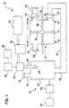
- the gas mixing apparatus 10 includes a fixed volume piston chamber 12 having a first gas delivery portion 14 with an inlet 16 for receiving mixed gas and an outlet 18 for delivering mixed gas to the patient airway 20 during an inspiratory portion of a breath cycle.
- the inlet includes a check valve 22 allowing one way flow of the mixed gas into the piston chamber; and the outlet similarly has a check valve 24 allowing one way flow of the mixed gas to the patient airway.
- the second portion 34 of the piston chamber preferably includes a vent 36, with a filter 38, open to the atmosphere.
- the gas mixing apparatus also includes gas mixing chamber means 39, which in the first preferred embodiment comprises at least one reservoir or reservoir chamber 40 for mixing a selected gas with air, with at least one reservoir having an air inlet 42, typically provided with a filter 44, and otherwise open to the ambient atmosphere for admitting air to the reservoir.
- the reservoir 40 is connected in fluid communication with the inlet 16 of the piston chamber, as will be further explained below.
- the reservoir can also comprise a plurality of reservoirs or reservoir chambers 40 connected in series in fluid communication with the inlet 16 of the piston chamber, although such multiple reservoirs can also be connected in parallel.
- the reservoir also preferably includes a flow limiting inlet 46 for admitting the selected gas to the reservoir.
- the flow limiting inlet preferably comprises a sonic flow limiting orifice 48 allowing a maximum mass flow rate of the selected gas to the reservoir, provided that the ratio of upstream to downstream pressure is typically greater than about 2.
- the sonic flow limiting orifice is of the commonly known type of orifice that limits the speed of flow of fluid through the orifice to less than the speed of sound in the fluid, allowing for a constant mass flow rate upstream of the orifice despite downstream pressure variations. Oxygen flow rate is advantageously limited to an absolute maximum by the sonic flow limiting orifice.
- a source 50 of the selected gas is also provided, such as a tank of pressurized oxygen, for example, for supplying a flow of the selected gas to the reservoir.
- Gas pressure regulating means 52 is preferably connected in fluid communication to the high pressure source 50 of the selected gas for regulating the pressure of the gas supplied from the selected gas source, as will be further explained below.
- Valve means 54 for controlling the flow of the selected gas to the reservoir such as a solenoid valve, is provided in fluid communication between the pressure regulating means 52 and the flow limiting inlet 46 to the reservoir. The valve means is switchable between an open position in which the selected gas flows to the reservoir, and a closed position in which the selected gas is prevented from flowing to the reservoir.
- a control unit 58 typically connected to sensors (not shown) for monitoring the patient breathing cycle, is also preferably provided for controlling the valve means 54 to admit the selected gas into the reservoir during at least one interval of time during at least a portion of the breath cycle for a total period of time to obtain a selected proportion of the selected gas in the mixed gas, typically preset or selected through the control unit.
- the reservoir also includes an outlet 60 in fluid communication through conduit 61 with the inlet 16 to the piston chamber, so that after extension of the piston in the piston chamber to deliver gas to the patient airway, the piston moves to a retracted position during patient exhalation, returning to a base position, drawing mixed gas from the reservoir into the piston chamber.
- the solenoid valve is typically opened for a sufficient time to supply the desired proportion of oxygen in the mixed gas supplied to the piston chamber.
- the time during which the solenoid valve is switched open can be 100% of the time period in which the piston is retracting, and the reservoir means is being filled with gas, to produce 100% oxygen. If the solenoid valve is switched open 25% of the retraction period, a mixture is produced having about a 41% oxygen concentration.
- the concentration of the selected gas can be corrected for atmospheric changes by sensing atmospheric pressure changes with a pressure sensor, and a microprocessor, for example, that is responsive to signals from the pressure sensor to adjust the time that the solenoid valve is switched open.
- the movement of the reciprocating piston in the piston chamber is controlled by the control unit to deliver a quantity of mixed gas in the desired volume at the desired pressure to a patient.
- a flow limiting inlet for the selected gas By utilizing a flow limiting inlet for the selected gas, if the solenoid valve controlling the supply flow of the selected gas to the reservoir fails, and is stuck open, the selected gas will flow at the maximum rate allowed by the flow limiting inlet to the reservoir. Excess flow is vented to the atmosphere back through air vent 42 of the reservoir means, so that the failure will not result in excess pressure applied to the patient. If the solenoid valve is stuck closed, the supply of selected gas will not flow, but the patient will be ventilated with room air. In either case, a sensor 62 of the concentration of the selected gas in the mixed breathing gas can be provided, such as in the reservoir, or in the patient airway, for example, to operate an alarm 64 to alert an operator so that the problem can be corrected.
- an upstream gas supply gauge pressure of 101.4 kPa (14.7 psig) can provide a 2 to 1 ratio of absolute pressures, thus ensuring that sonic flow conditions are met. Allowing for pressure drops in the system, a pressure regulator is set to control output of the gas source to about 196.5 kPa (28.5 psig) to ensure that the upstream requirement of 101.4 kPa (14.7 psig)is met in all atmospheric conditions.
- Atmospheric pressure sensing means 66 can also be provided and connected to the control unit, to monitor the actual ambient atmospheric pressure, for adjusting the total period of time of admitting the selected gas to the reservoir means to compensate for variations in atmospheric pressure to obtain the selected proportion of the selected gas in the mixed gas.
- the pressure regulating means 52 can in one preferred embodiment employ a demand valve 68 for reducing the pressure of the selected gas supplied from source 50 to atmospheric pressure.
- the selected gas is typically oxygen, stored in the source tank at a pressure of approximately 200 bar, and is supplied through a pressure regulator 70 connected to the source tank at approximately 207 to 690 kPa (30-100 psi) output.
- a pressure sensor 72 such as a pressure sensitive switch triggered when the supply pressure falls below about 207 kPa (30 psig) is positioned upstream of the demand valve, between the demand valve and the pressure regulator 70, to signal low oxygen supply, such as an alarm 73.
- Another pressure sensor 74 such as a pressure switch triggered when the gas pressure rises above about 30 cm H 2 O, is positioned downstream of the demand valve, to detect an open failure of the demand valve.
- the demand valve monitoring pressure sensor 74 is connected via control means to a solenoid valve 76 positioned in the selected gas supply line to the reservoir to regulate flow to the cylinder.
- solenoid valve 76 When failure of the demand valve is detected by the sensor, the demand valve pressure sensor 74 generates a signal causing solenoid valve 76, typically upstream of the demand valve, to close when the demand valve fails, shutting off the oxygen supply, preventing oxygen under excessive pressure from reaching the mixing chamber and the patient airway.
- the air and the oxygen supplied at approximately atmospheric pressure can, in one currently preferred embodiment, be introduced into a blender 80 that controls the mixture by providing mechanically adjustable resistance in the air and oxygen paths.
- the blender 80 includes an interior chamber 82 having a first inlet 84 for introducing a first selected gas, such as oxygen, received from the demand valve 68 through line 86, and a second inlet 88, for admitting a second selected gas, such as air, such as from line 90.
- the blender also includes an outlet 92 for conducting the blended first and second gases through the outlet line 94 to the piston chamber, or to one or more reservoirs leading to the piston chamber.
- the blender also includes a movable plate 96 that can be moved to cover all or a portion of one or both inlets 84 and 88 to offer a mechanically adjustable resistance in the paths of the first and second gases to the outlet.
- the plate 96 can, for example be mounted in the blender to rotate about a pivot point 98, so as to cover or uncover the inlets as desired to control the proportions of the gases being mixed.
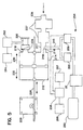
- the gas mixing apparatus 110 includes a fixed volume piston chamber 112 with a first gas delivery portion 114, an inlet 116 for receiving mixed gas, and an outlet 118 for delivering mixed gas to the patient airway 120.
- the inlet includes a check valve 122 allowing mixed gas to flow in only one direction, into the piston chamber.
- the outlet also includes a check valve 124 allowing mixed gas to flow only to the patient airway.
- a reciprocating piston 126 mounted to a piston rod 128 that is connected a rack and pinion motor 129 for moving the piston, is disposed within the piston chamber, and is movable within the piston chamber between an extended position 130 in the first gas delivery portion 114 of the piston chamber and a retracted position 132 in a second portion 134 of the piston chamber on the opposite side of the piston from first gas delivery portion 114 of the piston chamber.
- the second portion 134 of the piston chamber preferably includes an air inlet 136, with a filter 138, open to the atmosphere.
- the gas mixing chamber 139 is provided in the second portion 134 of the piston chamber, eliminating the requirement for a separate reservoir, and thereby making the gas mixing apparatus considerably more compact. As is shown in Fig. 4 and will be further explained below, the gas mixing chamber 139 is connected in fluid communication with the inlet 116 of the piston chamber.
- the gas mixing chamber 139 also preferably includes a flow limiting inlet 146 for admitting the selected gas to the gas mixing chamber.
- the flow limiting inlet preferably comprises a sonic flow limiting orifice 148 allowing a maximum mass flow rate of the selected gas to the gas mixing chamber, provided that the ratio of upstream to downstream pressure is typically greater than about 2.
- the sonic flow limiting orifice is of the commonly known type of orifice that limits the speed of flow of fluid through the orifice to less than the speed of sound in the fluid, allowing for a constant mass flow rate upstream of the orifice despite downstream pressure variations. Oxygen flow rate is advantageously limited to an absolute maximum by the sonic flow limiting orifice.
- a source 150 of the selected gas is also provided, such as a tank of pressurized oxygen, for example, for supplying a flow of the selected gas to the gas mixing chamber.
- Gas pressure regulating means 52 is preferably connected in fluid communication to the high pressure source 150 of the selected gas for regulating the pressure of the gas supplied from the selected gas source.
- the pressure regulating means 52 shown in Fig. 4 is substantially identical to the pressure regulating means 52 of Fig. 1 and can equally comprise the demand valve arrangement 52 and blender 80 as described above with reference to Fig. 3.
- Valve means 154 for regulating the flow of the selected gas to the gas mixing chamber such as a solenoid valve, is provided in fluid communication between the pressure regulating means 52 and the flow limiting inlet 146 to the gas mixing chamber.
- the valve means is switchable between an open position in which the selected gas flows to the gas mixing chamber, and a closed position in which the selected gas is prevented from flowing to the gas mixing chamber.
- a control unit 158 typically connected to sensors (not shown) for monitoring the patient breathing cycle, is also preferably provided for controlling the valve means 154 to admit the selected gas to the gas mixing chamber during at least one interval of time during at least a portion of the breath cycle for a total period of time to obtain a selected proportion of the selected gas in the mixed gas, typically preset or selected through the control unit.
- the gas mixing chamber also includes an outlet 160 in fluid communication through conduit 161 with the inlet 116 to the piston chamber, so that after extension of the piston in the piston chamber to deliver gas to the patient airway, the piston moves to a retracted position during patient exhalation, returning to a base position, drawing mixed gas from the gas mixing chamber into the gas delivery side of the piston chamber.
- the solenoid valve is typically opened for a sufficient time to supply the desired proportion of oxygen in the mixed gas supplied to the piston chamber.
- the concentration of the selected gas can be corrected for atmospheric changes by sensing atmospheric pressure changes with a pressure sensor, and a microprocessor, for example, that is responsive to signals from the pressure sensor to adjust the time that the solenoid valve is switched open.
- the movement of the reciprocating piston in the piston chamber is controlled by the control unit to deliver a quantity of mixed gas in the desired volume at the desired pressure to a patient.
- a flow limiting inlet for the selected gas such as the sonic flow limiting orifice in the gas mixing apparatus
- the solenoid valve controlling the supply flow of the selected gas to the gas mixing chamber fails, and is stuck open, the selected gas will flow at the maximum rate allowed by the flow limiting inlet to the gas mixing chamber. Excess flow is vented to the atmosphere back through air vent 136 to the gas mixing chamber so that the failure will not result in excess pressure applied to the patient. If the solenoid valve is stuck closed, the supply of selected gas will not flow, but the patient will be ventilated with room air.
- a sensor 162 of the concentration of the selected gas in the mixed breathing gas can be provided, such as in the gas mixing chamber, in the line 161 between the gas mixing chamber and the gas delivery portion of the piston chamber, or in the patient airway, for example, to operate an alarm 164 to alert an operator so that the problem can be corrected.
- Atmospheric pressure sensing means 166 can also be provided and connected to the control unit, to monitor the actual ambient atmospheric pressure, for adjusting the total period of time of admitting the selected gas to the gas mixing chamber to compensate for variations in atmospheric pressure to obtain the selected proportion of the selected gas in the mixed gas.
- the gas mixing apparatus 210 includes a fixed volume piston chamber 212 with a gas delivery portion 214, an inlet 216 for receiving mixed gas, and an outlet 218 for delivering mixed gas to the patient airway 220.
- the outlet preferably includes a check valve 224 allowing mixed gas to flow only to the patient airway.
- a reciprocating piston 226 is mounted within the piston cylinder to piston rod 228 that can in turn be driven, for example, by a rack and pinion motor 229.
- the piston is movable between an extended position 230 in the gas delivery portion 214 of the piston chamber and a retracted position 232.
- An air inlet 236 open to the atmosphere can also advantageously be connected to the piston chamber inlet 216 through one or more enlarged air capacitor chambers 237.
- the piston chamber inlet 216 also preferably includes a flow limiting inlet 246 having a sonic flow limiting orifice 248 for admitting the selected gas to the gas mixing chamber.
- the inlet 246 can admit the selected gas directly to the piston chamber as the piston retracts. Gas mixing occurs in the manifold 217 of the piston chamber inlet 216 and in the piston chamber itself as the selected gas and air are admitted to the piston chamber, eliminating the requirement for a separate reservoir, and thereby making the gas mixing apparatus considerably more compact.
- a source 250 of the selected gas is also provided, such as a tank of pressurized oxygen, for example, connected in fluid communication to the gas pressure regulating means 52 for regulating the pressure of the gas supplied from the selected gas source.
- the pressure regulating means 52 shown in Fig. 5 is substantially identical to the pressure regulating means 52 of Fig. 1 and can equally comprise the demand valve arrangement 52 and blender 80 as described above with reference to Fig. 3.
- Valve means 254 such as a solenoid valve or plurality of solenoid valves, is also provided between the pressure regulating means 52 and the flow limiting inlet 246 for regulating the flow of the selected gas to the piston chamber.
- the valve means is switchable between an open position in which the selected gas flows to the gas mixing chamber, and a closed position in which the selected gas is prevented from flowing to the gas mixing chamber.
- Introduction of the selected gas and air into a gas delivery chamber can thus be sequenced in the mixing cycle, during retraction of the piston to draw breathing gas into the piston chamber, with a pulse of the selected gas followed by a pulse of air, to insure that the selected gas will enter the piston chamber first, to facilitate adequate mixing of the selected gas and air in the manifold and in the piston chamber for delivery to a patient.
- the solenoid valve is typically opened for a sufficient time to supply the desired proportion of'oxygen in the mixed gas supplied to the piston chamber.
- the flow limiting inlet to the gas mixing chamber preferably permits the supply of a mass flow rate equal to the mass flow rate produced by the retracting piston.
- the movement of the reciprocating piston in the piston chamber is controlled by the control unit 258 to deliver a quantity of mixed gas in the desired volume at the desired pressure to a patient.
- the concentration of the selected gas can be corrected for atmospheric changes by sensing atmospheric pressure changes with a pressure sensor 266, and for temperature changes measured by a temperature sensor 267, and a microprocessor, for example, that is responsive to signals from the pressure sensor and temperature sensor to adjust the time that the solenoid valve is switched open.
- a sensor 262 of the concentration of the selected gas can also be connected with the outlet 218 or the patient airway 220, for example, to operate an alarm 264 to alert an operator so that such a problem can be detected and corrected.
- a supply flow of the selected gas such as oxygen
- the gas mixing chamber means either a reservoir in the first embodiment of the apparatus, or the gas mixing chamber in piston chamber, in the second preferred embodiment of the apparatus.
- the piston is extended in the piston chamber to deliver a flow of mixed gas from the gas delivery portion of the piston chamber to the patient airway, and is then retracted in a continuing cycle to draw gas into the gas delivery portion of the piston chamber.
- the invention provides for providing the supply flow of the selected gas to the reservoir means to admit the selected gas to the reservoir means during at least one interval of time period during the breath cycle to minimize peak flow rate of the supply flow, and for a total period of time to obtain a selected proportion of the selected gas in the mixed gas.
- the selected gas can, for example, be' admitted intermittently or continuously during one, or multiple opening periods during the period of retraction of the piston. Some of the selected gas can also be admitted to the gas mixing chamber means before the piston starts retraction as well, to reduce peak flow rate of the selected gas supply, since this will allow the total amount of time during a breath cycle that the selected gas is admitted to the gas mixing chamber to be longer.
- the selected gas is typically admitted to the gas mixing chamber means during retraction of the piston, when the mixed gas is drawn into the delivery side of the piston chamber, the selected gas can also be admitted to the gas mixing chamber means during extension of the piston to deliver mixed gas to the patient airway, to allow a reduction of the minimum peak flow of the supply flow of the selected gas.
- the mixed gas is then conducted to a displacement side of the piston chamber, and delivered to a patient airway by extension of the piston in the piston chamber.
- the selected gas and air can be mixed sequentially in alternating pulses, and can thus be sequenced in the mixing cycle, during retraction of the piston to draw breathing gas into the chamber in which the gases are to be mixed. It is particularly advantageous to provide a pulse of the selected gas followed by a pulse of air, to insure that the selected gas will not escape from the chamber in which the gases are to be mixed, and to facilitate adequate mixing of the selected gas and air.
- the selected gas and air can be introduced into the chamber in which they are to be mixed in a plurality of pairs of pulses comprising a pulse of the selected gas followed by a pulse of air.
- a plurality of pulses of the selected gas can be interspersed during drawing of air and selected gas into the chamber in which they are to be mixed.
- the demand valve and mechanically variable resistance blender configuration can be connected to deliver gas directly to the piston cylinder, to one or more reservoirs for the piston cylinder, or to a manifold leading to the piston cylinder, in place of the sonic flow limiting orifices described above.
- the present invention provides for a gas mixing apparatus that regulates the pressure of a selected gas to approximately ambient atmospheric pressure, for mixing with air at ambient atmospheric pressure for use as a breathing gas in a ventilator.
- the pressure of the selected gas is limited to a maximum pressure, so that even if a valve for admitting the selected gas for mixing at ambient pressure fails, breathing gas delivered to the patient will not reach an excessive pressure.
- the invention further allows a desired sequencing of introduction of the gases to be mixed into a chamber of the ventilator in which the gases are to be mixed, to facilitate adequate mixing.
Claims (14)
- Appareil mélangeur de gaz pour un système de ventilateur destiné à fournir un mélange de gaz respiratoire dans les voies aériennes d'un patient, comprenant :une chambre à pompe (12) ayant une première partie d'émission de gaz (14) et une seconde partie (34) opposée, la première partie d'émission de gaz de la chambre à pompe ayant une entrée (16) pour recevoir le mélange de gaz et une sortie (18) pour émettre le mélange de gaz dans les voies aériennes du patient pendant une partie d'inspiration d'un cycle respiratoire ;un élément de déplacement de gaz (26) disposé à l'intérieur de la chambre à pompe et mobile entre une position déployée dans la première partie d'émission de gaz de la chambre à pompe et une position rétractée dans la seconde partie de la chambre à pompe ; etdes moyens (28) pour faire bouger l'élément de déplacement de gaz entre les positions déployée et rétractée ; caractérisé par :des moyens de mélange de gaz (40) pour mélanger un premier gaz sélectionné avec un second gaz sélectionné, les moyens de mélange de gaz ayant une entrée (42) débouchant sur une source (50) du second gaz sélectionné pour admettre le second gaz sélectionné dans les moyens de mélange de gaz et une entrée de limitation de débit (46) pour admettre le premier gaz sélectionné dans les moyens de mélange de gaz ;des moyens formant vanne (54) pour réguler le débit du premier gaz sélectionné dans les moyens de mélange de gaz ; etdes moyens de commande (58) pour commander les moyens formant vanne pour faire entrer le premier gaz sélectionné dans les moyens de mélange de gaz pendant au moins un intervalle de temps au cours d'au moins une partie du cycle respiratoire afin d'obtenir une proportion prédéterminée du premier gaz sélectionné dans le gaz mélangé.
- Appareil mélangeur de gaz selon la revendication 1, dans lequel la seconde partie (34) de la chambre à pompe (14) comprend un évent (36) débouchant dans l'atmosphère.
- Appareil mélangeur de gaz selon la revendication 1, l'entrée (16) de la partie d'émission de gaz de la chambre à pompe comprend un clapet de retenue (22) permettant l'écoulement dudit mélange de gaz dans ladite chambre à pompe, ladite sortie de la partie d'émission de la chambre à pompe comprend un second clapet de retenue (24) permettant l'écoulement dudit mélange de gaz dans les voies aériennes du patient.
- Appareil mélangeur de gaz selon la revendication 1, dans lequel lesdits moyens de mélange de gaz comprennent au moins une chambre à réservoir (40) raccordée en communication fluidique avec ladite entrée (16) de la partie d'émission de gaz de ladite chambre à pompe.
- Appareil mélangeur de gaz selon la revendication 1, dans lequel lesdits moyens de mélange de gaz comprennent une partie de mélange de gaz de ladite chambre à pompe (112) dans ladite seconde partie (134) de ladite chambre à pompe.
- Appareil mélangeur de gaz selon la revendication 1, dans lequel lesdits moyens de mélange de gaz comprennent une pluralité de chambres à réservoir (40) raccordées en série en communication fluidique avec ladite entrée (16) de la partie d'émission de gaz de ladite chambre à pompe (12).
- Appareil mélangeur de gaz selon la revendication 1, dans lequel lesdits moyens de mélange de gaz comprennent une pluralité de chambres à réservoir (40) raccordées en parallèle en communication fluidique avec ladite entrée (16) de la partie d'émission de gaz de ladite chambre à pompe (12).
- Appareil mélangeur de gaz selon la revendication 1, dans lequel lesdits moyens formant vanne (54) comprennent une électrovanne commutable d'une position ouverte dans laquelle ledit premier gaz sélectionné circule dans lesdits moyens de mélange de gaz (40), à une position fermée dans laquelle on empêche ledit premier gaz sélectionné de circuler dans lesdits moyens de mélange de gaz.
- Appareil mélangeur de gaz selon la revendication 1, dans lequel lesdits moyens formant vanne (54) comprennent une pluralité d'électrovannes, dont chacune peut être commutée d'une position ouverte dans laquelle ledit premier gaz sélectionné circule dans lesdits moyens de mélange de gaz (40), à une position fermée dans laquelle on empêche ledit premier gaz sélectionné de circuler dans lesdits moyens de mélange de gaz, chacune desdites électrovannes étant raccordée pour recevoir un flux dudit premier gaz sélectionné et étant raccordée séparément en communication fluidique avec lesdits moyens de mélange de gaz pour permettre l'écoulement dudit premier gaz sélectionné.
- Appareil mélangeur de gaz selon la revendication 1, comprenant en outre des moyens (62) pour surveiller la proportion du premier gaz sélectionné dans le mélange de gaz, lesdits moyens pour surveiller la proportion du premier gaz sélectionné dans le mélange de gaz comprend en outre des moyens d'alarme (64) pour alerter un opérateur lorsque la proportion du premier gaz sélectionné dans le mélange de gaz ne se trouve pas dans une plage de proportions sélectionnée du premier gaz sélectionné dans le mélange de gaz.
- Appareil mélangeur de gaz selon la revendication 1, comprenant en outre des moyens pour régler ladite période de temps globale d'admission dudit premier gaz sélectionné dans lesdits moyens de mélange de gaz afin de compenser des variations de la pression atmosphérique pour obtenir ladite proportion prédéterminée dudit premier gaz sélectionné dans le mélange de gaz.
- Appareil mélangeur de gaz selon la revendication 1, dans lequel lesdits moyens formant vanne comprennent une vanne à résistance variable comprenant un premier orifice d'entrée pour recevoir ledit premier gaz sélectionné, et une plaque mobile qui peut être déplacée pour recouvrir au moins une partie dudit premier orifice d'entrée afin d'offrir une résistance pouvant être réglée mécaniquement au flux dudit premier gaz sélectionné, ladite vanne à résistance variable comprend un second orifice d'admission pour recevoir ledit second gaz sélectionné, et ladite plaque mobile peut être déplacée pour recouvrir au moins une partie dudit second orifice d'entrée afin d'offrir une résistance pouvant être réglée mécaniquement au flux dudit second gaz sélectionné, lesdits moyens formant vanne à résistance variable comprennent en outre une chambre de mélange pour mélanger lesdits premier et second gaz sélectionnés, et un orifice de sortie pour lesdits premier et second gaz sélectionnés.
- Appareil mélangeur de gaz selon la revendication 12, dans lequel ladite source dudit premier gaz sélectionné délivre ledit premier gaz sélectionné à une pression supérieure à la pression atmosphérique, et comprenant en outre une vanne de régulation de la demande pour réduire la pression du premier gaz sélectionné délivré sous pression atmosphérique, ladite vanne de régulation de la demande étant raccordée en communication fluidique entre ladite source dudit premier gaz sélectionné et ladite vanne à résistance variable.
- Appareil mélangeur de gaz selon la revendication 13, comprenant en outre un capteur de pression placé en aval de la vanne de régulation de la demande afin de détecter un dysfonctionnement de la vanne de régulation de la demande et opérationnel pour générer un signal de dysfonctionnement lorsque le dysfonctionnement de la vanne de régulation de la demande est détecté, et comprenant en outre une électrovanne située en amont de la vanne de régulation de la demande raccordée audit capteur de pression situé en aval répondant audit signal de dysfonctionnement pour interrompre l'écoulement dudit gaz sélectionné, empêchant la pression excessive dudit gaz sélectionné d'atteindre les moyens de mélange de gaz.
Applications Claiming Priority (3)
| Application Number | Priority Date | Filing Date | Title |
|---|---|---|---|
| US38595195A | 1995-02-08 | 1995-02-08 | |
| US385951 | 1995-02-08 | ||
| PCT/IB1996/000214 WO1996024402A1 (fr) | 1995-02-08 | 1996-02-06 | Appareil melangeur de gaz pour un ventilateur |
Publications (2)
| Publication Number | Publication Date |
|---|---|
| EP0792177A1 EP0792177A1 (fr) | 1997-09-03 |
| EP0792177B1 true EP0792177B1 (fr) | 2002-05-22 |
Family
ID=23523568
Family Applications (1)
| Application Number | Title | Priority Date | Filing Date |
|---|---|---|---|
| EP96904224A Expired - Lifetime EP0792177B1 (fr) | 1995-02-08 | 1996-02-06 | Appareil melangeur de gaz pour un ventilateur |
Country Status (6)
| Country | Link |
|---|---|
| US (4) | US5664560A (fr) |
| EP (1) | EP0792177B1 (fr) |
| JP (1) | JPH10500347A (fr) |
| CA (1) | CA2187288A1 (fr) |
| DE (1) | DE69621320T2 (fr) |
| WO (1) | WO1996024402A1 (fr) |
Families Citing this family (153)
| Publication number | Priority date | Publication date | Assignee | Title |
|---|---|---|---|---|
| EP0792177B1 (fr) * | 1995-02-08 | 2002-05-22 | Puritan-Bennett Corporation | Appareil melangeur de gaz pour un ventilateur |
| SE9602415D0 (sv) | 1996-06-19 | 1996-06-19 | Siemens Elema Ab | Apparatus for supplying air and at least one additional gas to a living being |
| US5701883A (en) * | 1996-09-03 | 1997-12-30 | Respironics, Inc. | Oxygen mixing in a blower-based ventilator |
| CA2278053C (fr) | 1997-01-17 | 2010-03-23 | Messer Griesheim Austria Ges.Mbh | Controleur de debit de gaz medicaux |
| US5881723A (en) | 1997-03-14 | 1999-03-16 | Nellcor Puritan Bennett Incorporated | Ventilator breath display and graphic user interface |
| US5918597A (en) * | 1998-01-15 | 1999-07-06 | Nellcor Puritan Bennett | Peep control in a piston ventilator |
| US6076523A (en) * | 1998-01-15 | 2000-06-20 | Nellcor Puritan Bennett | Oxygen blending in a piston ventilator |
| US6321748B1 (en) | 1998-03-10 | 2001-11-27 | Nellcor Puritan Bennett | Closed loop control in a piston ventilator |
| SE9802827D0 (sv) * | 1998-08-25 | 1998-08-25 | Siemens Elema Ab | Ventilator |
| WO2000059566A1 (fr) * | 1999-04-07 | 2000-10-12 | Event Medical Limited | Appareil respiratoire |
| US6579951B1 (en) * | 1999-06-08 | 2003-06-17 | Life Medical Sciences, Inc. | Chain-extended or crosslinked polyethylene oxide/polypropylene oxide/polyethylene oxide block polymer with optional polyester blocks |
| CN1073878C (zh) * | 1999-10-15 | 2001-10-31 | 中国科学院合肥智能机械研究所 | 自动控制气体混合泵 |
| JP2004511311A (ja) * | 2000-10-19 | 2004-04-15 | マリンクロッド・インコーポレイテッド | 二重気体供給部を備える人工呼吸器 |
| US7387123B2 (en) * | 2001-11-30 | 2008-06-17 | Viasys Manufacturing, Inc. | Gas identification system and volumetrically correct gas delivery system |
| DE10205845C1 (de) * | 2002-02-13 | 2002-10-31 | Draeger Medical Ag | Gasmischer mit mehreren Ejektoren für ein medizinisches Beatmungsgerät |
| SE0201212D0 (sv) * | 2002-04-23 | 2002-04-23 | Siemens Elema Ab | Anaesthetic Delivery System |
| US7654975B2 (en) * | 2003-04-24 | 2010-02-02 | Northgate Technologies, Inc. | Mixed-gas insufflation system |
| FR2858236B1 (fr) | 2003-07-29 | 2006-04-28 | Airox | Dispositif et procede de fourniture de gaz respiratoire en pression ou en volume |
| US8118024B2 (en) | 2003-08-04 | 2012-02-21 | Carefusion 203, Inc. | Mechanical ventilation system utilizing bias valve |
| US7607437B2 (en) | 2003-08-04 | 2009-10-27 | Cardinal Health 203, Inc. | Compressor control system and method for a portable ventilator |
| WO2005013879A2 (fr) * | 2003-08-04 | 2005-02-17 | Pulmonetic Systems, Inc. | Systeme de ventilateur portable |
| US8156937B2 (en) | 2003-08-04 | 2012-04-17 | Carefusion 203, Inc. | Portable ventilator system |
| DE602004024808D1 (de) * | 2003-10-07 | 2010-02-04 | Northgate Technologies Inc | System für die abgabe einer substanz in eine körperhöhle |
| DE602004031034D1 (de) | 2003-10-31 | 2011-02-24 | Trudell Medical Int | System zur manipulierung eines katheters für die ablage einer substanz in einer körperhöhle |
| US20060292018A1 (en) * | 2004-07-08 | 2006-12-28 | Jones Philip E | Hydraulic powered pneumatic super charger for on-board inert gas generating system |
| FR2875138B1 (fr) | 2004-09-15 | 2008-07-11 | Mallinckrodt Dev France Sa | Procede de regulation pour un humidificateur chauffant |
| US7615028B2 (en) * | 2004-12-03 | 2009-11-10 | Chf Solutions Inc. | Extracorporeal blood treatment and system having reversible blood pumps |
| WO2007062400A2 (fr) * | 2005-11-23 | 2007-05-31 | Jianguo Sun | Procede et appareil destines a fournir une pression positive dans les voies aeriennes d'un patient |
| US8006692B2 (en) | 2005-12-02 | 2011-08-30 | Carefusion 2200, Inc. | Gas blender with auxiliary mixed gas outlet |
| US8021310B2 (en) | 2006-04-21 | 2011-09-20 | Nellcor Puritan Bennett Llc | Work of breathing display for a ventilation system |
| US8663271B2 (en) | 2006-08-04 | 2014-03-04 | Northgate Technologies, Inc. | In-dwelling port for access into a body |
| US7784461B2 (en) | 2006-09-26 | 2010-08-31 | Nellcor Puritan Bennett Llc | Three-dimensional waveform display for a breathing assistance system |
| US8902568B2 (en) | 2006-09-27 | 2014-12-02 | Covidien Lp | Power supply interface system for a breathing assistance system |
| US20080078390A1 (en) * | 2006-09-29 | 2008-04-03 | Nellcor Puritan Bennett Incorporated | Providing predetermined groups of trending parameters for display in a breathing assistance system |
| US20080183057A1 (en) * | 2006-11-13 | 2008-07-31 | John Taube | Display, data storage and alarm features of an adaptive oxygen controller |
| DE102006055779B3 (de) * | 2006-11-25 | 2008-03-13 | Dräger Medical AG & Co. KG | Gasmischvorrichtung für Beatmungsgeräte |
| CN101310786B (zh) * | 2007-12-28 | 2012-04-18 | 北京谊安医疗系统股份有限公司 | 氧浓度调节装置及方法 |
| EP2257328A2 (fr) | 2008-03-27 | 2010-12-08 | Nellcor Puritan Bennett LLC | Systèmes d'assistance respiratoire avec man uvres de recrutement pulmonaire |
| US8425428B2 (en) | 2008-03-31 | 2013-04-23 | Covidien Lp | Nitric oxide measurements in patients using flowfeedback |
| US8272380B2 (en) | 2008-03-31 | 2012-09-25 | Nellcor Puritan Bennett, Llc | Leak-compensated pressure triggering in medical ventilators |
| WO2009123980A1 (fr) | 2008-03-31 | 2009-10-08 | Nellcor Puritan Bennett Llc | Système et procédé pour déterminer une fuite de système de ventilation pendant des périodes stables lors d'une respiration |
| US20110023879A1 (en) * | 2008-03-31 | 2011-02-03 | Nellcor Puritan Bennett Llc | Ventilator Based On A Fluid Equivalent Of The "Digital To Analog Voltage" Concept |
| US8267085B2 (en) | 2009-03-20 | 2012-09-18 | Nellcor Puritan Bennett Llc | Leak-compensated proportional assist ventilation |
| US8792949B2 (en) | 2008-03-31 | 2014-07-29 | Covidien Lp | Reducing nuisance alarms |
| US8746248B2 (en) | 2008-03-31 | 2014-06-10 | Covidien Lp | Determination of patient circuit disconnect in leak-compensated ventilatory support |
| US20090241960A1 (en) * | 2008-04-01 | 2009-10-01 | Event Medical, Inc. | Dual high and low pressure breathing system |
| WO2009149355A1 (fr) | 2008-06-06 | 2009-12-10 | Nellcor Puritan Bennett Llc | Systèmes et procédés de surveillance et d'affichage d'informations respiratoires |
| US20100051026A1 (en) | 2008-09-04 | 2010-03-04 | Nellcor Puritan Bennett Llc | Ventilator With Controlled Purge Function |
| US8551006B2 (en) | 2008-09-17 | 2013-10-08 | Covidien Lp | Method for determining hemodynamic effects |
| US8424520B2 (en) | 2008-09-23 | 2013-04-23 | Covidien Lp | Safe standby mode for ventilator |
| EP2349420B1 (fr) | 2008-09-25 | 2016-08-31 | Covidien LP | Compensation par action directe à base d'inversion d'une dynamique de déclencheur inspiratoire dans des ventilateurs médicaux |
| US8181648B2 (en) | 2008-09-26 | 2012-05-22 | Nellcor Puritan Bennett Llc | Systems and methods for managing pressure in a breathing assistance system |
| US8302600B2 (en) | 2008-09-30 | 2012-11-06 | Nellcor Puritan Bennett Llc | Battery management for a breathing assistance system |
| US8439032B2 (en) | 2008-09-30 | 2013-05-14 | Covidien Lp | Wireless communications for a breathing assistance system |
| US8652064B2 (en) | 2008-09-30 | 2014-02-18 | Covidien Lp | Sampling circuit for measuring analytes |
| US8585412B2 (en) | 2008-09-30 | 2013-11-19 | Covidien Lp | Configurable respiratory muscle pressure generator |
| US8393323B2 (en) | 2008-09-30 | 2013-03-12 | Covidien Lp | Supplemental gas safety system for a breathing assistance system |
| US8302602B2 (en) | 2008-09-30 | 2012-11-06 | Nellcor Puritan Bennett Llc | Breathing assistance system with multiple pressure sensors |
| US8434479B2 (en) | 2009-02-27 | 2013-05-07 | Covidien Lp | Flow rate compensation for transient thermal response of hot-wire anemometers |
| US8424521B2 (en) | 2009-02-27 | 2013-04-23 | Covidien Lp | Leak-compensated respiratory mechanics estimation in medical ventilators |
| US8418691B2 (en) | 2009-03-20 | 2013-04-16 | Covidien Lp | Leak-compensated pressure regulated volume control ventilation |
| CN101507854B (zh) * | 2009-03-23 | 2011-04-20 | 王中 | 带压缩空气的呼吸机空氧混合装置 |
| US9186075B2 (en) * | 2009-03-24 | 2015-11-17 | Covidien Lp | Indicating the accuracy of a physiological parameter |
| US8776790B2 (en) | 2009-07-16 | 2014-07-15 | Covidien Lp | Wireless, gas flow-powered sensor system for a breathing assistance system |
| US8789529B2 (en) | 2009-08-20 | 2014-07-29 | Covidien Lp | Method for ventilation |
| US8469031B2 (en) | 2009-12-01 | 2013-06-25 | Covidien Lp | Exhalation valve assembly with integrated filter |
| US8439037B2 (en) | 2009-12-01 | 2013-05-14 | Covidien Lp | Exhalation valve assembly with integrated filter and flow sensor |
| US8469030B2 (en) | 2009-12-01 | 2013-06-25 | Covidien Lp | Exhalation valve assembly with selectable contagious/non-contagious latch |
| US8439036B2 (en) | 2009-12-01 | 2013-05-14 | Covidien Lp | Exhalation valve assembly with integral flow sensor |
| US8547062B2 (en) | 2009-12-02 | 2013-10-01 | Covidien Lp | Apparatus and system for a battery pack assembly used during mechanical ventilation |
| US8434481B2 (en) | 2009-12-03 | 2013-05-07 | Covidien Lp | Ventilator respiratory gas accumulator with dip tube |
| US8482415B2 (en) | 2009-12-04 | 2013-07-09 | Covidien Lp | Interactive multilevel alarm |
| US20110132369A1 (en) | 2009-12-04 | 2011-06-09 | Nellcor Puritan Bennett Llc | Ventilation System With System Status Display |
| US9119925B2 (en) | 2009-12-04 | 2015-09-01 | Covidien Lp | Quick initiation of respiratory support via a ventilator user interface |
| US8924878B2 (en) | 2009-12-04 | 2014-12-30 | Covidien Lp | Display and access to settings on a ventilator graphical user interface |
| US9262588B2 (en) | 2009-12-18 | 2016-02-16 | Covidien Lp | Display of respiratory data graphs on a ventilator graphical user interface |
| US8499252B2 (en) | 2009-12-18 | 2013-07-30 | Covidien Lp | Display of respiratory data graphs on a ventilator graphical user interface |
| US8400290B2 (en) | 2010-01-19 | 2013-03-19 | Covidien Lp | Nuisance alarm reduction method for therapeutic parameters |
| US8707952B2 (en) | 2010-02-10 | 2014-04-29 | Covidien Lp | Leak determination in a breathing assistance system |
| US9302061B2 (en) | 2010-02-26 | 2016-04-05 | Covidien Lp | Event-based delay detection and control of networked systems in medical ventilation |
| US8511306B2 (en) | 2010-04-27 | 2013-08-20 | Covidien Lp | Ventilation system with system status display for maintenance and service information |
| US8539949B2 (en) | 2010-04-27 | 2013-09-24 | Covidien Lp | Ventilation system with a two-point perspective view |
| US8453643B2 (en) | 2010-04-27 | 2013-06-04 | Covidien Lp | Ventilation system with system status display for configuration and program information |
| US8638200B2 (en) | 2010-05-07 | 2014-01-28 | Covidien Lp | Ventilator-initiated prompt regarding Auto-PEEP detection during volume ventilation of non-triggering patient |
| US8607791B2 (en) | 2010-06-30 | 2013-12-17 | Covidien Lp | Ventilator-initiated prompt regarding auto-PEEP detection during pressure ventilation |
| US8607789B2 (en) | 2010-06-30 | 2013-12-17 | Covidien Lp | Ventilator-initiated prompt regarding auto-PEEP detection during volume ventilation of non-triggering patient exhibiting obstructive component |
| US8607790B2 (en) | 2010-06-30 | 2013-12-17 | Covidien Lp | Ventilator-initiated prompt regarding auto-PEEP detection during pressure ventilation of patient exhibiting obstructive component |
| US8607788B2 (en) | 2010-06-30 | 2013-12-17 | Covidien Lp | Ventilator-initiated prompt regarding auto-PEEP detection during volume ventilation of triggering patient exhibiting obstructive component |
| US8676285B2 (en) | 2010-07-28 | 2014-03-18 | Covidien Lp | Methods for validating patient identity |
| US8554298B2 (en) | 2010-09-21 | 2013-10-08 | Cividien LP | Medical ventilator with integrated oximeter data |
| US8757153B2 (en) | 2010-11-29 | 2014-06-24 | Covidien Lp | Ventilator-initiated prompt regarding detection of double triggering during ventilation |
| US8757152B2 (en) | 2010-11-29 | 2014-06-24 | Covidien Lp | Ventilator-initiated prompt regarding detection of double triggering during a volume-control breath type |
| US8595639B2 (en) | 2010-11-29 | 2013-11-26 | Covidien Lp | Ventilator-initiated prompt regarding detection of fluctuations in resistance |
| US8676529B2 (en) | 2011-01-31 | 2014-03-18 | Covidien Lp | Systems and methods for simulation and software testing |
| US8788236B2 (en) | 2011-01-31 | 2014-07-22 | Covidien Lp | Systems and methods for medical device testing |
| US8783250B2 (en) | 2011-02-27 | 2014-07-22 | Covidien Lp | Methods and systems for transitory ventilation support |
| US9038633B2 (en) | 2011-03-02 | 2015-05-26 | Covidien Lp | Ventilator-initiated prompt regarding high delivered tidal volume |
| US8714154B2 (en) | 2011-03-30 | 2014-05-06 | Covidien Lp | Systems and methods for automatic adjustment of ventilator settings |
| US8776792B2 (en) | 2011-04-29 | 2014-07-15 | Covidien Lp | Methods and systems for volume-targeted minimum pressure-control ventilation |
| US9629971B2 (en) | 2011-04-29 | 2017-04-25 | Covidien Lp | Methods and systems for exhalation control and trajectory optimization |
| US9089657B2 (en) | 2011-10-31 | 2015-07-28 | Covidien Lp | Methods and systems for gating user initiated increases in oxygen concentration during ventilation |
| US9364624B2 (en) | 2011-12-07 | 2016-06-14 | Covidien Lp | Methods and systems for adaptive base flow |
| US9498589B2 (en) | 2011-12-31 | 2016-11-22 | Covidien Lp | Methods and systems for adaptive base flow and leak compensation |
| US9022031B2 (en) | 2012-01-31 | 2015-05-05 | Covidien Lp | Using estimated carinal pressure for feedback control of carinal pressure during ventilation |
| US9327089B2 (en) | 2012-03-30 | 2016-05-03 | Covidien Lp | Methods and systems for compensation of tubing related loss effects |
| US8844526B2 (en) | 2012-03-30 | 2014-09-30 | Covidien Lp | Methods and systems for triggering with unknown base flow |
| US9993604B2 (en) | 2012-04-27 | 2018-06-12 | Covidien Lp | Methods and systems for an optimized proportional assist ventilation |
| US9144658B2 (en) | 2012-04-30 | 2015-09-29 | Covidien Lp | Minimizing imposed expiratory resistance of mechanical ventilator by optimizing exhalation valve control |
| US10362967B2 (en) | 2012-07-09 | 2019-07-30 | Covidien Lp | Systems and methods for missed breath detection and indication |
| US9027552B2 (en) | 2012-07-31 | 2015-05-12 | Covidien Lp | Ventilator-initiated prompt or setting regarding detection of asynchrony during ventilation |
| WO2014057449A1 (fr) | 2012-10-14 | 2014-04-17 | Pecherer Evgeny | Outil et procédé d'introduction d'un tube endotrachéal |
| US9375542B2 (en) | 2012-11-08 | 2016-06-28 | Covidien Lp | Systems and methods for monitoring, managing, and/or preventing fatigue during ventilation |
| US9289573B2 (en) | 2012-12-28 | 2016-03-22 | Covidien Lp | Ventilator pressure oscillation filter |
| US9492629B2 (en) | 2013-02-14 | 2016-11-15 | Covidien Lp | Methods and systems for ventilation with unknown exhalation flow and exhalation pressure |
| USD731049S1 (en) | 2013-03-05 | 2015-06-02 | Covidien Lp | EVQ housing of an exhalation module |
| USD736905S1 (en) | 2013-03-08 | 2015-08-18 | Covidien Lp | Exhalation module EVQ housing |
| USD701601S1 (en) | 2013-03-08 | 2014-03-25 | Covidien Lp | Condensate vial of an exhalation module |
| USD731065S1 (en) | 2013-03-08 | 2015-06-02 | Covidien Lp | EVQ pressure sensor filter of an exhalation module |
| USD693001S1 (en) | 2013-03-08 | 2013-11-05 | Covidien Lp | Neonate expiratory filter assembly of an exhalation module |
| USD731048S1 (en) | 2013-03-08 | 2015-06-02 | Covidien Lp | EVQ diaphragm of an exhalation module |
| USD692556S1 (en) | 2013-03-08 | 2013-10-29 | Covidien Lp | Expiratory filter body of an exhalation module |
| USD744095S1 (en) | 2013-03-08 | 2015-11-24 | Covidien Lp | Exhalation module EVQ internal flow sensor |
| US9358355B2 (en) | 2013-03-11 | 2016-06-07 | Covidien Lp | Methods and systems for managing a patient move |
| US9981096B2 (en) | 2013-03-13 | 2018-05-29 | Covidien Lp | Methods and systems for triggering with unknown inspiratory flow |
| US9950135B2 (en) | 2013-03-15 | 2018-04-24 | Covidien Lp | Maintaining an exhalation valve sensor assembly |
| EP3018477B1 (fr) * | 2013-07-03 | 2018-10-24 | PHC Holdings Corporation | Dispositif de mesure de gaz expiré, et son procédé de contrôle |
| US10064583B2 (en) | 2013-08-07 | 2018-09-04 | Covidien Lp | Detection of expiratory airflow limitation in ventilated patient |
| US20160228670A1 (en) * | 2013-09-11 | 2016-08-11 | Advanced Inhalation Therapies (Ait) Ltd. | System for nitric oxide inhalation |
| WO2015036938A1 (fr) | 2013-09-12 | 2015-03-19 | Pecherer Evgeny | Laryngoscope et poignée associée |
| US9675771B2 (en) | 2013-10-18 | 2017-06-13 | Covidien Lp | Methods and systems for leak estimation |
| US10133548B2 (en) | 2014-01-27 | 2018-11-20 | Roadwarez Inc. | System and method for providing mobile personal security platform |
| US9572595B1 (en) | 2014-03-05 | 2017-02-21 | Northgate Technologies Inc. | In-dwelling port for access into a body |
| US10786145B2 (en) | 2014-05-22 | 2020-09-29 | Evgeny Pecherer | Laryngoscope |
| CN110393839B (zh) * | 2014-05-27 | 2023-03-24 | 费雪派克医疗保健有限公司 | 用于医疗装置的气体混合和测量 |
| WO2015181773A1 (fr) * | 2014-05-28 | 2015-12-03 | Pecherer Evgeny | Dispositif de ventilation-réanimation et procédé de ventilation |
| US9808591B2 (en) | 2014-08-15 | 2017-11-07 | Covidien Lp | Methods and systems for breath delivery synchronization |
| US9950129B2 (en) | 2014-10-27 | 2018-04-24 | Covidien Lp | Ventilation triggering using change-point detection |
| US9925346B2 (en) | 2015-01-20 | 2018-03-27 | Covidien Lp | Systems and methods for ventilation with unknown exhalation flow |
| US10007238B1 (en) | 2015-01-22 | 2018-06-26 | John C. Taube | Oxygen mixing and delivery |
| US10271766B1 (en) * | 2015-03-20 | 2019-04-30 | Barron Associates, Inc. | Systems, devices, and/or methods for measuring metabolic energy expenditure |
| US20160287824A1 (en) * | 2015-04-03 | 2016-10-06 | Invent Medical Corporation | Ventilator |
| USD775345S1 (en) | 2015-04-10 | 2016-12-27 | Covidien Lp | Ventilator console |
| US11666720B2 (en) * | 2015-12-02 | 2023-06-06 | Fisher & Paykel Healthcare Limited | Flow path sensing for flow therapy apparatus |
| US10765822B2 (en) | 2016-04-18 | 2020-09-08 | Covidien Lp | Endotracheal tube extubation detection |
| EP3525857B1 (fr) | 2017-11-14 | 2020-01-29 | Covidien LP | Systèmes de ventilation spontanée par pression de commande |
| US11517691B2 (en) | 2018-09-07 | 2022-12-06 | Covidien Lp | Methods and systems for high pressure controlled ventilation |
| US11324954B2 (en) | 2019-06-28 | 2022-05-10 | Covidien Lp | Achieving smooth breathing by modified bilateral phrenic nerve pacing |
| US11779720B2 (en) | 2019-11-04 | 2023-10-10 | Vapotherm, Inc. | Methods, devices, and systems for improved oxygenation patient monitoring, mixing, and delivery |
| US11612706B2 (en) | 2019-11-25 | 2023-03-28 | John C. Taube | Methods, systems, and devices for controlling mechanical ventilation |
| CZ309212B6 (cs) * | 2020-04-02 | 2022-05-25 | České vysoké učení technické v Praze | Způsob provádění umělé plicní ventilace a zařízení k provádění tohoto způsobu |
| US20210316095A1 (en) * | 2020-04-09 | 2021-10-14 | Ator Labs, Inc. | Emergency ventilator system |
| WO2021207600A1 (fr) | 2020-04-10 | 2021-10-14 | Covidien Lp | Système de mélange de gaz pour un ventilateur médical |
| US11872349B2 (en) | 2020-04-10 | 2024-01-16 | Covidien Lp | Systems and methods for increasing ventilator oxygen concentration |
Family Cites Families (23)
| Publication number | Priority date | Publication date | Assignee | Title |
|---|---|---|---|---|
| DE213076C (fr) * | ||||
| US1488171A (en) * | 1918-08-01 | 1924-03-25 | Albert C Savidge | Vacuum pump |
| US1498471A (en) * | 1922-02-13 | 1924-06-17 | Vernon J Miller | Water elevator |
| US3527213A (en) * | 1966-07-21 | 1970-09-08 | Drager Otto H | Supply gas driven narcosis mixing apparatus |
| US3599633A (en) * | 1969-04-07 | 1971-08-17 | Puritan Bennett Corp | Volume-limited ventilator with compliance compensator |
| US3889669A (en) * | 1972-12-11 | 1975-06-17 | Puritan Bennett Corp | Respiration rate control system |
| US4023587A (en) * | 1975-11-14 | 1977-05-17 | Dragerwerk Aktiengesellschaft | Method and apparatus for mixing two gases in a predetermined proportion |
| US4121578A (en) * | 1976-10-04 | 1978-10-24 | The Bendix Corporation | Physiological responsive control for an oxygen regulator |
| FR2472937A1 (fr) * | 1980-01-04 | 1981-07-10 | Synthelabo | Dispositif de commande pour respirateur artificiel |
| US4340044A (en) * | 1980-03-20 | 1982-07-20 | Berkshire Research Partners | Volume ventilator |
| FR2483785A1 (fr) * | 1980-06-10 | 1981-12-11 | Air Liquide | Respirateur a correction automatique de ventilation |
| NL8007074A (nl) * | 1980-12-29 | 1982-07-16 | Honeywell Bv | Beademingstoestel. |
| US4587967A (en) * | 1985-07-09 | 1986-05-13 | Lifecare Services, Inc. | Oxygen enriched reciprocating piston respirator |
| US4832014A (en) * | 1985-10-02 | 1989-05-23 | Perkins Warren E | Method and means for dispensing two respirating gases by effecting a known displacement |
| US4702240A (en) * | 1986-07-22 | 1987-10-27 | Bear Medical Systems, Inc. | Demand-responsive gas blending system for medical ventilator |
| US4823593A (en) * | 1986-12-08 | 1989-04-25 | Normalair-Garrett (Holdings) Limited | Flueric partial pressure sensors |
| GB8704104D0 (en) * | 1987-02-21 | 1987-03-25 | Manitoba University Of | Respiratory system load apparatus |
| US4932401A (en) * | 1988-04-01 | 1990-06-12 | Perkins Warren E | Two-gas variable ratio, variable dose, metering system and method of use |
| JPH02102383A (ja) * | 1988-10-11 | 1990-04-13 | Asahi Chem Ind Co Ltd | 容積の調整可能な往復動ポンプ |
| US5299568A (en) * | 1989-06-22 | 1994-04-05 | Puritan-Bennett Corporation | Method for controlling mixing and delivery of respiratory gas |
| US5014694A (en) * | 1990-10-15 | 1991-05-14 | Bird Products Corporation | Ambient pressure air/oxygen blender |
| SE467996B (sv) * | 1991-01-25 | 1992-10-19 | Siemens Elema Ab | Anordning foer tillfoersel av en andningsgas och minst ett anestesimedel |
| EP0792177B1 (fr) * | 1995-02-08 | 2002-05-22 | Puritan-Bennett Corporation | Appareil melangeur de gaz pour un ventilateur |
-
1996
- 1996-02-06 EP EP96904224A patent/EP0792177B1/fr not_active Expired - Lifetime
- 1996-02-06 WO PCT/IB1996/000214 patent/WO1996024402A1/fr active IP Right Grant
- 1996-02-06 DE DE69621320T patent/DE69621320T2/de not_active Expired - Lifetime
- 1996-02-06 JP JP8524113A patent/JPH10500347A/ja active Pending
- 1996-02-06 CA CA002187288A patent/CA2187288A1/fr not_active Abandoned
- 1996-07-31 US US08/688,868 patent/US5664560A/en not_active Expired - Lifetime
-
1997
- 1997-06-18 US US08/878,336 patent/US5934274A/en not_active Expired - Lifetime
-
1999
- 1999-03-26 US US09/277,528 patent/US6116240A/en not_active Expired - Lifetime
-
2000
- 2000-02-02 US US09/598,287 patent/US6467478B1/en not_active Expired - Lifetime
Also Published As
| Publication number | Publication date |
|---|---|
| US5934274A (en) | 1999-08-10 |
| EP0792177A1 (fr) | 1997-09-03 |
| DE69621320D1 (de) | 2002-06-27 |
| CA2187288A1 (fr) | 1996-08-15 |
| US5664560A (en) | 1997-09-09 |
| WO1996024402A1 (fr) | 1996-08-15 |
| DE69621320T2 (de) | 2002-11-21 |
| US6116240A (en) | 2000-09-12 |
| US6467478B1 (en) | 2002-10-22 |
| JPH10500347A (ja) | 1998-01-13 |
Similar Documents
| Publication | Publication Date | Title |
|---|---|---|
| EP0792177B1 (fr) | Appareil melangeur de gaz pour un ventilateur | |
| EP1064043B1 (fr) | Melange d'oxygene dans un ventilateur a piston | |
| US5918597A (en) | Peep control in a piston ventilator | |
| AU689371B2 (en) | A pneumatic system for a ventilator | |
| US5383449A (en) | Ventilator control system for mixing and delivery of gas | |
| US5813399A (en) | System and method for closed loop airway pressure control during the inspiratory cycle of a breath in a patient ventilator using the exhalation valve as a microcomputer-controlled relief valve | |
| US4702240A (en) | Demand-responsive gas blending system for medical ventilator | |
| EP0459647B1 (fr) | Appareil et procédé pour déclencher le courant d'une ventilation assistée par souffle | |
| EP1986723B1 (fr) | Configuration matérielle pour dispositif de commande de pression | |
| US5797393A (en) | Method for controlling the respirating phase in a ventilating apparatus | |
| US6131571A (en) | Ventilation apparatus and anesthesia delivery system | |
| US4459982A (en) | Servo-controlled demand regulator for respiratory ventilator | |
| EP1499377B1 (fr) | Systeme de recirculation de gaz medical | |
| US3871371A (en) | Respiration supply and control | |
| CA1103118A (fr) | Appareil combine pour l'administration de l'anesthesie et de soins intensifs | |
| JPH0417065B2 (fr) | ||
| WO2000045883A1 (fr) | Systeme de ventilation portatif commande par ordinateur | |
| US3961624A (en) | Method of determining lung pressure of a patient using a positive pressure breathing system | |
| WO1997006843A1 (fr) | Dispositif de ventilation portatif commande par ordinateur | |
| US4249528A (en) | Manual respirator apparatus for use with automatic respirators | |
| US7856978B2 (en) | Process for operating an anesthesia apparatus | |
| US4056099A (en) | Volumetric respiration equipment | |
| JPH04176472A (ja) | ベンチレータ制御装置 |
Legal Events
| Date | Code | Title | Description |
|---|---|---|---|
| PUAI | Public reference made under article 153(3) epc to a published international application that has entered the european phase |
Free format text: ORIGINAL CODE: 0009012 |
|
| 17P | Request for examination filed |
Effective date: 19970217 |
|
| AK | Designated contracting states |
Kind code of ref document: A1 Designated state(s): DE FR GB |
|
| 17Q | First examination report despatched |
Effective date: 19991221 |
|
| GRAG | Despatch of communication of intention to grant |
Free format text: ORIGINAL CODE: EPIDOS AGRA |
|
| RIN1 | Information on inventor provided before grant (corrected) |
Inventor name: O'DEA, JOHN Inventor name: O'MAHONEY, JOHN Inventor name: GEE, GLEN, N. Inventor name: MERRICK, EDWIN, B. |
|
| GRAG | Despatch of communication of intention to grant |
Free format text: ORIGINAL CODE: EPIDOS AGRA |
|
| GRAH | Despatch of communication of intention to grant a patent |
Free format text: ORIGINAL CODE: EPIDOS IGRA |
|
| GRAH | Despatch of communication of intention to grant a patent |
Free format text: ORIGINAL CODE: EPIDOS IGRA |
|
| GRAA | (expected) grant |
Free format text: ORIGINAL CODE: 0009210 |
|
| REG | Reference to a national code |
Ref country code: GB Ref legal event code: FG4D |
|
| REF | Corresponds to: |
Ref document number: 69621320 Country of ref document: DE Date of ref document: 20020627 |
|
| ET | Fr: translation filed | ||
| PLBE | No opposition filed within time limit |
Free format text: ORIGINAL CODE: 0009261 |
|
| STAA | Information on the status of an ep patent application or granted ep patent |
Free format text: STATUS: NO OPPOSITION FILED WITHIN TIME LIMIT |
|
| 26N | No opposition filed |
Effective date: 20030225 |
|
| PGFP | Annual fee paid to national office [announced via postgrant information from national office to epo] |
Ref country code: DE Payment date: 20140227 Year of fee payment: 19 |
|
| PGFP | Annual fee paid to national office [announced via postgrant information from national office to epo] |
Ref country code: FR Payment date: 20140220 Year of fee payment: 19 |
|
| PGFP | Annual fee paid to national office [announced via postgrant information from national office to epo] |
Ref country code: GB Payment date: 20140227 Year of fee payment: 19 |
|
| REG | Reference to a national code |
Ref country code: DE Ref legal event code: R119 Ref document number: 69621320 Country of ref document: DE |
|
| GBPC | Gb: european patent ceased through non-payment of renewal fee |
Effective date: 20150206 |
|
| REG | Reference to a national code |
Ref country code: FR Ref legal event code: ST Effective date: 20151030 |
|
| PG25 | Lapsed in a contracting state [announced via postgrant information from national office to epo] |
Ref country code: GB Free format text: LAPSE BECAUSE OF NON-PAYMENT OF DUE FEES Effective date: 20150206 Ref country code: DE Free format text: LAPSE BECAUSE OF NON-PAYMENT OF DUE FEES Effective date: 20150901 |
|
| PG25 | Lapsed in a contracting state [announced via postgrant information from national office to epo] |
Ref country code: FR Free format text: LAPSE BECAUSE OF NON-PAYMENT OF DUE FEES Effective date: 20150302 |