EP0791978B1 - Antenne - Google Patents
Antenne Download PDFInfo
- Publication number
- EP0791978B1 EP0791978B1 EP97301005A EP97301005A EP0791978B1 EP 0791978 B1 EP0791978 B1 EP 0791978B1 EP 97301005 A EP97301005 A EP 97301005A EP 97301005 A EP97301005 A EP 97301005A EP 0791978 B1 EP0791978 B1 EP 0791978B1
- Authority
- EP
- European Patent Office
- Prior art keywords
- core
- antenna
- antenna elements
- elements
- sleeve
- Prior art date
- Legal status (The legal status is an assumption and is not a legal conclusion. Google has not performed a legal analysis and makes no representation as to the accuracy of the status listed.)
- Expired - Lifetime
Links
- 239000004020 conductor Substances 0.000 claims description 16
- 239000000463 material Substances 0.000 claims description 14
- 230000004323 axial length Effects 0.000 claims description 13
- 230000005540 biological transmission Effects 0.000 claims description 5
- 239000003989 dielectric material Substances 0.000 claims description 4
- 239000000919 ceramic Substances 0.000 abstract description 4
- 230000005855 radiation Effects 0.000 abstract description 4
- 239000011162 core material Substances 0.000 description 59
- 239000007769 metal material Substances 0.000 description 4
- 238000007747 plating Methods 0.000 description 4
- 239000011248 coating agent Substances 0.000 description 3
- 238000000576 coating method Methods 0.000 description 3
- 238000000151 deposition Methods 0.000 description 3
- 230000000694 effects Effects 0.000 description 3
- 238000005530 etching Methods 0.000 description 3
- 238000000034 method Methods 0.000 description 3
- 239000011343 solid material Substances 0.000 description 3
- 230000008021 deposition Effects 0.000 description 2
- 239000007787 solid Substances 0.000 description 2
- MYXYKQJHZKYWNS-UHFFFAOYSA-N barium neodymium Chemical compound [Ba][Nd] MYXYKQJHZKYWNS-UHFFFAOYSA-N 0.000 description 1
- YIMPFANPVKETMG-UHFFFAOYSA-N barium zirconium Chemical compound [Zr].[Ba] YIMPFANPVKETMG-UHFFFAOYSA-N 0.000 description 1
- 230000015572 biosynthetic process Effects 0.000 description 1
- ZFXVRMSLJDYJCH-UHFFFAOYSA-N calcium magnesium Chemical compound [Mg].[Ca] ZFXVRMSLJDYJCH-UHFFFAOYSA-N 0.000 description 1
- 229910010293 ceramic material Inorganic materials 0.000 description 1
- 230000001419 dependent effect Effects 0.000 description 1
- 238000001125 extrusion Methods 0.000 description 1
- 238000009413 insulation Methods 0.000 description 1
- 238000004519 manufacturing process Methods 0.000 description 1
- 238000005259 measurement Methods 0.000 description 1
- 238000001465 metallisation Methods 0.000 description 1
- 230000010363 phase shift Effects 0.000 description 1
- 239000004810 polytetrafluoroethylene Substances 0.000 description 1
- 229920001343 polytetrafluoroethylene Polymers 0.000 description 1
- 238000003825 pressing Methods 0.000 description 1
Images
Classifications
-
- H—ELECTRICITY
- H01—ELECTRIC ELEMENTS
- H01Q—ANTENNAS, i.e. RADIO AERIALS
- H01Q11/00—Electrically-long antennas having dimensions more than twice the shortest operating wavelength and consisting of conductive active radiating elements
- H01Q11/02—Non-resonant antennas, e.g. travelling-wave antenna
- H01Q11/08—Helical antennas
Definitions
- This invention relates to an antenna for operation at frequencies in excess of 200MHz, and particularly but not exclusively to an antenna having helical elements on or adjacent the surface of a dielectric core for receiving circularly polarised signal.
- signals are transmitted by satellites of the Global Positioning System (GPS).
- GPS Global Positioning System
- the longitudinally extending paths are preferably helical paths, each element subtending the same angle of rotation at the core axis, e.g. 180° or a half turn. In this way it is possible to avoid deviations of the longer antenna elements from the respective helical paths, thereby yielding more balanced radiation resistances for the antenna elements and consequent improved performance with circularly polarised signals.
- the core may be a cylindrical body which is solid with the exception of a narrow axial passage housing the feeder structure.
- the volume of the solid material of the core is at least 50 per cent of the internal volume of the envelope defined by the antenna elements and the sleeve, with the elements lying on an outer cylindrical surface of the core.
- the elements may comprise metallic conductor tracks bonded to the core outer surface, for example by deposition or by etching of a previously applied metallic coating.
- the material of the core may be ceramic, e.g. a microwave ceramic material such as a zirconium-titanate-based material, magnesium calcium titanate, barium zirconium tantalate, and barium neodymium titanate, or a combination of these.
- the preferred relative dielectric constant is upwards of 10 or, indeed, 20, with a figure of 36 being attainable using zirconium-titanate-based material.
- Such materials have negligible dielectric loss to the extent that the Q of the antenna is governed more by the electrical resistance of the antenna elements than core loss.
- a particularly preferred embodiment of the invention has a cylindrical core of solid material with an axial extent at least as great as its outer diameter, and with the diametrical extent of the solid material being at least 50 per cent of the outer diameter.
- the core may be in the form of a tube having a comparatively narrow axial passage of a diameter at most half the overall diameter of the core.
- the inner passage may have a conductive lining which forms part of the feeder structure or a screen for the feeder structure, thereby closely defining the radial spacing between the feeder structure and the antenna elements. This helps to achieve good repeatability in manufacture.
- the helical antenna elements may be on or adjacent the surface of the core and are preferably formed as metallic tracks on the outer surface of the core which are generally co-extensive in the axial direction.
- Each element is connected to the feeder structure at one of its ends and to the sleeve at its other end, the connections to the feeder structure being made with generally radial conductive elements, and the sleeve being common to all of the helical elements.
- the trap produces a virtual ground for the antenna elements at the linking edge.
- the radial elements may be disposed on a distal end surface of the core.
- the preferred embodiment has antenna elements with an average electrical length of ⁇ /2, but alternative embodiments are feasible having electrical lengths of e.g. ⁇ /4, 3 ⁇ /4, ⁇ and other multiples of ⁇ /4, which produce modified radiation patterns.
- the helical elements extend proximally from the distal end of the core to the conductive sleeve which extends over part of the length of the core from a connection with the feeder structure at the proximal end of the core.
- the conductive sleeve is connected at the proximal end of the core to the feeder structure outer screen conductor.
- an antenna which is extremely robust due to its small size and due to the elements being supported on a solid core of rigid material.
- Such an antenna can be arranged to have a low-horizon omni-directional response with robustness sufficient for use as a replacement for patch antennas in certain applications. Its small size and robustness render it suitable also for unobtrusive vehicle mounting and for use in handheld devices. It is possible in some circumstances even to mount it directly on a printed circuit board.
- the longitudinal extent of the antenna elements is generally greater than the average axial length of the conductive sleeve.
- the average axial length of the antenna element is twice that of the sleeve, and the diameters of the elements and the sleeve are the same and in the range of from 0.15 to 0.25 times the combined length of the antenna elements and the sleeve.
- the average axial length of the sleeve is not less than 0.35 times the average axial length of the antenna elements.
- the difference in axial length between the antenna elements of the first pair and those of the second pair is generally less than one half of their average length and preferably in the range of from 0.05 to 0.15 times their average length..
- the antenna may be manufactured by forming the antenna core from the dielectric material, and metallising the external surfaces of the core according to a predetermined pattern.
- metallisation may include coating external surfaces of the core with a metallic material and then removing portions of the coating to leave the predetermined pattern, or alternatively a mask may be formed containing a negative of the predetermined pattern, and the metallic material is then deposited on the external surfaces of the core while using the mask to mask portions of the core so that the metallic material is applied according to the pattern.
- Other methods of depositing a conductive pattern of the required form can be used.
- a particularly advantageous method of producing an antenna having a trap or balun sleeve and a plurality of antenna elements forming part of a radiating element structure comprises the steps of providing a batch of the dielectric material, making from the batch at least one test antenna core, and then forming a balun structure, preferably without any radiating element structure, by metallising on the core a balun sleeve having a predetermined nominal dimension which affects the frequency of resonance of the balun structure.
- the resonant frequency of this test resonator is then measured and the measured frequency is used to derive an adjusted value of the balun sleeve dimension for obtaining a required balun structure resonant frequency.
- the same measured frequency can be used to derive at least one dimension for the helical antenna elements to give a required antenna elements frequency characteristic.
- Antennas manufactured from the same batch of material are then produced with a sleeve and antenna elements having the derived dimensions.
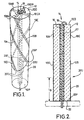
- the other ends of the antenna elements 10A - 10D are connected to a common virtual ground conductor 20 in the form of a plated sleeve surrounding a proximal end portion of the core 12.
- This sleeve 20 is in turn connected to the lining 16 of the axial passage 14 by plating 22 on the proximal end face 12P of the core 12.
- the four longitudinally extending elements 10A - 10D are of different lengths, two of the elements 10B, 10D being longer than the other two 10A, 10C by virtue of extending nearer the proximal end of the core 12.
- the elements of each pair 10A, 10C; 10B, 10D are diametrically opposite each other on opposite sides of the core axis.
- each element follows a simple helical path. Since each of the elements 10A - 10D subtends the same angle of rotation at the core axis, here 180° or a half turn, the screw pitch of the long elements 10B, 10D is steeper than that of the short elements 10A, 10C.
- the upper linking edge 20U of the sleeve 20 is of varying height (i.e. varying distance from the proximal end face 12P) to provide points of connection for the long and short elements respectively. This means that the linking edge 20U follows a non-planar path around the core 12.
- the linking edge 20U follows a zig-zag path around the core 12, having two peaks 20P and two troughs 20T where it meets the short elements 10A, 10C and long elements 10B, 10D respectively.
- Each pair of longitudinally extending and corresponding radial elements constitutes a conductor having a predetermined electrical length.
- the total length of each of the element pairs 10A, 10AR; 10C, 10CR having the shorter length corresponds to a transmission delay of approximately 135° at the operating wavelength
- each of the element pairs 10B, 10BR; 10D, 10DR produce a longer delay, corresponding to substantially 225°.
- the average transmission delay is 180°, equivalent to an electrical length of ⁇ /2 at the operating wavelength.
- the differing lengths produce the required phase shift conditions for a quadrifilar helix antenna for circularly polarised signals specified in Kilgus, "Resonant Quadrifilar Helix Design", The Microwave Journal, Dec. 1970, pages 49-54.
- Two of the element pairs 10C, 10CR; 10D, 10DR i.e. one long element pair and one short element pair
- the radial elements of the other two element pairs 10A, 10AR; 10B, 10BR are connected to the feeder screen formed by metallic lining 16.
- the signals present on the inner conductor 18 and the feeder screen 16 are approximately balanced so that the antenna elements are connected to an approximately balanced source or load, as will be explained below.
- the antenna With the left handed sense of the helical paths of the longitudinally extending elements 10A - 10D, the antenna has its highest gain for right hand circularly polarised signals.
- the longitudinally extending elements can be arranged to follow paths which are generally parallel to the axis.
- the conductive sleeve 20 covers a proximal portion of the antenna core 12, thereby surrounding the feeder structure 16, 18, with the material of the core 12 filling the whole of the space between the sleeve 20 and the metallic lining 16 of the axial passage 14.
- the sleeve 20 forms a cylinder having an average axial length l B as show in Figure 2 and is connected to the lining 16 by the plating 22 of the proximal end face 12P of the core 12.
- the combination of the sleeve 20 and plating 22 forms a balun so that signals in the transmission line formed by the feeder structure 16, 18 are converted between an unbalanced state at the proximal end of the antenna and an approximately balanced state at an axial position generally at the same distance from the proximal end as the upper linking edge 20U of the sleeve 20.
- the average sleeve length l B is such that, in the presence of an underlying core material of relatively high relative dielectric constant, the balun has an average electrical length of ⁇ /4 at the operating frequency of the antenna.
- the feeder structure distally of the sleeve 20 has a short electrical length. Consequently, signals at the distal end of the feeder structure 16, 18 are at least approximately balanced.
- the dielectric constant of the insulation in a semi-rigid cable is typically much lower than that of the ceramic core material referred to above. For example, the relative dielectric constant ⁇ r of PTFE is about 2.2.
- the applicants have found that the variation in length of the sleeve 20 from the mean electrical length of ⁇ /4 has a comparatively insignificant effect on the performance of the antenna.
- the trap formed by the sleeve 20 provides an annular path along the linking edge 20U for currents between the elements 10A - 10D, effectively forming two loops, the first with short elements 10A, 10C and the second with the long elements 10B, 10D.
- current maxima exist at the ends of the elements 10A - 10D and in the linking edge 20U, and voltage maxima at a level approximately midway between the edge 20U and the distal end of the antenna.
- the edge 20U is effectively isolated from the ground connector at its proximal edge due to the approximate quarter wavelength trap produced by the sleeve 20.
- the antenna has a main resonant frequency of 500 MHz or greater, the resonant frequency being determined by the effective electrical lengths of the antenna elements and, to a lesser degree, by their width.
- the lengths of the elements, for a given frequency of resonance, are also dependent on the relative dielectric constant of the core material, the dimensions of the antenna being substantially reduced with respect to an air-cored similarly constructed antenna.
- an antenna as described above for L-band GPS reception at 1575 MHz typically has a core diameter of about 5mm and the longitudinally extending antenna elements 10A - 10D have an average longitudinal extent (i.e. parallel to the central axis) of about 16mm.
- the long elements 10B, 10D are about 1.5mm longer than the short elements 10A, 10C.
- the width of the elements 10A - 10D is about 0.3mm.
- the length of the sleeve 22 is typically in the region of 8mm. Precise dimensions of the antenna elements 10A - 10D can be determined in the design stage on a trial and error basis by undertaking eigenvalue delay measurements until the required phase difference is obtained.
Landscapes
- Details Of Aerials (AREA)
- Support Of Aerials (AREA)
- Burglar Alarm Systems (AREA)
- Variable-Direction Aerials And Aerial Arrays (AREA)
Claims (13)
- Antenne zum Betrieb bei Frequenzen über 200 MHz, umfassend einen im wesentlichen zylindrischen, elektrisch isolierenden Kern (12) aus einem Material mit einer relativen Dielektrizitätskonstanten größer als 5, wobei das Material des Kerns den größten Teil des durch die äußere Kernoberfläche festgelegten Volumens einnimmt, mit einer sich axial durch den Kern erstreckenden Speisestruktur (16 - 18), einer Falle in Form eines leitfähigen, den Kern teilweise umgebenden Sperrtopfs (20) mit einer Masseverbindung an einer Kante und mit einem ersten und zweiten Paar (10A, 10C; 10B, 10D) von Antennenelementen, welche jeweils an einem Ende mit der Speisestruktur verbunden sind und an dem anderen Ende an eine Verbindungskante (20U) des Sperrtopfs, wobei die Antennenelemente (10B, 10D) des zweiten Paars länger sind als die (10A, 10C) des ersten Paars, und die Antennenelemente beider Paare entsprechenden, sich längs erstreckenden Pfaden folgen, dadurch gekennzeichnet, dass die Verbindungskante (20U) einem nicht planaren Pfad um den Kern (12) folgt, wobei die Antennenelemente (10A, 10C) des ersten Paars mit der Verbindungskante an Punkten (20P) verbunden sind, welche näher zu den Verbindungen der Antennenelemente an der Speisestruktur als die Punkte (20T) liegen, bei welchen die Antennenelemente des zweiten Paars mit der Verbindungskante verbunden sind.
- Antenne nach Anspruch 1, dadurch gekennzeichnet, dass jede der sich längs erstreckenden Antennenelemente (10A - 10D) einem jeweiligen schraubenförmigen Pfad um die Achse des Kerns (12) folgt und der Winkel gegenüberliegend an den zwei jeweiligen Enden eines jeden Antennenelementes an der Kernachse der gleiche ist für jedes Antennenelement (10A - 10D).
- Antenne nach Anspruch 2, dadurch gekennzeichnet, dass die Antennenelemente (10A - 10D) eine halbe Umdrehung um die Kernachse ausführen, wobei die Verbindungen zwischen den Antennenelementen und der Speisestruktur (16 - 18) in einer gemeinsamen Ebene senkrecht zur Kernachse liegen, und wobei die Gewindesteigung der Antennenelemente (19B - 10D) des ersten Paars unterschiedlich zu der der Elemente des zweiten Paars sind.
- Antenne nach einem der vorstehenden Ansprüche, dadurch gekennzeichnet, dass die Verbindungskante (20U) des Sperrtopfs (20) einem Zick-Zack-Pfad um den Kern (12) folgt, wobei die Antennenelemente (10A - 10D) des ersten und zweiten Paars an Spitzen (20P) beziehungsweise Senken (20T) der Verbindungskante (20U) verbunden sind.
- Antenne nach einem der vorstehenden Ansprüche, dadurch gekennzeichnet, dass die Massenverbindungskante der Falle in einer Ebene senkrecht zur Kernachse liegt und die mittlere axiale Länge des Sperrtopfs (20) derartig ist, dass die Falle eine elektrische Länge von λ/4 oder ungefähr λ/4 besitzt, wobei λ die Betriebswellenlänge an der Grenzfläche zwischen Luft und dem dielektrischen Material des Kerns (12) ist.
- Antenne nach einem der vorstehenden Ansprüche, dadurch gekennzeichnet, dass die Antenne quadrifilar ist und ein einzelnes erstes Paar und ein einzelnes zweites Paar von Antennenelementen (10A - 10D) besitzt.
- Antenne nach einem der vorstehenden Ansprüche, dadurch gekennzeichnet, dass die Falle und die Antennenelemente (10A - 10D) integral an der zylindrischen äußeren Oberfläche des Kerns (12) gebildet sind.
- Antenne nach einem der vorstehenden Ansprüche, dadurch gekennzeichnet, dass die Antennenelemente (10A - 10D) des ersten und zweiten Paars durch jeweilige radiale Elemente (10AR - 10DR) an einer planaren Endfläche (12D) des Kerns (12) mit der Speisestruktur (16 - 18) verbunden sind, und dass die Masseverbindung der Falle durch eine an der anderen Endfläche (12P) des Kerns gestaltete leitfähige Schicht (22) gebildet ist.
- Antenne nach Anspruch 8, dadurch gekennzeichnet, dass die Speisestruktur (16 - 18) eine koaxiale Übertragungsleitung ist und jedes der Antennenelementenpaare ein Antennenelement (10C; 10D) aufweist, das mit dem inneren Leiter (18) der Speisestruktur verbunden ist und ein Antennenelement (10A; 10B), das mit einem äußeren Leiter (16) der Speisestruktur verbunden ist, und dass der äußere Leiter mit der leitfähigen Schicht (22) verbunden ist.
- Antenne nach einem der vorstehenden Ansprüche, dadurch gekennzeichnet, dass die mittlere Längserstreckung der Antennenelemente (10A - 10D) größer ist als die mittlere axiale Länge des leitfähigen Sperrtopfs (20).
- Antenne nach Anspruch 10, dadurch gekennzeichnet, dass die mittlere axiale Länge der Antennenelemente wenigstens ungefähr zweimal der mittleren axialen Länge des Sperrtopfs (20) ist, und der Durchmesser der Antennenelemente (10A - 10D) und der Durchmesser des Sperrtopfs (20) gleich ist und im Bereich von 0,15 bis 0,25 mal der kombinierten Länge der Antennenelemente und des Sperrtopfs ist.
- Antenne nach Anspruch 10, dadurch gekennzeichnet, dass das Verhältnis der mittleren axialen Länge der Antennenelemente (10A - 10D) zu der mittleren axialen Länge des Sperrtopfs (20) kleiner gleich oder gleich 1:0,35 ist.
- Antenne nach einem der vorstehenden Ansprüche, dadurch gekennzeichnet, dass der Unterschied in der axialen Länge zwischen den Antennenelementen (10A, 10C) des ersten Paars und denen (10B, 10D) des zweiten Paars kleiner als die Hälfte von deren mittleren Länge ist.
Applications Claiming Priority (2)
| Application Number | Priority Date | Filing Date | Title |
|---|---|---|---|
| GB9603914 | 1996-02-23 | ||
| GBGB9603914.4A GB9603914D0 (en) | 1996-02-23 | 1996-02-23 | An antenna |
Publications (3)
| Publication Number | Publication Date |
|---|---|
| EP0791978A2 EP0791978A2 (de) | 1997-08-27 |
| EP0791978A3 EP0791978A3 (de) | 1998-04-01 |
| EP0791978B1 true EP0791978B1 (de) | 2004-08-25 |
Family
ID=10789320
Family Applications (1)
| Application Number | Title | Priority Date | Filing Date |
|---|---|---|---|
| EP97301005A Expired - Lifetime EP0791978B1 (de) | 1996-02-23 | 1997-02-17 | Antenne |
Country Status (10)
| Country | Link |
|---|---|
| US (1) | US5859621A (de) |
| EP (1) | EP0791978B1 (de) |
| JP (1) | JP3489775B2 (de) |
| KR (1) | KR100348441B1 (de) |
| AT (1) | ATE274755T1 (de) |
| CA (1) | CA2198318C (de) |
| DE (1) | DE69730369T2 (de) |
| ES (1) | ES2224204T3 (de) |
| GB (2) | GB9603914D0 (de) |
| MX (1) | MX9701299A (de) |
Cited By (1)
| Publication number | Priority date | Publication date | Assignee | Title |
|---|---|---|---|---|
| US9865914B2 (en) | 2013-01-31 | 2018-01-09 | Hewlett-Packard Development Company, L.P. | Multi-position display deck and antenna |
Families Citing this family (100)
| Publication number | Priority date | Publication date | Assignee | Title |
|---|---|---|---|---|
| GB9417450D0 (en) | 1994-08-25 | 1994-10-19 | Symmetricom Inc | An antenna |
| FR2751137B1 (fr) * | 1996-07-10 | 1998-11-06 | Centre Nat Etd Spatiales | Dispositif d'emission a antenne omnidirectionnelle |
| US6184845B1 (en) | 1996-11-27 | 2001-02-06 | Symmetricom, Inc. | Dielectric-loaded antenna |
| US5896113A (en) * | 1996-12-20 | 1999-04-20 | Ericsson Inc. | Quadrifilar helix antenna systems and methods for broadband operation in separate transmit and receive frequency bands |
| US5920292A (en) * | 1996-12-20 | 1999-07-06 | Ericsson Inc. | L-band quadrifilar helix antenna |
| US5909196A (en) * | 1996-12-20 | 1999-06-01 | Ericsson Inc. | Dual frequency band quadrifilar helix antenna systems and methods |
| GB9722766D0 (en) | 1997-10-28 | 1997-12-24 | British Telecomm | Portable computers |
| US6222505B1 (en) * | 1997-12-03 | 2001-04-24 | Mitsubishi Denki Kabushiki Kaisha | Composite antenna apparatus |
| SE514546C2 (sv) | 1998-05-18 | 2001-03-12 | Allgon Ab | Ett antennsystem och en radiokommunikationsanordning innefattande ett antennsystem |
| GB9813002D0 (en) | 1998-06-16 | 1998-08-12 | Symmetricom Inc | An antenna |
| GB9828768D0 (en) | 1998-12-29 | 1999-02-17 | Symmetricom Inc | An antenna |
| US6169523B1 (en) * | 1999-01-13 | 2001-01-02 | George Ploussios | Electronically tuned helix radiator choke |
| GB9902765D0 (en) | 1999-02-08 | 1999-03-31 | Symmetricom Inc | An antenna |
| WO2000069022A1 (fr) * | 1999-05-07 | 2000-11-16 | Furuno Electric Co., Ltd. | Antenne a polarisation circulaire |
| GB2383901B (en) * | 1999-05-27 | 2003-12-31 | Sarantel Ltd | An antenna |
| GB9912441D0 (en) | 1999-05-27 | 1999-07-28 | Symmetricon Inc | An antenna |
| GB2356086B (en) | 1999-11-05 | 2003-11-05 | Symmetricom Inc | Antenna manufacture |
| JP2001345628A (ja) * | 2000-06-02 | 2001-12-14 | Mitsumi Electric Co Ltd | ヘリカルアンテナおよびその製造方法、並びにその共振周波数調整方法 |
| US6331836B1 (en) | 2000-08-24 | 2001-12-18 | Fast Location.Net, Llc | Method and apparatus for rapidly estimating the doppler-error and other receiver frequency errors of global positioning system satellite signals weakened by obstructions in the signal path |
| JP2002151926A (ja) * | 2000-10-02 | 2002-05-24 | Emtac Technology Corp | アンテナ |
| US6628234B2 (en) | 2001-07-18 | 2003-09-30 | Fast Location.Net, Llc | Method and system for processing positioning signals in a stand-alone mode |
| US6515620B1 (en) | 2001-07-18 | 2003-02-04 | Fast Location.Net, Llc | Method and system for processing positioning signals in a geometric mode |
| US9052374B2 (en) | 2001-07-18 | 2015-06-09 | Fast Location.Net, Llc | Method and system for processing positioning signals based on predetermined message data segment |
| US6529160B2 (en) | 2001-07-18 | 2003-03-04 | Fast Location.Net, Llc | Method and system for determining carrier frequency offsets for positioning signals |
| US6882309B2 (en) | 2001-07-18 | 2005-04-19 | Fast Location. Net, Llc | Method and system for processing positioning signals based on predetermined message data segment |
| US8749054B2 (en) | 2010-06-24 | 2014-06-10 | L. Pierre de Rochemont | Semiconductor carrier with vertical power FET module |
| GB2399948B (en) * | 2003-03-28 | 2006-06-21 | Sarantel Ltd | A dielectrically-loaded antenna |
| US7372427B2 (en) * | 2003-03-28 | 2008-05-13 | Sarentel Limited | Dielectrically-loaded antenna |
| GB0505771D0 (en) * | 2005-03-21 | 2005-04-27 | Sarantel Ltd | Dielectrically-loaded antenna |
| WO2006011723A1 (en) * | 2004-07-28 | 2006-02-02 | Sk Telecom Co., Ltd. | Quadrifilar helical antenna |
| KR100793646B1 (ko) | 2004-07-28 | 2008-01-11 | 스카이크로스 인코포레이티드 | 핸드셋 쿼드리파일러 나선형 안테나 기계적 구조들 |
| US7245268B2 (en) * | 2004-07-28 | 2007-07-17 | Skycross, Inc. | Quadrifilar helical antenna |
| WO2006039699A2 (en) | 2004-10-01 | 2006-04-13 | De Rochemont L Pierre | Ceramic antenna module and methods of manufacture thereof |
| GB0422179D0 (en) | 2004-10-06 | 2004-11-03 | Sarantel Ltd | Antenna feed structure |
| GB2420230B (en) * | 2004-11-11 | 2009-06-03 | Sarantel Ltd | A dielectrically-loaded antenna |
| CN100574006C (zh) * | 2004-12-17 | 2009-12-23 | 宏达国际电子股份有限公司 | 螺旋式天线及螺旋式天线的制造方法 |
| US7253787B2 (en) | 2004-11-25 | 2007-08-07 | High Tech Computer, Corp. | Helix antenna and method for manufacturing the same |
| WO2006136810A1 (en) | 2005-06-21 | 2006-12-28 | Sarantel Limited | An antenna and an antenna feed structure |
| US8350657B2 (en) | 2005-06-30 | 2013-01-08 | Derochemont L Pierre | Power management module and method of manufacture |
| EP1964159A4 (de) | 2005-06-30 | 2017-09-27 | L. Pierre De Rochemont | Elektrische komponenten und verfahren zur herstellung |
| KR100746733B1 (ko) | 2005-10-19 | 2007-08-06 | (주) 한맥 Eng | 듀얼 폴디드 다이폴형 헤리컬 안테나를 이용한 리더기 |
| US7342554B2 (en) * | 2005-11-25 | 2008-03-11 | Inpaq Technology Co., Ltd. | Column antenna apparatus and a manufacturing method thereof |
| US8354294B2 (en) | 2006-01-24 | 2013-01-15 | De Rochemont L Pierre | Liquid chemical deposition apparatus and process and products therefrom |
| GB2437998B (en) | 2006-05-12 | 2009-11-11 | Sarantel Ltd | An antenna system |
| GB2441566A (en) | 2006-09-06 | 2008-03-12 | Sarantel Ltd | An antenna and its feed structure |
| GB2442998B (en) * | 2006-10-20 | 2010-01-06 | Sarantel Ltd | A dielectrically-loaded antenna |
| GB0623774D0 (en) * | 2006-11-28 | 2007-01-10 | Sarantel Ltd | An Antenna Assembly Including a Dielectrically Loaded Antenna |
| GB2444750B (en) | 2006-12-14 | 2010-04-21 | Sarantel Ltd | An antenna arrangement |
| GB2444749B (en) * | 2006-12-14 | 2009-11-18 | Sarantel Ltd | A radio communication system |
| GB2449837B (en) * | 2006-12-20 | 2011-09-07 | Sarantel Ltd | A dielectrically-loaded antenna |
| GB0700276D0 (en) | 2007-01-08 | 2007-02-14 | Sarantel Ltd | A dielectrically-loaded antenna |
| US20080179275A1 (en) * | 2007-01-27 | 2008-07-31 | Kurt Himmelsbach | Cap for an NMR sample tube with inner sealing lip |
| KR100821981B1 (ko) * | 2007-02-02 | 2008-04-15 | 이성철 | 무지향성 안테나 |
| JP4290744B2 (ja) * | 2007-03-12 | 2009-07-08 | 株式会社日本自動車部品総合研究所 | アンテナ装置 |
| US7589694B2 (en) * | 2007-04-05 | 2009-09-15 | Shakespeare Company, Llc | Small, narrow profile multiband antenna |
| JP4943298B2 (ja) * | 2007-11-02 | 2012-05-30 | 日本アンテナ株式会社 | ヘリカルアンテナ |
| GB0724157D0 (en) * | 2007-12-11 | 2008-01-23 | Pilkington Automotive D Gmbh | Antenna |
| US8089421B2 (en) | 2008-01-08 | 2012-01-03 | Sarantel Limited | Dielectrically loaded antenna |
| US7959598B2 (en) | 2008-08-20 | 2011-06-14 | Asante Solutions, Inc. | Infusion pump systems and methods |
| GB0815306D0 (en) | 2008-08-21 | 2008-09-24 | Sarantel Ltd | An antenna and a method of manufacturing an antenna |
| GB0904307D0 (en) | 2009-03-12 | 2009-04-22 | Sarantel Ltd | A dielectrically-loaded antenna |
| WO2010103264A1 (en) | 2009-03-12 | 2010-09-16 | Sarantel Limited | A dielectrically loaded antenna |
| US8106846B2 (en) * | 2009-05-01 | 2012-01-31 | Applied Wireless Identifications Group, Inc. | Compact circular polarized antenna |
| US8456375B2 (en) | 2009-05-05 | 2013-06-04 | Sarantel Limited | Multifilar antenna |
| US8922347B1 (en) | 2009-06-17 | 2014-12-30 | L. Pierre de Rochemont | R.F. energy collection circuit for wireless devices |
| US8952858B2 (en) | 2009-06-17 | 2015-02-10 | L. Pierre de Rochemont | Frequency-selective dipole antennas |
| US8618998B2 (en) | 2009-07-21 | 2013-12-31 | Applied Wireless Identifications Group, Inc. | Compact circular polarized antenna with cavity for additional devices |
| GB2477289B (en) * | 2010-01-27 | 2014-08-13 | Harris Corp | A radio communication apparatus having improved resistance to common mode noise |
| US8552708B2 (en) | 2010-06-02 | 2013-10-08 | L. Pierre de Rochemont | Monolithic DC/DC power management module with surface FET |
| US9023493B2 (en) | 2010-07-13 | 2015-05-05 | L. Pierre de Rochemont | Chemically complex ablative max-phase material and method of manufacture |
| CN103180955B (zh) | 2010-08-23 | 2018-10-16 | L·皮尔·德罗什蒙 | 具有谐振晶体管栅极的功率场效应晶体管 |
| EP2636069B1 (de) | 2010-11-03 | 2021-07-07 | L. Pierre De Rochemont | Halbleiterchip mit trägern mit monolithisch integrierten quantumspunktvorrichtungen und herstellungsverfahren dafür |
| GB201108016D0 (en) | 2011-05-13 | 2011-06-29 | Sarantel Ltd | An antenna and a method of manufacture thereof |
| GB201109000D0 (en) | 2011-05-24 | 2011-07-13 | Sarantel Ltd | A dielectricaly loaded antenna |
| GB201118159D0 (en) | 2011-10-20 | 2011-11-30 | Sarantel Ltd | Radiofrequency circuit assembly |
| GB201120466D0 (en) | 2011-11-25 | 2012-01-11 | Sarantel Ltd | An antenna |
| GB2508638B (en) * | 2012-12-06 | 2016-03-16 | Harris Corp | A dielectrically loaded multifilar antenna with a phasing ring feed |
| US9478850B2 (en) * | 2013-05-23 | 2016-10-25 | Duracell U.S. Operations, Inc. | Omni-directional antenna for a cylindrical body |
| US9561324B2 (en) | 2013-07-19 | 2017-02-07 | Bigfoot Biomedical, Inc. | Infusion pump system and method |
| EP3374905A1 (de) | 2016-01-13 | 2018-09-19 | Bigfoot Biomedical, Inc. | Benutzerschnittstelle für diabetesmanagementsystem |
| WO2017123703A2 (en) | 2016-01-14 | 2017-07-20 | Bigfoot Biomedical, Inc. | Occlusion resolution in medication delivery devices, systems, and methods |
| US10307538B2 (en) | 2016-01-14 | 2019-06-04 | Bigfoot Biomedical, Inc. | Adjusting insulin delivery rates |
| US12383166B2 (en) | 2016-05-23 | 2025-08-12 | Insulet Corporation | Insulin delivery system and methods with risk-based set points |
| EP3646905B1 (de) | 2016-05-26 | 2021-06-23 | Insulet Corporation | Vorrichtung zur abgabe von arzneimitteln in einzeldosis |
| WO2018111928A1 (en) | 2016-12-12 | 2018-06-21 | Mazlish Bryan | Alarms and alerts for medication delivery devices and related systems and methods |
| US10758675B2 (en) | 2017-01-13 | 2020-09-01 | Bigfoot Biomedical, Inc. | System and method for adjusting insulin delivery |
| US10500334B2 (en) | 2017-01-13 | 2019-12-10 | Bigfoot Biomedical, Inc. | System and method for adjusting insulin delivery |
| EP3568860B1 (de) | 2017-01-13 | 2025-12-10 | Insulet Corporation | Insulinverabreichungsverfahren, -systeme und -vorrichtungen |
| WO2018132754A1 (en) | 2017-01-13 | 2018-07-19 | Mazlish Bryan | System and method for adjusting insulin delivery |
| WO2018132765A1 (en) | 2017-01-13 | 2018-07-19 | Mazlish Bryan | Insulin delivery methods, systems and devices |
| USD874471S1 (en) | 2017-06-08 | 2020-02-04 | Insulet Corporation | Display screen with a graphical user interface |
| USD928199S1 (en) | 2018-04-02 | 2021-08-17 | Bigfoot Biomedical, Inc. | Medication delivery device with icons |
| USD920343S1 (en) | 2019-01-09 | 2021-05-25 | Bigfoot Biomedical, Inc. | Display screen or portion thereof with graphical user interface associated with insulin delivery |
| CN110247169B (zh) * | 2019-06-27 | 2020-07-28 | 大连海事大学 | 一种具有宽波束特性的双频四臂螺旋天线 |
| USD977502S1 (en) | 2020-06-09 | 2023-02-07 | Insulet Corporation | Display screen with graphical user interface |
| JP7663693B2 (ja) | 2020-12-18 | 2025-04-16 | インスレット コーポレイション | 薬物送達デバイスの、スマートウォッチおよび車両用インフォテインメントシステムとの統合 |
| US12514980B2 (en) | 2021-06-30 | 2026-01-06 | Insulet Corporation | Adjustment of medicament delivery by a medicament delivery device based on menstrual cycle phase |
| US12521486B2 (en) | 2021-07-16 | 2026-01-13 | Insulet Corporation | Method for modification of insulin delivery during pregnancy in automatic insulin delivery systems |
| CN113675598A (zh) * | 2021-08-23 | 2021-11-19 | 长春理工大学 | 一种四臂螺旋天线 |
| CN120457493A (zh) | 2023-01-06 | 2025-08-08 | 英赛罗公司 | 自动或手动启动的随餐推注输送及随后的自动安全约束放宽 |
Family Cites Families (57)
| Publication number | Priority date | Publication date | Assignee | Title |
|---|---|---|---|---|
| US2575377A (en) * | 1945-11-13 | 1951-11-20 | Robert J Wohl | Short wave antenna |
| US2763003A (en) * | 1953-07-01 | 1956-09-11 | Edward F Harris | Helical antenna construction |
| GB762415A (en) * | 1954-06-17 | 1956-11-28 | Emi Ltd | Improvements in or relating to aerials |
| GB840850A (en) * | 1955-07-19 | 1960-07-13 | Telefunken Gmbh | Improvements relating to high frequency aerial-arrangements |
| US3633210A (en) * | 1967-05-26 | 1972-01-04 | Philco Ford Corp | Unbalanced conical spiral antenna |
| CH499888A (fr) * | 1967-12-15 | 1970-11-30 | Onera (Off Nat Aerospatiale) | Antenne à un seul conducteur enroulé hélicoïdalement de dimensions réduites, et procédé pour sa fabrication |
| US3906509A (en) * | 1974-03-11 | 1975-09-16 | Raymond H Duhamel | Circularly polarized helix and spiral antennas |
| US3940772A (en) * | 1974-11-08 | 1976-02-24 | Rca Corporation | Circularly polarized, broadside firing tetrahelical antenna |
| US4008479A (en) * | 1975-11-03 | 1977-02-15 | Chu Associates, Inc. | Dual-frequency circularly polarized spiral antenna for satellite navigation |
| US4160979A (en) * | 1976-06-21 | 1979-07-10 | National Research Development Corporation | Helical radio antennae |
| US4114164A (en) * | 1976-12-17 | 1978-09-12 | Transco Products, Inc. | Broadband spiral antenna |
| US4204212A (en) * | 1978-12-06 | 1980-05-20 | The United States Of America As Represented By The Secretary Of The Army | Conformal spiral antenna |
| US4323900A (en) * | 1979-10-01 | 1982-04-06 | The United States Of America As Represented By The Secretary Of The Navy | Omnidirectional microstrip antenna |
| US4349824A (en) * | 1980-10-01 | 1982-09-14 | The United States Of America As Represented By The Secretary Of The Navy | Around-a-mast quadrifilar microstrip antenna |
| FR2492540A1 (fr) * | 1980-10-17 | 1982-04-23 | Schlumberger Prospection | Dispositif pour diagraphie electromagnetique dans les forages |
| US4608572A (en) * | 1982-12-10 | 1986-08-26 | The Boeing Company | Broad-band antenna structure having frequency-independent, low-loss ground plane |
| US4608574A (en) * | 1984-05-16 | 1986-08-26 | The United States Of America As Represented By The Secretary Of The Air Force | Backfire bifilar helix antenna |
| US4697192A (en) * | 1985-04-16 | 1987-09-29 | Texas Instruments Incorporated | Two arm planar/conical/helix antenna |
| JPS6330006A (ja) * | 1986-07-23 | 1988-02-08 | Sony Corp | ヘリカルアンテナ |
| JPS6367903A (ja) * | 1986-09-10 | 1988-03-26 | Aisin Seiki Co Ltd | アンテナ装置 |
| GB8624807D0 (en) * | 1986-10-16 | 1986-11-19 | C S Antennas Ltd | Antenna construction |
| SU1483511A1 (ru) * | 1986-12-30 | 1989-05-30 | Организация П/Я В-8942 | Спиральна антенна |
| US4862184A (en) * | 1987-02-06 | 1989-08-29 | George Ploussios | Method and construction of helical antenna |
| GB2202380A (en) * | 1987-03-20 | 1988-09-21 | Philips Electronic Associated | Helical antenna |
| US5081469A (en) * | 1987-07-16 | 1992-01-14 | Sensormatic Electronics Corporation | Enhanced bandwidth helical antenna |
| US5258728A (en) * | 1987-09-30 | 1993-11-02 | Fujitsu Ten Limited | Antenna circuit for a multi-band antenna |
| US5099249A (en) * | 1987-10-13 | 1992-03-24 | Seavey Engineering Associates, Inc. | Microstrip antenna for vehicular satellite communications |
| FR2624656B1 (fr) * | 1987-12-10 | 1990-05-18 | Centre Nat Etd Spatiales | Antenne de type helice et son procede de realisation |
| US4940992A (en) * | 1988-04-11 | 1990-07-10 | Nguyen Tuan K | Balanced low profile hybrid antenna |
| US4980694A (en) * | 1989-04-14 | 1990-12-25 | Goldstar Products Company, Limited | Portable communication apparatus with folded-slot edge-congruent antenna |
| JPH03123203A (ja) * | 1989-10-06 | 1991-05-27 | Harada Ind Co Ltd | 自動車用三波共用アンテナ |
| FR2654554B1 (fr) * | 1989-11-10 | 1992-07-31 | France Etat | Antenne en helice, quadrifilaire, resonnante bicouche. |
| JP2568281B2 (ja) * | 1989-11-17 | 1996-12-25 | 原田工業株式会社 | 自動車用三波共用アンテナ |
| AU643244B2 (en) * | 1990-01-08 | 1993-11-11 | Toyo Communication Equipment Co., Ltd. | 4-wire fractional winding helical antenna and an antenna unit |
| JP2823644B2 (ja) * | 1990-03-26 | 1998-11-11 | 日本電信電話株式会社 | ヘリカルアンテナ |
| GB2246910B (en) * | 1990-08-02 | 1994-12-14 | Polytechnic Electronics Plc | A radio frequency antenna |
| US5198831A (en) * | 1990-09-26 | 1993-03-30 | 501 Pronav International, Inc. | Personal positioning satellite navigator with printed quadrifilar helical antenna |
| JP3185233B2 (ja) * | 1991-03-18 | 2001-07-09 | 株式会社日立製作所 | 携帯無線機用小型アンテナ |
| FI89646C (fi) * | 1991-03-25 | 1993-10-25 | Nokia Mobile Phones Ltd | Antennstav och foerfarande foer dess framstaellning |
| FR2674689B1 (fr) * | 1991-03-29 | 1993-05-21 | Ct Reg Innovat Transfert Tech | Antenne cylindrique imprimee omnidirectionnelle et repondeur radar maritime utilisant de telles antennes. |
| US5346300A (en) * | 1991-07-05 | 1994-09-13 | Sharp Kabushiki Kaisha | Back fire helical antenna |
| JP2719856B2 (ja) * | 1991-07-05 | 1998-02-25 | シャープ株式会社 | バックファイアヘリカルアンテナ |
| US5349365A (en) * | 1991-10-21 | 1994-09-20 | Ow Steven G | Quadrifilar helix antenna |
| CA2061743C (en) * | 1992-02-24 | 1996-05-14 | Peter Charles Strickland | End loaded helix antenna |
| WO1993022804A1 (en) * | 1992-04-24 | 1993-11-11 | Industrial Research Limited | Steerable beam helix antenna |
| JP3209569B2 (ja) * | 1992-05-11 | 2001-09-17 | 原田工業株式会社 | 車両用三波共用アンテナ |
| JP3317521B2 (ja) * | 1992-07-06 | 2002-08-26 | 原田工業株式会社 | 衛星通信用ヘリカルアンテナの製造方法 |
| US5345248A (en) * | 1992-07-22 | 1994-09-06 | Space Systems/Loral, Inc. | Staggered helical array antenna |
| EP0588465A1 (de) * | 1992-09-11 | 1994-03-23 | Ngk Insulators, Ltd. | Keramisches Dielektrikum für Antennen |
| JP2809365B2 (ja) * | 1992-09-28 | 1998-10-08 | エヌ・ティ・ティ移動通信網株式会社 | 携帯無線機 |
| US5485170A (en) * | 1993-05-10 | 1996-01-16 | Amsc Subsidiary Corporation | MSAT mast antenna with reduced frequency scanning |
| JPH07249973A (ja) * | 1994-03-14 | 1995-09-26 | Toshiba Corp | 電子機器 |
| US5479180A (en) * | 1994-03-23 | 1995-12-26 | The United States Of America As Represented By The Secretary Of The Army | High power ultra broadband antenna |
| US5450093A (en) * | 1994-04-20 | 1995-09-12 | The United States Of America As Represented By The Secretary Of The Navy | Center-fed multifilar helix antenna |
| GB2292257B (en) * | 1994-06-22 | 1999-04-07 | Sidney John Branson | An antenna |
| GB9417450D0 (en) * | 1994-08-25 | 1994-10-19 | Symmetricom Inc | An antenna |
| JP3266466B2 (ja) * | 1995-07-26 | 2002-03-18 | 京セラ株式会社 | ヘリカルアンテナ |
-
1996
- 1996-02-23 GB GBGB9603914.4A patent/GB9603914D0/en active Pending
-
1997
- 1997-02-17 AT AT97301005T patent/ATE274755T1/de not_active IP Right Cessation
- 1997-02-17 DE DE69730369T patent/DE69730369T2/de not_active Expired - Lifetime
- 1997-02-17 ES ES97301005T patent/ES2224204T3/es not_active Expired - Lifetime
- 1997-02-17 EP EP97301005A patent/EP0791978B1/de not_active Expired - Lifetime
- 1997-02-17 GB GB9703214A patent/GB2310543B/en not_active Expired - Lifetime
- 1997-02-20 MX MX9701299A patent/MX9701299A/es unknown
- 1997-02-21 US US08/804,209 patent/US5859621A/en not_active Expired - Lifetime
- 1997-02-22 KR KR1019970005437A patent/KR100348441B1/ko not_active Expired - Lifetime
- 1997-02-24 JP JP03932497A patent/JP3489775B2/ja not_active Expired - Lifetime
- 1997-02-24 CA CA002198318A patent/CA2198318C/en not_active Expired - Fee Related
Cited By (1)
| Publication number | Priority date | Publication date | Assignee | Title |
|---|---|---|---|---|
| US9865914B2 (en) | 2013-01-31 | 2018-01-09 | Hewlett-Packard Development Company, L.P. | Multi-position display deck and antenna |
Also Published As
| Publication number | Publication date |
|---|---|
| ATE274755T1 (de) | 2004-09-15 |
| GB9703214D0 (en) | 1997-04-09 |
| GB2310543B (en) | 1999-10-06 |
| ES2224204T3 (es) | 2005-03-01 |
| JPH09246858A (ja) | 1997-09-19 |
| GB2310543A (en) | 1997-08-27 |
| EP0791978A2 (de) | 1997-08-27 |
| CA2198318A1 (en) | 1997-08-24 |
| EP0791978A3 (de) | 1998-04-01 |
| KR970063820A (ko) | 1997-09-12 |
| KR100348441B1 (ko) | 2002-12-02 |
| MX9701299A (es) | 1998-04-30 |
| DE69730369D1 (de) | 2004-09-30 |
| DE69730369T2 (de) | 2005-09-01 |
| US5859621A (en) | 1999-01-12 |
| CA2198318C (en) | 2002-10-08 |
| JP3489775B2 (ja) | 2004-01-26 |
| GB9603914D0 (en) | 1996-04-24 |
Similar Documents
| Publication | Publication Date | Title |
|---|---|---|
| EP0791978B1 (de) | Antenne | |
| EP1153458B1 (de) | Wendelantenne für frequenzen über 200 mhz | |
| MXPA97001299A (en) | An ant | |
| EP1811601B1 (de) | Antenne | |
| EP1098392B1 (de) | Verfahren zur Herstellung einer Wendelantenne aus vier Leitern und nach diesem Verfahren hergestellte Antenne | |
| GB2326532A (en) | Antenna |
Legal Events
| Date | Code | Title | Description |
|---|---|---|---|
| PUAI | Public reference made under article 153(3) epc to a published international application that has entered the european phase |
Free format text: ORIGINAL CODE: 0009012 |
|
| AK | Designated contracting states |
Kind code of ref document: A2 Designated state(s): AT BE CH DE DK ES FI FR GB GR IE IT LI NL PT SE |
|
| PUAL | Search report despatched |
Free format text: ORIGINAL CODE: 0009013 |
|
| AK | Designated contracting states |
Kind code of ref document: A3 Designated state(s): AT BE CH DE DK ES FI FR GB GR IE IT LI NL PT SE |
|
| 17P | Request for examination filed |
Effective date: 19980930 |
|
| 17Q | First examination report despatched |
Effective date: 20001019 |
|
| RAP1 | Party data changed (applicant data changed or rights of an application transferred) |
Owner name: SARANTEL LIMITED |
|
| RBV | Designated contracting states (corrected) |
Designated state(s): AT BE CH DE DK ES FI FR GR IE IT LI NL PT SE |
|
| GRAP | Despatch of communication of intention to grant a patent |
Free format text: ORIGINAL CODE: EPIDOSNIGR1 |
|
| GRAS | Grant fee paid |
Free format text: ORIGINAL CODE: EPIDOSNIGR3 |
|
| GRAA | (expected) grant |
Free format text: ORIGINAL CODE: 0009210 |
|
| AK | Designated contracting states |
Kind code of ref document: B1 Designated state(s): AT BE CH DE DK ES FI FR GR IE IT LI NL PT SE |
|
| PG25 | Lapsed in a contracting state [announced via postgrant information from national office to epo] |
Ref country code: BE Free format text: LAPSE BECAUSE OF FAILURE TO SUBMIT A TRANSLATION OF THE DESCRIPTION OR TO PAY THE FEE WITHIN THE PRESCRIBED TIME-LIMIT Effective date: 20040825 |
|
| REG | Reference to a national code |
Ref country code: CH Ref legal event code: EP |
|
| REG | Reference to a national code |
Ref country code: IE Ref legal event code: FG4D |
|
| REF | Corresponds to: |
Ref document number: 69730369 Country of ref document: DE Date of ref document: 20040930 Kind code of ref document: P |
|
| REG | Reference to a national code |
Ref country code: CH Ref legal event code: NV Representative=s name: BRAUN & PARTNER PATENT-, MARKEN-, RECHTSANWAELTE |
|
| REG | Reference to a national code |
Ref country code: SE Ref legal event code: TRGR |
|
| PG25 | Lapsed in a contracting state [announced via postgrant information from national office to epo] |
Ref country code: GR Free format text: LAPSE BECAUSE OF FAILURE TO SUBMIT A TRANSLATION OF THE DESCRIPTION OR TO PAY THE FEE WITHIN THE PRESCRIBED TIME-LIMIT Effective date: 20041125 Ref country code: DK Free format text: LAPSE BECAUSE OF FAILURE TO SUBMIT A TRANSLATION OF THE DESCRIPTION OR TO PAY THE FEE WITHIN THE PRESCRIBED TIME-LIMIT Effective date: 20041125 |
|
| PG25 | Lapsed in a contracting state [announced via postgrant information from national office to epo] |
Ref country code: IE Free format text: LAPSE BECAUSE OF NON-PAYMENT OF DUE FEES Effective date: 20050217 |
|
| REG | Reference to a national code |
Ref country code: ES Ref legal event code: FG2A Ref document number: 2224204 Country of ref document: ES Kind code of ref document: T3 |
|
| ET | Fr: translation filed | ||
| PLBE | No opposition filed within time limit |
Free format text: ORIGINAL CODE: 0009261 |
|
| STAA | Information on the status of an ep patent application or granted ep patent |
Free format text: STATUS: NO OPPOSITION FILED WITHIN TIME LIMIT |
|
| 26N | No opposition filed |
Effective date: 20050526 |
|
| REG | Reference to a national code |
Ref country code: IE Ref legal event code: MM4A |
|
| PG25 | Lapsed in a contracting state [announced via postgrant information from national office to epo] |
Ref country code: PT Free format text: LAPSE BECAUSE OF NON-PAYMENT OF DUE FEES Effective date: 20050125 |
|
| PGFP | Annual fee paid to national office [announced via postgrant information from national office to epo] |
Ref country code: ES Payment date: 20100129 Year of fee payment: 14 Ref country code: CH Payment date: 20100223 Year of fee payment: 14 |
|
| PGFP | Annual fee paid to national office [announced via postgrant information from national office to epo] |
Ref country code: IT Payment date: 20100225 Year of fee payment: 14 Ref country code: FR Payment date: 20100223 Year of fee payment: 14 Ref country code: FI Payment date: 20100224 Year of fee payment: 14 |
|
| PGFP | Annual fee paid to national office [announced via postgrant information from national office to epo] |
Ref country code: DE Payment date: 20100219 Year of fee payment: 14 Ref country code: AT Payment date: 20100212 Year of fee payment: 14 |
|
| PGFP | Annual fee paid to national office [announced via postgrant information from national office to epo] |
Ref country code: NL Payment date: 20100225 Year of fee payment: 14 |
|
| PGFP | Annual fee paid to national office [announced via postgrant information from national office to epo] |
Ref country code: SE Payment date: 20100212 Year of fee payment: 14 |
|
| REG | Reference to a national code |
Ref country code: NL Ref legal event code: V1 Effective date: 20110901 |
|
| REG | Reference to a national code |
Ref country code: CH Ref legal event code: PL |
|
| REG | Reference to a national code |
Ref country code: SE Ref legal event code: EUG |
|
| PG25 | Lapsed in a contracting state [announced via postgrant information from national office to epo] |
Ref country code: CH Free format text: LAPSE BECAUSE OF NON-PAYMENT OF DUE FEES Effective date: 20110228 Ref country code: LI Free format text: LAPSE BECAUSE OF NON-PAYMENT OF DUE FEES Effective date: 20110228 |
|
| REG | Reference to a national code |
Ref country code: FR Ref legal event code: ST Effective date: 20111102 |
|
| PG25 | Lapsed in a contracting state [announced via postgrant information from national office to epo] |
Ref country code: FI Free format text: LAPSE BECAUSE OF NON-PAYMENT OF DUE FEES Effective date: 20110217 Ref country code: AT Free format text: LAPSE BECAUSE OF NON-PAYMENT OF DUE FEES Effective date: 20110217 |
|
| PG25 | Lapsed in a contracting state [announced via postgrant information from national office to epo] |
Ref country code: NL Free format text: LAPSE BECAUSE OF NON-PAYMENT OF DUE FEES Effective date: 20110901 Ref country code: IT Free format text: LAPSE BECAUSE OF NON-PAYMENT OF DUE FEES Effective date: 20110217 |
|
| REG | Reference to a national code |
Ref country code: DE Ref legal event code: R119 Ref document number: 69730369 Country of ref document: DE Effective date: 20110901 |
|
| PG25 | Lapsed in a contracting state [announced via postgrant information from national office to epo] |
Ref country code: FR Free format text: LAPSE BECAUSE OF NON-PAYMENT OF DUE FEES Effective date: 20110228 |
|
| REG | Reference to a national code |
Ref country code: ES Ref legal event code: FD2A Effective date: 20120411 |
|
| PG25 | Lapsed in a contracting state [announced via postgrant information from national office to epo] |
Ref country code: ES Free format text: LAPSE BECAUSE OF NON-PAYMENT OF DUE FEES Effective date: 20110218 |
|
| PG25 | Lapsed in a contracting state [announced via postgrant information from national office to epo] |
Ref country code: SE Free format text: LAPSE BECAUSE OF NON-PAYMENT OF DUE FEES Effective date: 20110218 |
|
| PG25 | Lapsed in a contracting state [announced via postgrant information from national office to epo] |
Ref country code: DE Free format text: LAPSE BECAUSE OF NON-PAYMENT OF DUE FEES Effective date: 20110901 |