EP0791976B1 - Concealment and disguisement of antenna structures - Google Patents
Concealment and disguisement of antenna structures Download PDFInfo
- Publication number
- EP0791976B1 EP0791976B1 EP97301141A EP97301141A EP0791976B1 EP 0791976 B1 EP0791976 B1 EP 0791976B1 EP 97301141 A EP97301141 A EP 97301141A EP 97301141 A EP97301141 A EP 97301141A EP 0791976 B1 EP0791976 B1 EP 0791976B1
- Authority
- EP
- European Patent Office
- Prior art keywords
- body portion
- support structure
- antenna
- artificial
- proximate
- Prior art date
- Legal status (The legal status is an assumption and is not a legal conclusion. Google has not performed a legal analysis and makes no representation as to the accuracy of the status listed.)
- Expired - Lifetime
Links
- 241001133760 Acoelorraphe Species 0.000 claims abstract description 28
- 238000004873 anchoring Methods 0.000 claims abstract description 8
- 230000015572 biosynthetic process Effects 0.000 claims description 25
- 238000005755 formation reaction Methods 0.000 claims description 25
- 239000000463 material Substances 0.000 claims description 9
- 238000012423 maintenance Methods 0.000 claims description 7
- 239000010903 husk Substances 0.000 claims description 6
- 238000006073 displacement reaction Methods 0.000 claims description 5
- 238000000034 method Methods 0.000 claims description 5
- 239000004020 conductor Substances 0.000 claims description 3
- 239000004033 plastic Substances 0.000 claims description 3
- 229920003023 plastic Polymers 0.000 claims description 3
- 239000002131 composite material Substances 0.000 claims description 2
- 241000737241 Cocos Species 0.000 description 5
- 229910000831 Steel Inorganic materials 0.000 description 5
- 239000010959 steel Substances 0.000 description 5
- 240000003888 Phoenix reclinata Species 0.000 description 3
- 235000005315 Phoenix reclinata Nutrition 0.000 description 3
- 239000011152 fibreglass Substances 0.000 description 3
- 239000007769 metal material Substances 0.000 description 3
- 230000001413 cellular effect Effects 0.000 description 2
- 239000002184 metal Substances 0.000 description 2
- 125000006850 spacer group Chemical group 0.000 description 2
- 238000003466 welding Methods 0.000 description 2
- 238000005452 bending Methods 0.000 description 1
- 238000009434 installation Methods 0.000 description 1
- 229920001169 thermoplastic Polymers 0.000 description 1
- 239000004416 thermosoftening plastic Substances 0.000 description 1
Images


Classifications
-
- H—ELECTRICITY
- H01—ELECTRIC ELEMENTS
- H01Q—ANTENNAS, i.e. RADIO AERIALS
- H01Q1/00—Details of, or arrangements associated with, antennas
- H01Q1/44—Details of, or arrangements associated with, antennas using equipment having another main function to serve additionally as an antenna, e.g. means for giving an antenna an aesthetic aspect
-
- A—HUMAN NECESSITIES
- A41—WEARING APPAREL
- A41G—ARTIFICIAL FLOWERS; WIGS; MASKS; FEATHERS
- A41G1/00—Artificial flowers, fruit, leaves, or trees; Garlands
- A41G1/001—Artificial flowers, fruit, leaves, or trees; Garlands characterised by their special functions
-
- A—HUMAN NECESSITIES
- A41—WEARING APPAREL
- A41G—ARTIFICIAL FLOWERS; WIGS; MASKS; FEATHERS
- A41G1/00—Artificial flowers, fruit, leaves, or trees; Garlands
- A41G1/007—Artificial trees
Definitions
- THIS INVENTION relates to the concealment and disguisement of antennas. It relates in particular to a support structure for an antenna and to a method of at least partially concealing an antenna.
- Fr-A-1549526 discloses a decorative, indoor television receiver aerial in which decorative elements affixed to antenna members of the aerial.
- a support structure for supporting at least one antenna including:
- the access passage is typically used for maintenance and/or installation purposes. Accordingly, the base may have a lower door at its operatively lower end and an upper door at its operatively upper end, the lower and upper doors being connected by the access passage.
- the base may be made of steel.
- a plurality of steel sections are serially attached to one another, e.g. by welding joints.
- the steel sections are stacked in a telescopic fashion with a friction fit.
- the support structure includes a platform mounted at the upper end of the body portion, access to the platform being provided by the access passage.
- a support structure for supporting at least one antenna including:
- the support structure includes:
- the support structure is in the form of a mast, such as those used, for example, in cellular telecommunications networks.
- support structure should be interpreted broadly to include any structure for supporting an antenna or the like.
- support structure thus includes structures which are not self-supporting such as those that are held in position by guy ropes.
- the anchoring surface is typically the ground and the displacement arrangement is typically a winch, or the like.
- the artificial foliage may resemble branches and/or leaves of a tree.
- the artificial foliage resembles leaf stems and fronds of a palm tree, such as fronds of a Cocos Plumosa, a Phoenix Reclinata, or the like.
- the artificial foliage may also be shaped to resemble a trunk of a tree.
- the artificial foliage of the support structure includes a plurality of elongate components and a plurality of leaf-like formations attached to each elongate component.
- the leaf-like formations are moulded from a synthetic plastics material or the like.
- the support structure includes attachment means for attaching the artificial foliage to the body portion, the attachment means being configured to allow movement of the artificial foliage relative to the body portion.
- the elongated components may be releasably attached to a body portion.
- the attachment means is typically in the form of a clamp configured to clamp onto the body portion.
- the clamp may have a plurality of mounting formations for mounting the elongate components to the clamp.
- the attachment means is in the form of a socket in which an end of the elongate component is receivable.
- the end of the elongate component is receivable.
- the end of the elongate component is receivable.
- the end of the elongate component is potted by means of a rubberised material within the socket.
- the elongate components and the leaf-like formations are made of a flexible, resilient plastics material thereby to permit flexing of the elongate components and the leaf-like formations in a similar fashion to a natural tree.
- each elongated component of the support structure includes a longitudinal internal passage which extends between its ends, and a flexible cord located in the passage to anchor, in the event of the elongate component being broken, a broken segment to the remainder of the elongate component.
- the elongate components are advantageously made of a non-metallic material, such as reinforced fibre glass or the like, thereby to minimise interference with the antenna field.
- the support structure includes holding means to hold each elongate component at a preselected angle relative to the body portion.
- holding means may be provided to hold the elongate component at a preselected angle relative to the body portion.
- the holding means may be configured to hold different preselected figures at different preselected angles.
- Each elongate component may be in cross-section trapezoidal, square, or of any other suitable shape.
- each elongate component and the leaf-like formations of the support structure resemble a frond of a palm tree.
- the artificial leaves may comprise a plurality of leaf-like formations attached to a common spine.
- the leaf-like formations may extend transversely to the spine.
- the leaf-like formations may be arched when viewed in cross section.
- the leaf-like components may also have zones of weakness intermediate their ends to permit the leaf-like formations to be bent at appropriate places during erection.
- a plurality of inner fronds of the support structure extend upwardly relative to the body portion at a relatively small angle thereby to be positioned in close proximity to the antenna so as at least partially to conceal the antenna, and a plurality of outer fronds are arranged to extend operatively upwardly at a greater angle relative to the body portion.
- the support structure includes concealment means for concealing attachment of the artificial foliage to the body portion.
- the concealment means of the support structure is in the form of a plurality of artificial palm tree husks.
- the body portion of the support structure is composite in nature comprising a plurality of hollow frusto-conical sections serially connected.
- the body portion may include a base and a support frame.
- the base may resemble the trunk of a tree e.g. the trunk of a Cocos Plumosa, and is typically painted and/or shaped accordingly.
- the support frame may be mounted in use on top of the base and the antenna may be mounted on the support frame by mounting means. Typically, three antennas are mounted on the support frame so that they face in angularly spaced radial directions.
- the support structure includes a sleeve which is snugly located about the body portion and which is aesthetically configured to resemble the trunk of a natural palm tree.
- the support structure includes a lightning conductor mounted on the upper end of the body portion and which extends in use above the antenna.
- the support structure includes a navigation warning light mounted proximate a terminal end of the support structure.
- a method of at least partially concealing an antenna including a support structure and the support structure including:
- the support structure may include a plurality of windshields for shielding the antenna from the wind.
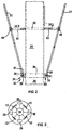
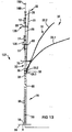
- reference numeral 10 generally indicates a support structure, in accordance with the invention, for supporting one or more antennas 12.
- the support structure 10 includes a body portion 14 (see Figure 1) and artificial foliage 16 attached to the body portion 14 and positioned so as at least partially to conceal the antennas 12.
- the body portion 14 is anchored at its operatively lower end 18 to the ground 20.
- the support structure 10 is in the form of a mast and the antennas 12 are typically three cellular telecommunication network antennas.
- the artificial foliage 16 resembles branches or stems, and leaves of a tree which, in the embodiment depicted in Figures 1 to 10 of the drawings, is in the form of a palm tree such as a Cocos Plumosa. Accordingly, the artificial foliage 16 includes a plurality of elongate components which are in the form of branches or stems 22 which are attached at 24 (see Figures 1 and 2) by a clamp 26 to a base 28 of the body portion 14. Each stem 22 is flexible and resilient and is made of a non-metallic material, such as reinforced fibre glass or the like, thereby to minimise interference with the antenna fields of the antennas 12.
- the stems 22 extend upwardly at an angle relative to the body portion 14 and holding struts 30 (see Figure 2) are provided to hold them at different angles relative to the body portion 14 as is the case with fronds of a normal palm tree.
- Inner artificial foliage generally indicated by reference numeral 32
- Outer artificial foliage generally indicated by reference numeral 34
- the inner artificial foliage 32 may be secured to windshields 36 (see Figure 3) to restrict their movement in the event of strong winds.
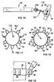
- the clamp 26 has a plurality of mounting formations 40 (see Figure 2) for mounting an operatively lower end 38 of each stem 22 to the clamp 26.
- Each mounting formation 40 comprises two spaced parallel plates 39 having apertures defined therein and the lower end 38 of each stem 22 has a transverse passage defined therein.
- the lower end 38 is located between the spaced plates 39 and secured in position by means of a nut and bolt arrangement 41 .
- a number of holding struts 30 corresponding to the number of stems 22 are provided and each holding strut 30 has a spacing arm 42 which is mounted on the base 28 by means of a common bracket 44.
- a clamp 46 which is shaped and dimensioned to clamp onto the stem 22, is attached to an end of the arm 42 which is distal from its attachment to the bracket 44.
- the arms 42 have varying lengths so that stems 22 attached to different arms 42 are orientated at different angles relative to the base 28.
- Each stem 22 has a central longitudinal passage 48 (see Figure 5 and 6) which extends between its ends.
- a flexible cord 50 (see Figure 6), such as a length of rope, is located in the passage 48 and is attached at its ends to opposed ends of the stem 22. Accordingly, in the event of the stem 22 being broken, a broken segment remains attached to the remaining portion of the stem 22 which is still attached to the base 28.
- the artificial foliage 16 includes a plurality of artificial leaf components 51 (see Figure 7 to 9).
- Each artificial leaf component 51 has a plurality of leaf-like members 52 attached to a common spine 54.
- the leaf-like members 52 extend transversely to the spine 54 and each leaf-like member 52 is triangular when viewed from an end (see Figure 9).
- Zones of weakness or of reduced rigidity 56 are provided to encourage bending of the leaf-like members 52.
- the zones of weakness or of reduced rigidity 56 are located at different positions along a length of each leaf-like member 52 so that they bend at different positions along their length thereby more closely to resemble leaves of a palm tree. The leaf-like members can thus be bent in a random fashion during erection of the structure.
- the stem 22 is generally square in cross-section and, accordingly, the artificial leaf components 51 have matingly shaped mounting formations 58 (see Figures 6 and 8) to facilitate attachment thereof to the stem 22.
- Each shaped mounting formation 58 is defined by the spine 54 and is in the form of an angled bracket which operatively abuts a corner 60 (see Figure 6) of the stem 22.
- a second mounting formation 58 of a further artificial leaf component 51 which extends in an opposite direction, fits snugly in overlapping relationship with the first mounting formation 58 and the two artificial leaf components 51 are then attached to the stem 22 by means of cable ties 62 (see Figure 5).
- the artificial leaf components 51 are arranged so that their upper ridges 64 face operatively upwardly as is the case with the leaves of a natural Cocos Plumosa palm tree.
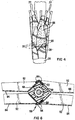
- the support structure 10 includes concealment means in the form of artificial husks 66 (see Figure 4) which are positioned to conceal the lower ends 38 of the stems 22 and the clamp 26.
- the husks 66 are arranged in an overlapping fashion so as to resemble those of a natural palm tree.
- the base 28 is shaped and coloured aesthetically to resemble a trunk of a normal palm tree (see Figure 1). Accordingly, growth lines 68 (only a few of which are referenced) are provided on the base 28.
- the base 28 is typically 20 m in height and has a internal access passage 29, e.g. for maintenance purposes, extending between its ends.
- a lower door 70 is provided at the lower end 18 of the body portion 14 and an internal step ladder (not shown) is provided between the lower end 18 and an upper end 72 of the base 28.
- An upper door (not shown) leads onto a platform 74 (see Figure 1).
- the platform 74 is made of a non-metallic material thereby to reduce interference with the antenna fields.
- the base 28 is formed from a plurality of steel sections which are serially attached to one another by means of welding joints.
- the body portion 14 also has a support frame 76 (see Figures 1 and 10) which defines mounting means for mounting the antennas 12.
- the support frame 76 is mounted on top of the base 28 and a step ladder 78 is mounted thereon to facilitate access to the antennas 12.
- three antennas 12 are attached to the support frame 76 and the antennas 12 are positioned to face outwardly in angularly spaced radial directions.
- the inner artificial foliage 32 is typically attached to the windshields 36 in order to hold their stems 22 in close proximity to the antennas 12.
- the windshields 36 also form protection means for protecting the antennas 12 from the artificial foliage 16 in the event of it being blown around in high wind.
- the stems 22 of the inner foliage 32 are attached by holding means to the frame 76 (see Figure 10) so as to be in close. proximity to the antennas 12.
- the holding means are in the form of a plurality of angled holding loops 80 each of which encircles a stem 22 thereby allowing restricted movement of the stem 22.
- the holding loops 80 also prevent the stems 22 from being blown under windy conditions into contact with the antennas 12.
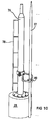
- reference numerals 100 and 102 generally indicate further embodiments of a support structure, in accordance with the invention, for supporting a plurality of antennas 12.
- the support structures 100, 102 resemble the support structure 10 and, accordingly, like reference numerals have been used to indicate the same or similar features unless otherwise indicated.
- the support structure 100 as in the case of the support structure 10, includes a body portion 14 mounted at its lower end 18 to the ground 20.
- the support structure 100 also includes a support frame 76, which is mounted on an upper end 72 of the body portion 14, and which defines mounting means for mounting an antenna 12.
- the support structure 100 includes only attachment means 104 for attaching an operatively lower end 38 of each stem 22, which is in the form of a frond, to the body portion 14.
- the attachment means comprises a plurality of square tubular sockets 106 (only a few of which are referenced in the drawings for the purposes of clarity).
- the sockets 106 are orientated upwardly and obliquely relative to the body portion 14 and are arranged in such a fashion so that the stems 22 are orientated in a similar fashion to a conventional palm tree
- each socket 106 a complemental square tubular plug 108 (see Figure 12) is receivable.
- the square tubular plug 108 has an aperture 110 and each socket 106 has a corresponding aperture (not shown) to permit the plug 108 to be bolted to the socket 106.
- the plug 108 is made of steel and includes an internal passage in which the lower end 38 of the stem 22, is potted with a rubberised material 112 to permit movement between the lower end 38 and the socket 106.
- the stems 22 are typically made of a material such as HOSTALEN GM 9240 H T and are configured so that they resemble the flexibility of a frond of a natural palm tree e.g. typically a Phoenix Reclinata palm tree.
- the support structure 100 is typically about 12 metres in height and does not include an internal access passage as in the case of the support structure 10.
- the attachment means 104 is a displaceable attachment means and a winch arrangement 114 is provided to permit displacement of both the support frame 76 and the attachment means 104 between an operative position (as shown in Figure 11) in which the support frame 76 and the attachment means 104 are located proximate the upper end 72 of the body portion 14, and an inoperative position (not shown) in which the support frame 76 and the attachment means 104 is displaced to the lower end 18 of the body portion 14 thereby to facilitate maintenance of the antenna 12 and/or the artificial foliage 16.
- the body portion 14 includes a fibre glass sleeve 105 (only a portion of which is shown in Figure 11) which is aesthetically configured to resemble the stem of the Phoenix Reclinata palm tree.
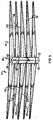
- the support structure 102 resembles the support structure 10 of Figures 1 to 10, but has a different attachment arrangement for attaching the stems 22 to the body portion 14.
- the support structure 102 includes lower and upper clamps 26.1, 26.2 respectively (see Figures 13, 17 to 19).
- the upper clamp 26.2 defines attachment means for attaching operatively lower ends 38 of outer stems 22.1 of the outer artificial foliage 34 to the base 28 of the body portion 14.
- the lower clamp 26. which is located in a spaced relationship at an operatively lower position relative to the upper clamp 26.2, defines attachment means for attaching operatively lower ends 38 of inner stems 22.2 of the outer artificial foliage 34.
- Both the inner and the outer stems 22.2 and 22.1 respectively of the outer artificial foliage 34 have their movement restricted by holding struts 30, as will be described in more detail below.
- the inner and outer stems 22.2 and 22.1 are also typically made of a thermoplastics material such as HOSTALEN GM 9240 HT and are configured so that they resemble the fronds of a Cocos Plumosa palm tree.
- each mounting formation 40 comprises two spaced parallel plates 39 (only a few of which are referenced in Figures 17 and 18 for the sake of clarity) between which an apertured lower end 38 of each stem 22.1 or 22.2 is located, as the case may be.
- a nut and bolt arrangement 41 which passes through corresponding apertures in each plate 39 and the aperture provided in the lower end 38, fixedly attaches each stem 22.1 or 22.2 to an upper or lower clamp 26.2, 26.1, respectively.
- the parallel plates 39 are attached to a common clamp 26 (see Figure 17 to 19) which is clamped to the base 28 of the body portion 14.
- the upper and lower clamps 26.2 and 26.1 are clamped to the base 28 in such a fashion so that unhindered spaces 116 of the upper clamp 26.2 are aligned with the mounting formations 40 of the lower clamp 26.1 so that inner stems 22.2 extending therefrom are not hindered by outer stems 22.1 attached to the upper clamp 26.2.
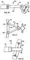
- the holding strut 30 includes a spacing arm 42 which is attached at its one end to a common bracket (not shown) and at its other end to a movable attachment means 118.
- the movable attachment means 118 comprises a clamp 46 which is clamped onto the stem 22, an anchor arrangement 120 which is anchored to the spacing arm 42, and a short chain link 122 which links the clamp 46 and the anchor arrangement 120.
- the anchor arrangement 120 with its chain link 122, permits movement of the stem 22 in all. planes relative to the spacer arm 42 and thus allows the stem 22 to resemble the movement of a frond of a natural palm tree.
- the holding strut 30 may take on various forms to permit relative displacement between the stem 22 and the body portion 14.
- a holding strut 30.1 (depicted in Figures 20 and 22 of the drawings) includes a spacer arm 42 which is in the form of a wishbone arrangement 124.
- the wishbone arrangement 124 is pivoted at 126 and 128 to the common bracket 44, and at 130 to a clamp 46.
- a further embodiment of the holding strut 30.2 includes a spacing arm 42 to which a smooth metal ring 132 is attached.
- the ring 132 includes an inner lining of friction resistant material (not shown) and a further inner lining of a potted rubberised material (not shown) which defines a resilient clamping formation.
- a sleeve 134 is provided on that portion of the stem 22 that extends through the metal ring 132 to protect the stem 22.
- stems 22 which are attached to the body portion 14 proximate the platform 74 define the inner artificial foliage 32.
- the stems 22 of the inner artificial foliage 32 are attached to the body portion 14 in a similar fashion to the stems 22 of the outer artificial foliage 34.
- the inner artificial foliage 32 is held in close proximity to the antennas 12 by holding means 80 (see Figures 13 to 15) which are positioned at upper and lower spaced locations 138, 136, respectively, of the support frame 76.
- a support means 80 is provided for each stem 22 and includes a bracket 140 (see Figure 14 and 15) which is clamped onto the support frame 76.
- a generally square-shaped retaining ring 142 is attached to the bracket 140 and includes a retaining bracket 144 for checking movement of the stem 22.
- a step ladder 146 extends from the platform 74 towards an uppermost end of the support frame 76 which terminates in an aviation warning light 148 (see Figure 13) positioned at an uppermost end of a lightning conductor 150.
- a similar retaining ring 142 is attached to an opposed side of the bracket 142 and extends in an opposed direction to support a further stem 22 of the inner foliage 32.
- Three antennas 12 are mounted in a radially angularly spaced position on the support frame 76.
- attachment of the operatively lower ends 38 of the stems 22 of the support structures 100, 102 are concealed by a plurality of husks 66 (see Figure 4).
- the invention provides a support device 10, 100, 102 for supporting antennas 12 in such a fashion so that the antennas 12 may be at least partially concealed.
- What would normally be a conventional mast is thus disguised as a palm tree and the antennas 12 are at least partially concealed by the artificial foliage 16.
Landscapes
- Engineering & Computer Science (AREA)
- Textile Engineering (AREA)
- Support Of Aerials (AREA)
- Details Of Aerials (AREA)
- Burglar Alarm Systems (AREA)
Abstract
Description
- THIS INVENTION relates to the concealment and disguisement of antennas. It relates in particular to a support structure for an antenna and to a method of at least partially concealing an antenna.
- An example of an antenna support structure for a telecommunications system is disclosed in WO-A1-9516840. Fr-A-1549526 discloses a decorative, indoor television receiver aerial in which decorative elements affixed to antenna members of the aerial.
- According to a first aspect of the invention, there is provided a support structure for supporting at least one antenna , the support structure including:
- an elongate body portion having an upper longitudinal end and a lower longitudinal end and which is anchored in use proximate its lower end to an anchoring surface ; and
- mounting means for mounting the antenna proximate an operatively upper end of the body portion ; characterised by:
- an access passage which extends at least partially between the upper and lower ends of the body portion to provide access to the antenna for maintenance purposes; and
- artificial foliage attached to the body portion and positioned so as at least partially to conceal the antenna.
-
- The access passage is typically used for maintenance and/or installation purposes. Accordingly, the base may have a lower door at its operatively lower end and an upper door at its operatively upper end, the lower and upper doors being connected by the access passage.
- The base may be made of steel. Typically, a plurality of steel sections are serially attached to one another, e.g. by welding joints. In certain embodiments, the steel sections are stacked in a telescopic fashion with a friction fit.
- Preferably, the support structure includes a platform mounted at the upper end of the body portion, access to the platform being provided by the access passage.
- In accordance with a second aspect of the invention, there is provided a support structure for supporting at least one antenna, the support structure including:
- an elongate body portion having an upper longitudinal end and a lower longitudinal end which is anchored in use proximate its lower end to an anchoring surface; and
- mounting means for mounting the antenna proximate an operatively upper end of the body portion; characterised in that:
- the support structure is aesthetically configured to resemble the trunk of a palm tree; and in that:
- artificial foliage which resembles the foliage of a palm tree is attached to the body portion and positioned so as at least partially to conceal the antenna.
-
- Preferably, the support structure includes:
- displaceable attachment means for displaceably attaching the artificial foliage and the mounting means to the body portion; and
- a displacement arrangement which co-operates with the displaceable attachment means to displace the artificial foliage and the mounting means between an operative position in which the artificial foliage and mounting means are proximate the upper end of the body portion, and an inoperative position in which the artificial foliage and mounting means are proximate the lower end of the body portion.
-
- Typically, the support structure is in the form of a mast, such as those used, for example, in cellular telecommunications networks. However, the term "support structure" should be interpreted broadly to include any structure for supporting an antenna or the like. The term "support structure" thus includes structures which are not self-supporting such as those that are held in position by guy ropes. The anchoring surface is typically the ground and the displacement arrangement is typically a winch, or the like.
- Accordingly, the artificial foliage may resemble branches and/or leaves of a tree. Preferably, the artificial foliage resembles leaf stems and fronds of a palm tree, such as fronds of a Cocos Plumosa, a Phoenix Reclinata, or the like. The artificial foliage may also be shaped to resemble a trunk of a tree.
- Preferably, the artificial foliage of the support structure, includes a plurality of elongate components and a plurality of leaf-like formations attached to each elongate component. Typically, the leaf-like formations are moulded from a synthetic plastics material or the like.
- Preferably the support structure includes attachment means for attaching the artificial foliage to the body portion, the attachment means being configured to allow movement of the artificial foliage relative to the body portion. Typically, the elongated components may be releasably attached to a body portion.
- The attachment means is typically in the form of a clamp configured to clamp onto the body portion. The clamp may have a plurality of mounting formations for mounting the elongate components to the clamp. In certain embodiments, the attachment means is in the form of a socket in which an end of the elongate component is receivable. Typically, the end of the elongate component is receivable. Typically, the end of the elongate component is receivable. Typically, the end of the elongate component is potted by means of a rubberised material within the socket.
- Preferably the elongate components and the leaf-like formations are made of a flexible, resilient plastics material thereby to permit flexing of the elongate components and the leaf-like formations in a similar fashion to a natural tree.
- Preferably each elongated component of the support structure includes a longitudinal internal passage which extends between its ends, and a flexible cord located in the passage to anchor, in the event of the elongate component being broken, a broken segment to the remainder of the elongate component.
- The elongate components are advantageously made of a non-metallic material, such as reinforced fibre glass or the like, thereby to minimise interference with the antenna field.
- Preferably, the support structure includes holding means to hold each elongate component at a preselected angle relative to the body portion. Accordingly, holding means may be provided to hold the elongate component at a preselected angle relative to the body portion. Typically, the holding means may be configured to hold different preselected figures at different preselected angles. Each elongate component may be in cross-section trapezoidal, square, or of any other suitable shape.
- Preferably each elongate component and the leaf-like formations of the support structure resemble a frond of a palm tree. The artificial leaves may comprise a plurality of leaf-like formations attached to a common spine. The leaf-like formations may extend transversely to the spine. The leaf-like formations may be arched when viewed in cross section. The leaf-like components may also have zones of weakness intermediate their ends to permit the leaf-like formations to be bent at appropriate places during erection.
- Preferably, a plurality of inner fronds of the support structure extend upwardly relative to the body portion at a relatively small angle thereby to be positioned in close proximity to the antenna so as at least partially to conceal the antenna, and a plurality of outer fronds are arranged to extend operatively upwardly at a greater angle relative to the body portion.
- Preferably, the support structure includes concealment means for concealing attachment of the artificial foliage to the body portion.
- Preferably the concealment means of the support structure is in the form of a plurality of artificial palm tree husks.
- Preferably, the body portion of the support structure is composite in nature comprising a plurality of hollow frusto-conical sections serially connected. The body portion may include a base and a support frame. The base may resemble the trunk of a tree e.g. the trunk of a Cocos Plumosa, and is typically painted and/or shaped accordingly. The support frame may be mounted in use on top of the base and the antenna may be mounted on the support frame by mounting means. Typically, three antennas are mounted on the support frame so that they face in angularly spaced radial directions.
- Preferably, the support structure includes a sleeve which is snugly located about the body portion and which is aesthetically configured to resemble the trunk of a natural palm tree.
- Preferably, the support structure includes a lightning conductor mounted on the upper end of the body portion and which extends in use above the antenna.
- Preferably, the support structure includes a navigation warning light mounted proximate a terminal end of the support structure.
- In accordance with a third aspect of the invention there is provided a method of at least partially concealing an antenna, the antenna including a support structure and the support structure including:
- an elongate body portion having an upper longitudinal end and a lower longitudinal end and which is anchored in use proximate its lower end to an anchoring surface; and
- mounting means for mounting the antenna proximate an operatively upper end of the body portion; characterised in that the method includes providing an access passage which extends at least partially between the upper and lower ends of the body portion to provide access to the antenna for maintenance purposes; and locating a plurality of fronds of an artificial palm tree around at least a portion of the antenna at least partially to conceal the antenna.
-
- The support structure may include a plurality of windshields for shielding the antenna from the wind.
- The invention is now described, by way of example, with reference to the accompanying diagrammatic drawings in which:
- Figure 1 shows a schematic side view of a support structure, in accordance with the invention, for supporting an antenna;
- Figure 2 shows a side view of a portion of the support structure to a larger scale showing attachment of two stems to a base of the structure;
- Figure 3 shows a top view of the support structure, certain detail being omitted for clarity, and showing in particular shields for shielding antennas from the stems;
- Figure 4 shows a side view of a portion of the structure to a larger scale showing husks for concealing attachment of the stems to the base;
- Figure 5 shows a three-dimensional view of a portion of the structure showing artificial leaf components attached to a stem;
- Figure 6 shows a cross-sectional view of four artificial leaf components of Figure 5 attached to a stem;
- Figure 7 shows a top plan view of a single leaf component;
- Figure 8 shows a side view of a single leaf component of Figure 7;
- Figure 9 shows a cross-sectional view of the leaf component of Figure 7 taken at IX-IX;
- Figure 10 shows a schematic three-dimensional view of a holding loop for holding inner artificial foliage in close proximity to the antennas;
- Figure 11 shows a pictorial view of a further embodiment of the support structure, in accordance with the invention, for supporting an antenna;
- Figure 12 shows an exploded view of a branch or stem of the support structure of Figure 11;
- Figure 13 shows a pictorial view of a yet further embodiment of the support structure in accordance with the invention;
- Figure 14 shows a top plan view of a holding loop and a mounting bracket of the support structure of Figure 13;
- Figure 15 shows a side view of the holding loop and the mounting bracket of Figure 14;
- Figure 16 shows a side view of a holding strut for holding a stem of the support structure of Figure 13;
- Figure 17 shows a top plan view of an upper clamp of the support structure of Figure 13;
- Figure 18 shows a top plan view of a lower clamp of the support structure of Figure 13;
- Figure 19 shows a side view of attachment means for attaching a lower end of a stem to either the upper and the lower clamps of Figures 17 and 18;
- Figure 20 shows a side view of a further embodiment of a holding strut used in the support structure of Figure 13;
- Figure 21 shows a top plan view of the holding strut of Figure 20; and
- Figure 22 shows a side view of a yet further embodiment of a holding strut used in the support structure of Figure 13.
-
- In the drawings,
reference numeral 10 generally indicates a support structure, in accordance with the invention, for supporting one ormore antennas 12. Thesupport structure 10 includes a body portion 14 (see Figure 1) andartificial foliage 16 attached to thebody portion 14 and positioned so as at least partially to conceal theantennas 12. Thebody portion 14 is anchored at its operativelylower end 18 to theground 20. Thesupport structure 10 is in the form of a mast and theantennas 12 are typically three cellular telecommunication network antennas. - The
artificial foliage 16 resembles branches or stems, and leaves of a tree which, in the embodiment depicted in Figures 1 to 10 of the drawings, is in the form of a palm tree such as a Cocos Plumosa. Accordingly, theartificial foliage 16 includes a plurality of elongate components which are in the form of branches or stems 22 which are attached at 24 (see Figures 1 and 2) by aclamp 26 to abase 28 of thebody portion 14. Each stem 22 is flexible and resilient and is made of a non-metallic material, such as reinforced fibre glass or the like, thereby to minimise interference with the antenna fields of theantennas 12. - The stems 22 extend upwardly at an angle relative to the
body portion 14 and holding struts 30 (see Figure 2) are provided to hold them at different angles relative to thebody portion 14 as is the case with fronds of a normal palm tree. Inner artificial foliage, generally indicated byreference numeral 32, is arranged to extend upwardly relative to thebody portion 14 at a relatively small angle thereby to be positioned in close proximity to theantennas 12 so as at least partially to conceal theantennas 12. Outer artificial foliage, generally indicated byreference numeral 34, is arranged to extend operatively upwardly at a greater angle relative to thebody portion 14 thereby to resemble outer or less vertically orientated fronds of a palm tree. The innerartificial foliage 32 may be secured to windshields 36 (see Figure 3) to restrict their movement in the event of strong winds. - The
clamp 26 has a plurality of mounting formations 40 (see Figure 2) for mounting an operativelylower end 38 of each stem 22 to theclamp 26. Each mountingformation 40 comprises two spacedparallel plates 39 having apertures defined therein and thelower end 38 of each stem 22 has a transverse passage defined therein. Thelower end 38 is located between the spacedplates 39 and secured in position by means of a nut andbolt arrangement 41 . A number of holding struts 30 corresponding to the number of stems 22 are provided and each holdingstrut 30 has aspacing arm 42 which is mounted on thebase 28 by means of acommon bracket 44. Aclamp 46, which is shaped and dimensioned to clamp onto thestem 22, is attached to an end of thearm 42 which is distal from its attachment to thebracket 44. Thearms 42 have varying lengths so that stems 22 attached todifferent arms 42 are orientated at different angles relative to thebase 28. - Each stem 22 has a central longitudinal passage 48 (see Figure 5 and 6) which extends between its ends. A flexible cord 50 (see Figure 6), such as a length of rope, is located in the
passage 48 and is attached at its ends to opposed ends of thestem 22. Accordingly, in the event of thestem 22 being broken, a broken segment remains attached to the remaining portion of thestem 22 which is still attached to thebase 28. - The
artificial foliage 16 includes a plurality of artificial leaf components 51 (see Figure 7 to 9). Eachartificial leaf component 51 has a plurality of leaf-like members 52 attached to acommon spine 54. The leaf-like members 52 extend transversely to thespine 54 and each leaf-like member 52 is triangular when viewed from an end (see Figure 9). Zones of weakness or of reduced rigidity 56 (only a few of which are shown) are provided to encourage bending of the leaf-like members 52. The zones of weakness or of reducedrigidity 56 are located at different positions along a length of each leaf-like member 52 so that they bend at different positions along their length thereby more closely to resemble leaves of a palm tree. The leaf-like members can thus be bent in a random fashion during erection of the structure. - The
stem 22 is generally square in cross-section and, accordingly, theartificial leaf components 51 have matingly shaped mounting formations 58 (see Figures 6 and 8) to facilitate attachment thereof to thestem 22. Each shaped mountingformation 58 is defined by thespine 54 and is in the form of an angled bracket which operatively abuts a corner 60 (see Figure 6) of thestem 22. A second mountingformation 58 of a furtherartificial leaf component 51, which extends in an opposite direction, fits snugly in overlapping relationship with the first mountingformation 58 and the twoartificial leaf components 51 are then attached to thestem 22 by means of cable ties 62 (see Figure 5). Theartificial leaf components 51 are arranged so that theirupper ridges 64 face operatively upwardly as is the case with the leaves of a natural Cocos Plumosa palm tree. - The
support structure 10 includes concealment means in the form of artificial husks 66 (see Figure 4) which are positioned to conceal the lower ends 38 of the stems 22 and theclamp 26. Thehusks 66 are arranged in an overlapping fashion so as to resemble those of a natural palm tree. - The
base 28 is shaped and coloured aesthetically to resemble a trunk of a normal palm tree (see Figure 1). Accordingly, growth lines 68 (only a few of which are referenced) are provided on thebase 28. Thebase 28 is typically 20 m in height and has ainternal access passage 29, e.g. for maintenance purposes, extending between its ends. Alower door 70 is provided at thelower end 18 of thebody portion 14 and an internal step ladder (not shown) is provided between thelower end 18 and anupper end 72 of thebase 28. An upper door (not shown) leads onto a platform 74 (see Figure 1). Theplatform 74 is made of a non-metallic material thereby to reduce interference with the antenna fields. Thebase 28 is formed from a plurality of steel sections which are serially attached to one another by means of welding joints. - The
body portion 14 also has a support frame 76 (see Figures 1 and 10) which defines mounting means for mounting theantennas 12. Thesupport frame 76 is mounted on top of thebase 28 and astep ladder 78 is mounted thereon to facilitate access to theantennas 12. Typically, threeantennas 12 are attached to thesupport frame 76 and theantennas 12 are positioned to face outwardly in angularly spaced radial directions. - The inner
artificial foliage 32 is typically attached to thewindshields 36 in order to hold theirstems 22 in close proximity to theantennas 12. Thewindshields 36 also form protection means for protecting theantennas 12 from theartificial foliage 16 in the event of it being blown around in high wind. - The stems 22 of the
inner foliage 32 are attached by holding means to the frame 76 (see Figure 10) so as to be in close. proximity to theantennas 12. The holding means are in the form of a plurality of angled holdingloops 80 each of which encircles astem 22 thereby allowing restricted movement of thestem 22. The holding loops 80.also prevent thestems 22 from being blown under windy conditions into contact with theantennas 12. - Referring to Figures 11 to 22 of the drawings,
reference numerals antennas 12. Thesupport structures support structure 10 and, accordingly, like reference numerals have been used to indicate the same or similar features unless otherwise indicated. - Referring in particular to Figures 11 and 12 of the drawings, the
support structure 100, as in the case of thesupport structure 10, includes abody portion 14 mounted at itslower end 18 to theground 20. Thesupport structure 100 also includes asupport frame 76, which is mounted on anupper end 72 of thebody portion 14, and which defines mounting means for mounting anantenna 12. Unlike thesupport structure 10 which includes both aclamp 26 and holding struts 30 for supporting the stems 22, thesupport structure 100 includes only attachment means 104 for attaching an operativelylower end 38 of eachstem 22, which is in the form of a frond, to thebody portion 14. The attachment means comprises a plurality of square tubular sockets 106 (only a few of which are referenced in the drawings for the purposes of clarity). Thesockets 106 are orientated upwardly and obliquely relative to thebody portion 14 and are arranged in such a fashion so that the stems 22 are orientated in a similar fashion to a conventional palm tree - In each socket 106 a complemental square tubular plug 108 (see Figure 12) is receivable. The square
tubular plug 108 has anaperture 110 and eachsocket 106 has a corresponding aperture (not shown) to permit theplug 108 to be bolted to thesocket 106. Theplug 108 is made of steel and includes an internal passage in which thelower end 38 of thestem 22, is potted with arubberised material 112 to permit movement between thelower end 38 and thesocket 106. The stems 22 are typically made of a material such as HOSTALEN GM 9240 H T and are configured so that they resemble the flexibility of a frond of a natural palm tree e.g. typically a Phoenix Reclinata palm tree. Thesupport structure 100 is typically about 12 metres in height and does not include an internal access passage as in the case of thesupport structure 10. - The attachment means 104 is a displaceable attachment means and a
winch arrangement 114 is provided to permit displacement of both thesupport frame 76 and the attachment means 104 between an operative position (as shown in Figure 11) in which thesupport frame 76 and the attachment means 104 are located proximate theupper end 72 of thebody portion 14, and an inoperative position (not shown) in which thesupport frame 76 and the attachment means 104 is displaced to thelower end 18 of thebody portion 14 thereby to facilitate maintenance of theantenna 12 and/or theartificial foliage 16. Typically, thebody portion 14 includes a fibre glass sleeve 105 (only a portion of which is shown in Figure 11) which is aesthetically configured to resemble the stem of the Phoenix Reclinata palm tree. - Referring in particular to Figures 13 to 22 of the drawings, the
support structure 102 resembles thesupport structure 10 of Figures 1 to 10, but has a different attachment arrangement for attaching the stems 22 to thebody portion 14. In particular, thesupport structure 102 includes lower and upper clamps 26.1, 26.2 respectively (see Figures 13, 17 to 19). The upper clamp 26.2 defines attachment means for attaching operatively lower ends 38 of outer stems 22.1 of the outerartificial foliage 34 to thebase 28 of thebody portion 14. Thelower clamp 26. 1, which is located in a spaced relationship at an operatively lower position relative to the upper clamp 26.2, defines attachment means for attaching operatively lower ends 38 of inner stems 22.2 of the outerartificial foliage 34. Both the inner and the outer stems 22.2 and 22.1 respectively of the outerartificial foliage 34 have their movement restricted by holdingstruts 30, as will be described in more detail below. The inner and outer stems 22.2 and 22.1 are also typically made of a thermoplastics material such as HOSTALEN GM 9240 HT and are configured so that they resemble the fronds of a Cocos Plumosa palm tree. - Typically, ten inner fronds or stems 22.2 are provided which have their operatively lower ends 38 attached to the lower clamp 26.1 by means of ten radially spaced mounting formations 40 (see Figure 18). Likewise, the five outer fronds or stems 22.1 of the outer
artificial foliage 34 have their operatively lower ends 38 mounted to the upper clamp 26.2 by five mounting formations 40 (see Figures 17 and 19). Each mountingformation 40 comprises two spaced parallel plates 39 (only a few of which are referenced in Figures 17 and 18 for the sake of clarity) between which an aperturedlower end 38 of each stem 22.1 or 22.2 is located, as the case may be. A nut andbolt arrangement 41, which passes through corresponding apertures in eachplate 39 and the aperture provided in thelower end 38, fixedly attaches each stem 22.1 or 22.2 to an upper or lower clamp 26.2, 26.1, respectively. Theparallel plates 39 are attached to a common clamp 26 (see Figure 17 to 19) which is clamped to thebase 28 of thebody portion 14. The upper and lower clamps 26.2 and 26.1 are clamped to the base 28 in such a fashion so thatunhindered spaces 116 of the upper clamp 26.2 are aligned with the mountingformations 40 of the lower clamp 26.1 so that inner stems 22.2 extending therefrom are not hindered by outer stems 22.1 attached to the upper clamp 26.2. - Referring in particular to Figure 16 of the drawings, the holding
strut 30 includes aspacing arm 42 which is attached at its one end to a common bracket (not shown) and at its other end to a movable attachment means 118. The movable attachment means 118 comprises aclamp 46 which is clamped onto thestem 22, ananchor arrangement 120 which is anchored to thespacing arm 42, and ashort chain link 122 which links theclamp 46 and theanchor arrangement 120. Theanchor arrangement 120, with itschain link 122, permits movement of thestem 22 in all. planes relative to thespacer arm 42 and thus allows thestem 22 to resemble the movement of a frond of a natural palm tree. - It is to be appreciated that the holding
strut 30 may take on various forms to permit relative displacement between thestem 22 and thebody portion 14. For example, in another embodiment of a holding strut 30.1 (depicted in Figures 20 and 22 of the drawings) includes aspacer arm 42 which is in the form of awishbone arrangement 124. Thewishbone arrangement 124 is pivoted at 126 and 128 to thecommon bracket 44, and at 130 to aclamp 46. - A further embodiment of the holding strut 30.2 (see Figure 22) includes a
spacing arm 42 to which asmooth metal ring 132 is attached. Thering 132 includes an inner lining of friction resistant material (not shown) and a further inner lining of a potted rubberised material (not shown) which defines a resilient clamping formation. Asleeve 134 is provided on that portion of thestem 22 that extends through themetal ring 132 to protect thestem 22. - Typically, four stems 22 which are attached to the
body portion 14 proximate theplatform 74 define the innerartificial foliage 32. The stems 22 of the innerartificial foliage 32 are attached to thebody portion 14 in a similar fashion to the stems 22 of the outerartificial foliage 34. The innerartificial foliage 32 is held in close proximity to theantennas 12 by holding means 80 (see Figures 13 to 15) which are positioned at upper and lower spacedlocations support frame 76. A support means 80 is provided for eachstem 22 and includes a bracket 140 (see Figure 14 and 15) which is clamped onto thesupport frame 76. A generally square-shapedretaining ring 142 is attached to thebracket 140 and includes a retainingbracket 144 for checking movement of thestem 22. A step ladder 146 (see Figure 14) extends from theplatform 74 towards an uppermost end of thesupport frame 76 which terminates in an aviation warning light 148 (see Figure 13) positioned at an uppermost end of alightning conductor 150. Asimilar retaining ring 142 is attached to an opposed side of thebracket 142 and extends in an opposed direction to support afurther stem 22 of theinner foliage 32. Threeantennas 12 are mounted in a radially angularly spaced position on thesupport frame 76. - As in the case of the
support structure 10, attachment of the operatively lower ends 38 of the stems 22 of thesupport structures - The invention, as illustrated, provides a
support device antennas 12 in such a fashion so that theantennas 12 may be at least partially concealed. What would normally be a conventional mast is thus disguised as a palm tree and theantennas 12 are at least partially concealed by theartificial foliage 16.
Claims (18)
- A support structure (10,100,102) for supporting at least one antenna (12), the support structure (10,100,102) including:an elongate body portion (14) having an upper longitudinal end (72) and a lower longitudinal end (18) and which is anchored in use proximate its lower end (18) to an anchoring surface (20); andmounting means (76) for mounting the antenna (12) proximate an operatively upper end (72) of the body portion (14); characterised by:an access passage (29) which extends at least partially between the upper and lower ends (18,72) of the body portion (14) to provide access to the antenna (12) for maintenance purposes; andartificial foliage (16) attached to the body portion (14) and positioned so as at least partially to conceal the antenna (12).
- A support structure (10,100,102) as claimed in Claim 1, characterised in that it includes a platform (74) mounted at the upper end (72) of the body portion (14), access to the platform (74) being provided by the access passage (29).
- A support structure (10,100,102) for supporting at least one antenna (12), the support structure (10,100,102) including:an elongate body portion (14) having an upper longitudinal end (72) and a lower longitudinal end (18) which is anchored in use proximate its lower end (18) to an anchoring surface (20) ; andmounting means (76) for mounting the antenna (12) proximate an operatively upper end (72) of the body portion (14); characterised in that:the support structure is aesthetically configured to resemble the trunk of a palm tree; and in that:artificial foliage (16) which resembles the foliage of a palm tree is attached to the body portion (14) and positioned so as at least partially to conceal the antenna (12).
- A support structure (10,100,102) as claimed in Claim 3, characterised in that it includes:displaceable attachment means (104) for displaceably attaching the artificial foliage (16) and the mounting means (76) to the body portion (14); anda displacement arrangement (14) which co-operates with the displaceable attachment means (104) to displace the artificial foliage (16) and the mounting means (76) between an operative position in which the artificial foliage (16) and mounting means (76) are proximate the upper end (72) of the body portion (14), and an inoperative position in which the artificial foliage (16) and mounting means (76) are proximate the lower end (18) of the body portion (14).
- A support structure (10,100,102) as claimed in any one of the preceding Claims, characterised in that the artificial foliage (16) includes a plurality of elongate components (22) and a plurality of leaf-like formations (51) attached to each elongate component (22).
- A support structure (10,100,102) as claimed in Claim 5, characterised in that it includes attachment means (26) for attaching the artificial foliage (16) to the body portion (14), the attachment means (26) being configured to allow movement of the artificial foliage (16) relative to the body portion (14).
- A support structure (10,100,102) as claimed in Claim 5 or Claim 6, characterised in that the elongate components (22) and the leaf-like formations (51) are made of a flexible, resilient plastics material thereby to permit flexing of the elongate components (22) and the leaf-like formations (51) in a similar fashion to a natural tree.
- A support structure (10,100,102) as claimed in any one of the preceding Claims 5 to 7, inclusive, characterised in that each elongate component (22) includes a longitudinal internal passage (48) which extends between its ends, and a flexible cord (50) located in the passage (48) to anchor, in the event of the elongate component (22) being broken, a broken segment to the remainder of the elongate component.
- A support structure (10,100,102) as claimed in any one of the preceding Claims 5 to 8, inclusive, characterised in that it includes holding means (80) to hold each elongate component (22) at a preselected angle relative to the body portion (14).
- A support structure (10,100,102) as claimed in Claim 9, characterised in that each elongate component (22) and the leaf-like formations (51) resemble a frond of a palm tree.
- A support structure (10,100,102) as claimed in Claim 10, characterised in that a plurality of inner fronds (22) extend upwardly relative to the body portion (14) at a relatively small angle thereby to be positioned in close proximity to the antenna (12) so as at least partially to conceal the antenna, and a plurality of outer fronds (22) are arranged to extend operatively upwardly at a greater angle relative to the body portion (14).
- A support structure (10,100,102) as claimed in any one of the preceding Claims, characterised in that it includes concealment means (66) for concealing attachment of the artificial foliage to the body portion (14).
- A support structure (10,100,102) as claimed in Claim 12, characterised in that the concealment means is in the form of a plurality of artificial palm tree husks (66).
- A support structure (10,100,102) as claimed in any one of the preceding Claims, characterised in that the body portion (14) is composite in nature comprising a plurality of hollow frusto-conical sections serially connected.
- A support structure (10,100,102) as claimed in any one of the preceding Claims, characterised in that it includes a sleeve (105) which is snugly located about the body portion (14) and which is aesthetically configured to resemble the trunk of a natural palm tree.
- A support structure (10,100,102) as claimed in any one of the preceding Claims, characterised in that it includes a lightning conductor (150) mounted on the upper end (72) of the body portion (14) and which extends in use above the antenna (12).
- A support structure (10,100,102) as claimed in any one of the preceding Claims, characterised in that it includes a navigation warning light (48) mounted proximate a terminal end of the support structure (10,100,102).
- A method of at least partially concealing an antenna (12),the antenna being supported by a support structure and the support structure (10,100,102) including:characterised in that the method includes providing an access passage (29) which extends at least partially between the upper and lower ends (18,72) of the body portion (14) to provide access to the antenna (12) for maintenance purposes; and locating a plurality of fronds (16) of an artificial palm tree around at least a portion of the antenna (12) at least partially to conceal the antenna (12).an elongate body portion (14) having an upper longitudinal end (72) and a lower longitudinal end (18) and which is anchored in use proximate its lower end (18) to an anchoring surface (20); andmounting means (76) for mounting the antenna (12) proximate an operatively upper end (72) of the body portion (14);
Applications Claiming Priority (2)
| Application Number | Priority Date | Filing Date | Title |
|---|---|---|---|
| ZA9601483 | 1996-02-23 | ||
| ZA961483 | 1996-02-23 |
Publications (3)
| Publication Number | Publication Date |
|---|---|
| EP0791976A2 EP0791976A2 (en) | 1997-08-27 |
| EP0791976A3 EP0791976A3 (en) | 1998-05-06 |
| EP0791976B1 true EP0791976B1 (en) | 1999-12-08 |
Family
ID=27143139
Family Applications (1)
| Application Number | Title | Priority Date | Filing Date |
|---|---|---|---|
| EP97301141A Expired - Lifetime EP0791976B1 (en) | 1996-02-23 | 1997-02-21 | Concealment and disguisement of antenna structures |
Country Status (9)
| Country | Link |
|---|---|
| US (1) | US6122866A (en) |
| EP (1) | EP0791976B1 (en) |
| AT (1) | ATE187582T1 (en) |
| AU (1) | AU706369B2 (en) |
| DE (1) | DE69700889D1 (en) |
| ES (1) | ES2141579T3 (en) |
| GR (1) | GR3032709T3 (en) |
| PT (1) | PT791976E (en) |
| ZA (1) | ZA971475B (en) |
Cited By (3)
| Publication number | Priority date | Publication date | Assignee | Title |
|---|---|---|---|---|
| DE10140441A1 (en) * | 2001-08-10 | 2003-03-06 | Fus Torsten | Mounting system for erecting antenna system has segmented mast body bearer stars for attachment to mast body, envelope with cladding and shaping elements for visual blending |
| DE102004030512B3 (en) * | 2004-06-14 | 2005-12-01 | Alexandro Lisitano | Modular antenna system with cladding elements connected to a base where there is no static connection between the modules |
| DE202008005661U1 (en) | 2008-04-23 | 2008-08-07 | Fairnet Gmbh | Tree-shaped decoration structure |
Families Citing this family (30)
| Publication number | Priority date | Publication date | Assignee | Title |
|---|---|---|---|---|
| GB9708433D0 (en) * | 1997-04-26 | 1997-06-18 | Alan Dick & Company Limited | Towers for antennae |
| GB2333645B (en) * | 1998-06-12 | 2000-03-22 | Vodafone Ltd | Radio signal transmitting and/or receiving arrangements |
| GB2340850B (en) * | 1998-07-09 | 2002-06-05 | R & T Swann Ltd | Mast |
| US5995063A (en) * | 1998-08-13 | 1999-11-30 | Nortel Networks Corporation | Antenna structure |
| ES2186454B1 (en) * | 1998-08-17 | 2004-08-01 | Eladio Martin Ingenieria Energetica Y De Contaminacion S.A. (Inerco) | ENVIRONMENTAL SYSTEM FOR HIGH VOLTAGE POWER LINES. |
| IT1311773B1 (en) * | 1999-01-26 | 2002-03-19 | Calzavara S P A | ARTIFICIAL TREE FOR ANTENNAS CAMOUFLAGE. |
| ES2160539B1 (en) * | 2000-02-10 | 2003-04-01 | Jimenez Belinchon S A | APPLICABLE CAMOUFLAGE PROVISION ON TOWERS SUPPORT OF ANTENNAS OF TECHNELOMUNICATIONS OR SIMILAR. |
| DE20005416U1 (en) * | 2000-03-24 | 2000-06-21 | deco plants Süd GmbH, 90431 Nürnberg | Cladding system |
| US6434889B1 (en) | 2000-07-21 | 2002-08-20 | Absolute Stealth Ltd. | Antenna support structure with palm tree skirt |
| US6658797B2 (en) | 2001-01-31 | 2003-12-09 | Absolute Stealth Ltd. | Antenna support structure with palm tree skirt |
| US6456255B1 (en) | 2001-02-21 | 2002-09-24 | Nokia Corporation | Method to camouflage an antenna |
| ITUD20010047A1 (en) * | 2001-03-08 | 2002-09-08 | Calzavara S P A | ARTIFICIAL PLANT FOR THE CAMOUFLAGE OF ANTENNAS |
| US6697689B2 (en) * | 2001-12-20 | 2004-02-24 | Brent W. Lendriet | Method for concealing a cell site radio frequency antenna system |
| ES2195762B1 (en) * | 2002-01-25 | 2005-03-01 | Ibelca Ingenieria De Telecomunicaciones, S.A. | CAMOUFLAGE SYSTEM OF TELECOMMUNICATIONS AND SIMILAR ANTENNAS. |
| ES2196990B1 (en) * | 2002-01-30 | 2005-03-01 | Ibelca Ingenieria De Telecomunicaciones, S.A. | CAMOUFLAGE FOR MOBILE AND SIMILAR TELEPHONE ANTENNAS. |
| ES2195767B1 (en) * | 2002-01-30 | 2005-03-01 | Ibelca Ingenieria De Telecomunicaciones, S.A. | CAMOUFLAGE FOR MOBILE TELEPHONY ANTENNAS AND ASSEMBLY SIMILARS IN OPEN SPACES. |
| US6999042B2 (en) * | 2003-03-03 | 2006-02-14 | Andrew Corporation | Low visual impact monopole tower for wireless communications |
| US20040219924A1 (en) * | 2003-04-29 | 2004-11-04 | Mpf Technologies, Inc. | Systems and methods for optimizing a wireless communication network |
| SM200300011B (en) * | 2003-07-08 | 2005-01-12 | Calzavara S P A | Leaf for artificial tree |
| US20050121259A1 (en) * | 2003-12-08 | 2005-06-09 | O'shea Kevin | Apparatus and method for apical dominance wireless |
| US7755561B2 (en) * | 2006-03-17 | 2010-07-13 | ConcealFab Corporation | Antenna concealment assembly |
| US7616170B2 (en) | 2006-07-17 | 2009-11-10 | Solar Communications International, Inc. | System, method and apparatus for supporting and concealing radio antennas |
| US8137769B1 (en) | 2009-02-25 | 2012-03-20 | RLP Management Holdings, LLC | Landscape concealment structure |
| CN102598404A (en) * | 2009-11-13 | 2012-07-18 | 瑞典爱立信有限公司 | Antenna mast arrangement |
| ITAP20130001A1 (en) * | 2013-02-18 | 2014-08-19 | Enrico Francesco Battisti | MODULAR SYSTEM WITH FLEXIBLE PANELS FOR REINFORCEMENT OF SHAFTS THROUGH ARTIFICIAL BRANCHES |
| CN104907765A (en) * | 2014-03-13 | 2015-09-16 | 王书品 | Connecting method of metal peony petiole with branch and trunk |
| WO2016109352A1 (en) * | 2014-12-31 | 2016-07-07 | Turner Wendell | Assembly for sculptural depiction of a pinnate leaf |
| CN105433486B (en) * | 2015-12-29 | 2017-06-27 | 华强方特(芜湖)文化科技有限公司 | One kind amusement use can be broken artificial tree |
| US10750808B1 (en) | 2016-02-09 | 2020-08-25 | Desert Steel Corporation | Decorative artificial plant |
| US12060978B2 (en) | 2022-02-09 | 2024-08-13 | Celebration Illumination Llc | Lighting system for simulating lighted fronds on live palm trees that includes light wrap |
Family Cites Families (11)
| Publication number | Priority date | Publication date | Assignee | Title |
|---|---|---|---|---|
| US3144375A (en) * | 1961-02-24 | 1964-08-11 | Guy C Day | Artificial tree |
| US3158865A (en) * | 1961-03-28 | 1964-11-24 | Thompson Ramo Wooldridge Inc | Submarine mounted telescoping antenna |
| FR1549526A (en) * | 1967-11-02 | 1968-12-13 | ||
| US5015510A (en) * | 1989-07-11 | 1991-05-14 | Hudson Valley Tree, Inc. | Bracket for mounting foldable branches to an artificial tree |
| US5085900A (en) * | 1990-12-05 | 1992-02-04 | Hamlett Bob D | Artificial palm tree |
| US5171615A (en) * | 1991-03-08 | 1992-12-15 | Hms Associates Company | Artificial frond for use with artificial plants and method of making the same |
| US5333436A (en) * | 1992-09-14 | 1994-08-02 | Pirod, Inc. | Modular antenna pole |
| SE503948C2 (en) * | 1993-12-15 | 1996-10-07 | Mafi Ab | Mast |
| US5787649A (en) * | 1994-02-28 | 1998-08-04 | Nestor T. Popowych | Tree styled monopole tower |
| US5611176A (en) * | 1994-03-02 | 1997-03-18 | Juengert; Robert P. | Antenna support structure |
| US5581958A (en) * | 1995-01-27 | 1996-12-10 | Unr Industries, Inc. | Pole and cabinet structure for antenna-mounting at communications site |
-
1997
- 1997-02-20 ZA ZA9701475A patent/ZA971475B/en unknown
- 1997-02-20 US US08/803,400 patent/US6122866A/en not_active Expired - Lifetime
- 1997-02-21 EP EP97301141A patent/EP0791976B1/en not_active Expired - Lifetime
- 1997-02-21 PT PT97301141T patent/PT791976E/en unknown
- 1997-02-21 ES ES97301141T patent/ES2141579T3/en not_active Expired - Lifetime
- 1997-02-21 AT AT97301141T patent/ATE187582T1/en active
- 1997-02-21 DE DE69700889T patent/DE69700889D1/en not_active Expired - Lifetime
- 1997-02-24 AU AU14877/97A patent/AU706369B2/en not_active Expired
-
2000
- 2000-02-18 GR GR20000400408T patent/GR3032709T3/en unknown
Cited By (4)
| Publication number | Priority date | Publication date | Assignee | Title |
|---|---|---|---|---|
| DE10140441A1 (en) * | 2001-08-10 | 2003-03-06 | Fus Torsten | Mounting system for erecting antenna system has segmented mast body bearer stars for attachment to mast body, envelope with cladding and shaping elements for visual blending |
| DE10140441C2 (en) * | 2001-08-10 | 2003-06-18 | Fus Torsten | Mounting system for the installation of antenna systems with antenna covers |
| DE102004030512B3 (en) * | 2004-06-14 | 2005-12-01 | Alexandro Lisitano | Modular antenna system with cladding elements connected to a base where there is no static connection between the modules |
| DE202008005661U1 (en) | 2008-04-23 | 2008-08-07 | Fairnet Gmbh | Tree-shaped decoration structure |
Also Published As
| Publication number | Publication date |
|---|---|
| AU1487797A (en) | 1997-08-28 |
| EP0791976A2 (en) | 1997-08-27 |
| ES2141579T3 (en) | 2000-03-16 |
| EP0791976A3 (en) | 1998-05-06 |
| GR3032709T3 (en) | 2000-06-30 |
| ATE187582T1 (en) | 1999-12-15 |
| AU706369B2 (en) | 1999-06-17 |
| DE69700889D1 (en) | 2000-01-13 |
| PT791976E (en) | 2000-05-31 |
| ZA971475B (en) | 1997-08-28 |
| US6122866A (en) | 2000-09-26 |
Similar Documents
| Publication | Publication Date | Title |
|---|---|---|
| EP0791976B1 (en) | Concealment and disguisement of antenna structures | |
| US6343440B1 (en) | Antenna towers having a natural appearance | |
| US6286266B1 (en) | Tree styled monopole tower | |
| US6014837A (en) | Adaptable plant protector | |
| US8505182B2 (en) | Utility equipment cover | |
| US6499496B1 (en) | Portable rain shelter | |
| US20100251633A1 (en) | Bird control system | |
| EP1024550B1 (en) | Artificial tree to camouflage antennas | |
| US20180310491A1 (en) | Crop Protection System | |
| US6357174B1 (en) | Simulated trees and armatures and kits therefor | |
| US5189871A (en) | Collection netting for fruit and nut trees | |
| JP5124970B2 (en) | Tree protection device | |
| CN217232963U (en) | Bionic tree signal tower | |
| CN108207481B (en) | A kind of afforestation fixes device with tree support | |
| KR100276395B1 (en) | Structure for setting bird control net | |
| US20050269158A1 (en) | System for suspending structures from trees | |
| US1748085A (en) | Protector for growing crops | |
| CN108029443A (en) | A kind of tree support fixing device for afforestation | |
| CN108094041B (en) | A kind of municipal administration greening Anti-inclining tree support device | |
| US6128851A (en) | Tree support assembly | |
| US11206769B2 (en) | Expandable, configurable, disassemblable structure for creating barriers or enclosures for landscaping | |
| CN212013854U (en) | Tree support frame | |
| KR100276396B1 (en) | Apparatus for fixing wire in establishment for bird control net | |
| AU2024202951A1 (en) | Crop Protection System | |
| US12077973B2 (en) | Monopole equipment mounting devices and methods |
Legal Events
| Date | Code | Title | Description |
|---|---|---|---|
| PUAI | Public reference made under article 153(3) epc to a published international application that has entered the european phase |
Free format text: ORIGINAL CODE: 0009012 |
|
| AK | Designated contracting states |
Kind code of ref document: A2 Designated state(s): AT BE CH DE DK ES FI FR GB GR IE IT LI LU MC NL PT SE |
|
| AX | Request for extension of the european patent |
Free format text: AL PAYMENT 970317;LT PAYMENT 970317;LV PAYMENT 970317;SI PAYMENT 970317 |
|
| RIN1 | Information on inventor provided before grant (corrected) |
Inventor name: LAZIC, IVO BRAINISLAV Inventor name: THOMAS, AUBREY TREVOR |
|
| RIN1 | Information on inventor provided before grant (corrected) |
Inventor name: LAZIC, IVO BRAINISLAV Inventor name: THOMAS, AUBREY TREVOR |
|
| PUAL | Search report despatched |
Free format text: ORIGINAL CODE: 0009013 |
|
| RAP1 | Party data changed (applicant data changed or rights of an application transferred) |
Owner name: BROLAZ PROJECTS (PROPRIETARY) LIMITED |
|
| AK | Designated contracting states |
Kind code of ref document: A3 Designated state(s): AT BE CH DE DK ES FI FR GB GR IE IT LI LU MC NL PT SE |
|
| AX | Request for extension of the european patent |
Free format text: AL PAYMENT 970317;LT PAYMENT 970317;LV PAYMENT 970317;SI PAYMENT 970317 |
|
| RAP3 | Party data changed (applicant data changed or rights of an application transferred) |
Owner name: BROLAZ PROJECTS (PROPRIETARY) LIMITED |
|
| 17P | Request for examination filed |
Effective date: 19980722 |
|
| 17Q | First examination report despatched |
Effective date: 19980825 |
|
| GRAG | Despatch of communication of intention to grant |
Free format text: ORIGINAL CODE: EPIDOS AGRA |
|
| GRAG | Despatch of communication of intention to grant |
Free format text: ORIGINAL CODE: EPIDOS AGRA |
|
| GRAH | Despatch of communication of intention to grant a patent |
Free format text: ORIGINAL CODE: EPIDOS IGRA |
|
| GRAH | Despatch of communication of intention to grant a patent |
Free format text: ORIGINAL CODE: EPIDOS IGRA |
|
| GRAA | (expected) grant |
Free format text: ORIGINAL CODE: 0009210 |
|
| AK | Designated contracting states |
Kind code of ref document: B1 Designated state(s): AT BE CH DE DK ES FI FR GB GR IE IT LI LU MC NL PT SE |
|
| AX | Request for extension of the european patent |
Free format text: AL PAYMENT 19970317;LT PAYMENT 19970317;LV PAYMENT 19970317;SI PAYMENT 19970317 |
|
| LTIE | Lt: invalidation of european patent or patent extension | ||
| PG25 | Lapsed in a contracting state [announced via postgrant information from national office to epo] |
Ref country code: SE Free format text: THE PATENT HAS BEEN ANNULLED BY A DECISION OF A NATIONAL AUTHORITY Effective date: 19991208 Ref country code: NL Free format text: LAPSE BECAUSE OF FAILURE TO SUBMIT A TRANSLATION OF THE DESCRIPTION OR TO PAY THE FEE WITHIN THE PRESCRIBED TIME-LIMIT Effective date: 19991208 Ref country code: LI Free format text: LAPSE BECAUSE OF FAILURE TO SUBMIT A TRANSLATION OF THE DESCRIPTION OR TO PAY THE FEE WITHIN THE PRESCRIBED TIME-LIMIT Effective date: 19991208 Ref country code: FI Free format text: LAPSE BECAUSE OF FAILURE TO SUBMIT A TRANSLATION OF THE DESCRIPTION OR TO PAY THE FEE WITHIN THE PRESCRIBED TIME-LIMIT Effective date: 19991208 Ref country code: CH Free format text: LAPSE BECAUSE OF FAILURE TO SUBMIT A TRANSLATION OF THE DESCRIPTION OR TO PAY THE FEE WITHIN THE PRESCRIBED TIME-LIMIT Effective date: 19991208 Ref country code: BE Free format text: LAPSE BECAUSE OF FAILURE TO SUBMIT A TRANSLATION OF THE DESCRIPTION OR TO PAY THE FEE WITHIN THE PRESCRIBED TIME-LIMIT Effective date: 19991208 Ref country code: AT Free format text: LAPSE BECAUSE OF FAILURE TO SUBMIT A TRANSLATION OF THE DESCRIPTION OR TO PAY THE FEE WITHIN THE PRESCRIBED TIME-LIMIT Effective date: 19991208 |
|
| REF | Corresponds to: |
Ref document number: 187582 Country of ref document: AT Date of ref document: 19991215 Kind code of ref document: T |
|
| REG | Reference to a national code |
Ref country code: CH Ref legal event code: EP |
|
| ITF | It: translation for a ep patent filed | ||
| REF | Corresponds to: |
Ref document number: 69700889 Country of ref document: DE Date of ref document: 20000113 |
|
| REG | Reference to a national code |
Ref country code: IE Ref legal event code: FG4D |
|
| PG25 | Lapsed in a contracting state [announced via postgrant information from national office to epo] |
Ref country code: LU Free format text: LAPSE BECAUSE OF NON-PAYMENT OF DUE FEES Effective date: 20000221 Ref country code: IE Free format text: LAPSE BECAUSE OF NON-PAYMENT OF DUE FEES Effective date: 20000221 |
|
| PG25 | Lapsed in a contracting state [announced via postgrant information from national office to epo] |
Ref country code: MC Free format text: THE PATENT HAS BEEN ANNULLED BY A DECISION OF A NATIONAL AUTHORITY Effective date: 20000229 |
|
| ET | Fr: translation filed | ||
| PG25 | Lapsed in a contracting state [announced via postgrant information from national office to epo] |
Ref country code: DK Free format text: LAPSE BECAUSE OF FAILURE TO SUBMIT A TRANSLATION OF THE DESCRIPTION OR TO PAY THE FEE WITHIN THE PRESCRIBED TIME-LIMIT Effective date: 20000308 |
|
| PG25 | Lapsed in a contracting state [announced via postgrant information from national office to epo] |
Ref country code: DE Free format text: LAPSE BECAUSE OF FAILURE TO SUBMIT A TRANSLATION OF THE DESCRIPTION OR TO PAY THE FEE WITHIN THE PRESCRIBED TIME-LIMIT Effective date: 20000309 |
|
| REG | Reference to a national code |
Ref country code: ES Ref legal event code: FG2A Ref document number: 2141579 Country of ref document: ES Kind code of ref document: T3 |
|
| NLV1 | Nl: lapsed or annulled due to failure to fulfill the requirements of art. 29p and 29m of the patents act | ||
| REG | Reference to a national code |
Ref country code: PT Ref legal event code: SC4A Free format text: AVAILABILITY OF NATIONAL TRANSLATION Effective date: 20000217 |
|
| REG | Reference to a national code |
Ref country code: CH Ref legal event code: PL |
|
| PLBE | No opposition filed within time limit |
Free format text: ORIGINAL CODE: 0009261 |
|
| STAA | Information on the status of an ep patent application or granted ep patent |
Free format text: STATUS: NO OPPOSITION FILED WITHIN TIME LIMIT |
|
| 26N | No opposition filed | ||
| REG | Reference to a national code |
Ref country code: IE Ref legal event code: MM4A |
|
| REG | Reference to a national code |
Ref country code: GB Ref legal event code: IF02 |
|
| REG | Reference to a national code |
Ref country code: FR Ref legal event code: PLFP Year of fee payment: 20 |
|
| PGFP | Annual fee paid to national office [announced via postgrant information from national office to epo] |
Ref country code: ES Payment date: 20160311 Year of fee payment: 20 Ref country code: IT Payment date: 20160229 Year of fee payment: 20 |
|
| PGFP | Annual fee paid to national office [announced via postgrant information from national office to epo] |
Ref country code: PT Payment date: 20160217 Year of fee payment: 20 Ref country code: FR Payment date: 20160229 Year of fee payment: 20 Ref country code: GR Payment date: 20160229 Year of fee payment: 20 Ref country code: GB Payment date: 20160302 Year of fee payment: 20 |
|
| REG | Reference to a national code |
Ref country code: GB Ref legal event code: PE20 Expiry date: 20170220 |
|
| REG | Reference to a national code |
Ref country code: GR Ref legal event code: MA Ref document number: 20000400408 Country of ref document: GR Effective date: 20170222 |
|
| PG25 | Lapsed in a contracting state [announced via postgrant information from national office to epo] |
Ref country code: GB Free format text: LAPSE BECAUSE OF EXPIRATION OF PROTECTION Effective date: 20170220 Ref country code: PT Free format text: LAPSE BECAUSE OF EXPIRATION OF PROTECTION Effective date: 20170228 |
|
| REG | Reference to a national code |
Ref country code: ES Ref legal event code: FD2A Effective date: 20180508 |
|
| PG25 | Lapsed in a contracting state [announced via postgrant information from national office to epo] |
Ref country code: ES Free format text: LAPSE BECAUSE OF EXPIRATION OF PROTECTION Effective date: 20170222 |