EP0791908A2 - Means for placing information/advertising on a fuel dispensing nozzle of a petrol dispensing apparatus - Google Patents
Means for placing information/advertising on a fuel dispensing nozzle of a petrol dispensing apparatus Download PDFInfo
- Publication number
- EP0791908A2 EP0791908A2 EP97108356A EP97108356A EP0791908A2 EP 0791908 A2 EP0791908 A2 EP 0791908A2 EP 97108356 A EP97108356 A EP 97108356A EP 97108356 A EP97108356 A EP 97108356A EP 0791908 A2 EP0791908 A2 EP 0791908A2
- Authority
- EP
- European Patent Office
- Prior art keywords
- gun
- carrying body
- display surface
- filler
- advertising
- Prior art date
- Legal status (The legal status is an assumption and is not a legal conclusion. Google has not performed a legal analysis and makes no representation as to the accuracy of the status listed.)
- Withdrawn
Links
- 239000000446 fuel Substances 0.000 title claims abstract description 9
- 239000000945 filler Substances 0.000 claims abstract description 27
- 230000002093 peripheral effect Effects 0.000 claims 1
- 230000004308 accommodation Effects 0.000 abstract 1
- 210000000056 organ Anatomy 0.000 description 4
- 239000000853 adhesive Substances 0.000 description 3
- 230000001070 adhesive effect Effects 0.000 description 3
- 230000001419 dependent effect Effects 0.000 description 2
- 230000000694 effects Effects 0.000 description 2
- 238000000034 method Methods 0.000 description 2
- 238000003466 welding Methods 0.000 description 2
- 229910000831 Steel Inorganic materials 0.000 description 1
- 230000000295 complement effect Effects 0.000 description 1
- 239000013013 elastic material Substances 0.000 description 1
- 230000003993 interaction Effects 0.000 description 1
- 238000004519 manufacturing process Methods 0.000 description 1
- 239000000463 material Substances 0.000 description 1
- 239000010959 steel Substances 0.000 description 1
Images
Classifications
-
- B—PERFORMING OPERATIONS; TRANSPORTING
- B67—OPENING, CLOSING OR CLEANING BOTTLES, JARS OR SIMILAR CONTAINERS; LIQUID HANDLING
- B67D—DISPENSING, DELIVERING OR TRANSFERRING LIQUIDS, NOT OTHERWISE PROVIDED FOR
- B67D7/00—Apparatus or devices for transferring liquids from bulk storage containers or reservoirs into vehicles or into portable containers, e.g. for retail sale purposes
- B67D7/06—Details or accessories
- B67D7/42—Filling nozzles
- B67D7/426—Filling nozzles including means for displaying information, e.g. for advertising
-
- G—PHYSICS
- G09—EDUCATION; CRYPTOGRAPHY; DISPLAY; ADVERTISING; SEALS
- G09F—DISPLAYING; ADVERTISING; SIGNS; LABELS OR NAME-PLATES; SEALS
- G09F3/00—Labels, tag tickets, or similar identification or indication means; Seals; Postage or like stamps
- G09F3/08—Fastening or securing by means not forming part of the material of the label itself
Definitions
- the present invention relates to a device for placing information/advertising on the filler gun of a fuel pump, comprising a carrying body placed on the head of the gun having at least one display surface for said information/advertising as is disclosed in the preamble in independent claim 1 hereinbelow.
- the purpose of the present invention is to provide a device for placing information/advertising on the head of a filler gun and which does not have the disadvantages of a limited display surface referred to hereinabove.
- a larger display surface, with space for both information and advertising, is thus provided in that the display surface of the carrying body extends over a substantial part of the length of the head of the gun.
- the securing component may consist of an attachment band fixed to the underside of the carrying body by means of suitable means such as adhesives, welding or mechanical fixing wherein the attachment band is fixed to the carrying body by means of an eye/groove provided on the underside of said carrying body.
- the attachment band may also be in the form of a hose clip.
- the attachment band may also consist of two arms which form an integrated part of the carrying body, the ends of said arms being optionally furnished with a barb, and also a through-going screw with nuts being arranged between the carrying body and the gun head, which press said arms against the gun head.
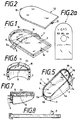
- Figures 1 and 2 thus show in perspective a flat carrying body 3 with a display surface 4 surrounded by an upwardly projecting edge 10, whereby a recess 11 is formed for accommodating information/advertising 1 in the form of a sheet of paper or card of the kind illustrated in figure 2a.
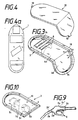
- a transparent cover 12 having securing organs 13 in the form of projecting lugs can be placed in the recess 11 on top of the information/advertising label 1 and is secured by the lugs being brought into engagement with complementary securing organs 14 in the form of openings in said upwardly projecting edge 10.
- the carrying body and thus the sheet containing information/advertising, is elongate, which gives rise to a large display area 4 which extends in the longitudinal direction of the gun head 2a approximately from the rear edge 2b' of the gun barrel 2b at the foremost edge 2a' of the gun head 2a and backwards to the foremost edge 2c' of the handle 2c of the gun head 2a, cf. figure 9.
- This display surface 4 can contain clear information regarding, for example, the quality and brand of the fuel on one part, and an advertisment on the other part.
- the attachment component 5 of the carrying body 3 comprises an attachment band 5a fixed to the underside of the carrying body 3 by means of an eye/groove 6.
- the eye/groove 6 may optionally be grooved on the side which faces down towards the filler gun.
- the attachment band 5a may, of course, optionally be attached to the underside of the carrying body 3 by any kind of means whatsoever such as adhesives or welding.
- the attachment band 5a may consist of a tension adjusting band where one end of said band comprises a leading-in means for securing the other end of the band when it is fed in and tightened.
- the attachment band 5a can also be made of a hose clip secured to the underside of the carrying body 3.
- attachment bands are designed first and foremost to grip the foremost part of the gun head 2a or around the barrel 2b of the filler gun 2. On moderate tightening of the attachment band, the carrying body will be held secure in the correct position on the head 2a of the gun.
- the attachment component 5 can, in a special design not shown in the drawing, consist of a sleeve attached to the underside of the carrying body 3 which is designed to be fed onto the gun barrel 2b thereby holding the carrying body in a fixed position on the gun head.
- the sleeve can be elastic thereby being provided with a clamp effect which reinforces the holding effect.
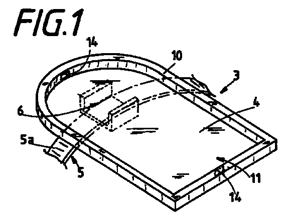
- Said sleeve can be made in a special way as shown in figures 5, 6 and 7 where the carrying body 3 is made with a skirt 7 which projects downwardly from the display surface 4 in order to envelop the sides of the gun head 2a and having an opening 5b, the function of which corresponds to that of the aforementioned sleeve, which constitutes attachment component 5 in the skirt 7.
- the opening 5b is arranged at one end 3a of the carrying body 3 to enable said carrying body to be fed onto the gun barrel 2b and optionally onto the foremost end of the gun head 2a.
- the back 3b of the carrying body 3 is attached to the forward part 3a thereof so as to be upwardly pivotal via a hinge 8 across the display surface 4.
- the skirt 7 is split at this point, the split extending from each end of the hinge 8 and out to the edge 7a of the skirt and releasable securing organs 9 are arranged in the facing splits in the skirt 7. In this way said back 3b can be pivoted downwards in the mounted position on the filler gun and interlock with the back of the gun head 2a.
- the display surface will be divided into two surfaces 4a,4b, each of which can carry appropriate information/advertising.
- This design of the carrying body 3 thus provides a display surface 4 which extends over a substantial part of the length of the gun head 2a.
- FIG 3 A corresponding elongate display surface 4 consisting of two part surfaces 4a,4b square to one another is shown in figure 3 which illustrates a carrying body with a front part equivalent to the carrying body according to figure 1 and having an extension at it rear end, whereby the total display surface 4 comprises a front and a back part 4a,4b square to one another.
- the attachment component 5 can, in an alternative design, consist of a resilient clamp 5c made of steel or any other expedient material, secured to the underside of the carrying body 3 with the clamp arms 5d projecting outwards from the underside.
- the carrying body 3 can hereby quite simply be pushed from above onto the filler gun 2 so that the resilient clamp 5c grips around the gun barrel 2b or gun head 2a.
- the carrying body can be equipped with two resilient clamps 5c which grip around each of two said parts of the filler gun 2.
- the carrying body 3 and the attachment component 5, optionally in the form of said skirt 7 with opening 5b, can be manufactured in an elastic material, eg, in that all parts are dead mould cast in one piece.
- the carrying body 3 can be mounted on the filler gun 2 in that the gun barrel 2b, or the front part of the gun head 2b, is inserted into the attachment component 5 which has an opening 5b.
- the attachment component can be made of said resilient clamp 5c, whereby the carrying body 3 quite simply is pressed into place from the top of the gun head.
- Advertising/information labels can be attached to the display surface 4 of the carrying body 3 in any expedient manner whatsoever such as by using an adhesive. However, to facilitate changing the labels and at the same time achieve protection of the information/advertising label 1, the solution according to figures 1, 3 and 5 is desirable.
- the label can hereby be placed in the recess 11 and covered by means of the transparent cover or cover plate 12.
- the device according to the invention will, on use, provide a petrol/fuel customer with clear and full information with regard to the brand and quality of the fuel. This should prevent a vehicle from being filled with the wrong fuel and thereby save the customer from the problems this would cause and save the petrol station/company from any liability for damages in that the filler gun carries clear information about the fuel quality which the customer could not possibly fail to see. During the actual process of filling his vehicle, the consumer will, at the same time, have ample opportunity to read the advertisement/message that has been affixed to the display surface.
Landscapes
- Engineering & Computer Science (AREA)
- Physics & Mathematics (AREA)
- General Physics & Mathematics (AREA)
- Theoretical Computer Science (AREA)
- Mechanical Engineering (AREA)
- Loading And Unloading Of Fuel Tanks Or Ships (AREA)
- Display Racks (AREA)
- Details Of Rigid Or Semi-Rigid Containers (AREA)
- Vehicle Waterproofing, Decoration, And Sanitation Devices (AREA)
- Filling Or Discharging Of Gas Storage Vessels (AREA)
- Joints That Cut Off Fluids, And Hose Joints (AREA)
- Reciprocating Pumps (AREA)
- Fuel-Injection Apparatus (AREA)
Abstract
Description
- The present invention relates to a device for placing information/advertising on the filler gun of a fuel pump, comprising a carrying body placed on the head of the gun having at least one display surface for said information/advertising as is disclosed in the preamble in independent claim 1 hereinbelow.
- The affixing of information on the head of a filler gun is known from, inter alia, US Patent No. 5.058.637 where a securing means in the form of an elastic stocking is fed onto the filler gun, said stocking being equipped with a display surface for information or advertising, which surface is covered by a transparent cover. The display surface in this known solution is circular and is limited to a small part only of the gun head and the space available for information and/or advertising is limited. The actual method of securing the display surface, which comprises a flexible dead mould cast sleeve, restricts the use of a device of this kind to filler guns which have a special form. This problem can, of course, be solved by manufacturing sleeves of different forms adapted to fit filler guns of different shapes.
- The purpose of the present invention is to provide a device for placing information/advertising on the head of a filler gun and which does not have the disadvantages of a limited display surface referred to hereinabove.
- This is achieved according to the present invention by means of the characteristic features which are disclosed in the characterizing clause of claim 1 hereinbelow and the dependent claims also hereinbelow.
- A larger display surface, with space for both information and advertising, is thus provided in that the display surface of the carrying body extends over a substantial part of the length of the head of the gun.
- As disclosed in the subsequent description of the drawings, the securing component may consist of an attachment band fixed to the underside of the carrying body by means of suitable means such as adhesives, welding or mechanical fixing wherein the attachment band is fixed to the carrying body by means of an eye/groove provided on the underside of said carrying body. The attachment band may also be in the form of a hose clip.
- The attachment band may also consist of two arms which form an integrated part of the carrying body, the ends of said arms being optionally furnished with a barb, and also a through-going screw with nuts being arranged between the carrying body and the gun head, which press said arms against the gun head.
- Other features of the invention which are disclosed in the subsequent dependent claims will be described in more detail in the following description of the invention made with reference to the drawing.
- In the drawing
- figure 1 illustrates a carrying body with a display surface and an attachment band fixed to its underside,
- figure 2 depicts a transparent cover for mounting on top of an information and advertising sticker positioned on the display surface,
- figure 2a depicts said sticker,
- figure 3 illustrates a carrying body with two display surfaces square to one another,
- figure 4 depicts a transparent cover designed for contact with the whole of the display surface,
- figure 4a shows an information and advertising sticker adapted to fit the extra long display surface,
- figure 5 illustrates the carrying body with a downwardly projecting skirt for enveloping the sides of the gun head and with an opening for interaction with the gun barrel,
- figure 6 shows the back of the display surface and the skirt in figure 5 which is pivotally attached to the front and can be secured in an angular position by means of securing organs,
- figure 7 illustrates the front of the carrying body according to figure 5,
- figure 8 shows an attachment band of the tension adjusting kind,
- figure 9 shows a filler gun seen from the side, and
- figure 10 shows a carrying body with two resilient clamps fixed to the underside thereof.
- Figures 1 and 2 thus show in perspective a flat carrying
body 3 with adisplay surface 4 surrounded by an upwardly projectingedge 10, whereby arecess 11 is formed for accommodating information/advertising 1 in the form of a sheet of paper or card of the kind illustrated in figure 2a. Atransparent cover 12 having securingorgans 13 in the form of projecting lugs can be placed in therecess 11 on top of the information/advertising label 1 and is secured by the lugs being brought into engagement withcomplementary securing organs 14 in the form of openings in said upwardly projectingedge 10. It is shown clearly on the drawing that the carrying body, and thus the sheet containing information/advertising, is elongate, which gives rise to alarge display area 4 which extends in the longitudinal direction of thegun head 2a approximately from therear edge 2b' of thegun barrel 2b at theforemost edge 2a' of thegun head 2a and backwards to theforemost edge 2c' of thehandle 2c of thegun head 2a, cf. figure 9. Thisdisplay surface 4 can contain clear information regarding, for example, the quality and brand of the fuel on one part, and an advertisment on the other part. - The
attachment component 5 of thecarrying body 3 comprises anattachment band 5a fixed to the underside of thecarrying body 3 by means of an eye/groove 6. The eye/groove 6 may optionally be grooved on the side which faces down towards the filler gun. Theattachment band 5a may, of course, optionally be attached to the underside of thecarrying body 3 by any kind of means whatsoever such as adhesives or welding. Theattachment band 5a may consist of a tension adjusting band where one end of said band comprises a leading-in means for securing the other end of the band when it is fed in and tightened. Theattachment band 5a can also be made of a hose clip secured to the underside of the carryingbody 3. These various forms of attachment bands are designed first and foremost to grip the foremost part of thegun head 2a or around thebarrel 2b of the filler gun 2. On moderate tightening of the attachment band, the carrying body will be held secure in the correct position on thehead 2a of the gun. - The
attachment component 5 can, in a special design not shown in the drawing, consist of a sleeve attached to the underside of the carryingbody 3 which is designed to be fed onto thegun barrel 2b thereby holding the carrying body in a fixed position on the gun head. The sleeve can be elastic thereby being provided with a clamp effect which reinforces the holding effect. - Said sleeve can be made in a special way as shown in figures 5, 6 and 7 where the carrying
body 3 is made with a skirt 7 which projects downwardly from thedisplay surface 4 in order to envelop the sides of thegun head 2a and having an opening 5b, the function of which corresponds to that of the aforementioned sleeve, which constitutesattachment component 5 in the skirt 7. The opening 5b is arranged at oneend 3a of the carryingbody 3 to enable said carrying body to be fed onto thegun barrel 2b and optionally onto the foremost end of thegun head 2a. - The
back 3b of thecarrying body 3 is attached to theforward part 3a thereof so as to be upwardly pivotal via ahinge 8 across thedisplay surface 4. The skirt 7 is split at this point, the split extending from each end of thehinge 8 and out to theedge 7a of the skirt andreleasable securing organs 9 are arranged in the facing splits in the skirt 7. In this way said back 3b can be pivoted downwards in the mounted position on the filler gun and interlock with the back of thegun head 2a. In this design of thecarrying body 3, the display surface will be divided into twosurfaces carrying body 3 thus provides adisplay surface 4 which extends over a substantial part of the length of thegun head 2a. - A corresponding
elongate display surface 4 consisting of twopart surfaces total display surface 4 comprises a front and aback part - The
attachment component 5 can, in an alternative design, consist of aresilient clamp 5c made of steel or any other expedient material, secured to the underside of thecarrying body 3 with theclamp arms 5d projecting outwards from the underside. The carryingbody 3 can hereby quite simply be pushed from above onto the filler gun 2 so that theresilient clamp 5c grips around thegun barrel 2b orgun head 2a. - Optionally, the carrying body can be equipped with two
resilient clamps 5c which grip around each of two said parts of the filler gun 2. - The
carrying body 3 and theattachment component 5, optionally in the form of said skirt 7 with opening 5b, can be manufactured in an elastic material, eg, in that all parts are dead mould cast in one piece. - Thus the carrying
body 3 can be mounted on the filler gun 2 in that thegun barrel 2b, or the front part of thegun head 2b, is inserted into theattachment component 5 which has an opening 5b. Optionally, the attachment component can be made of saidresilient clamp 5c, whereby thecarrying body 3 quite simply is pressed into place from the top of the gun head. - Advertising/information labels can be attached to the
display surface 4 of thecarrying body 3 in any expedient manner whatsoever such as by using an adhesive. However, to facilitate changing the labels and at the same time achieve protection of the information/advertising label 1, the solution according to figures 1, 3 and 5 is desirable. The label can hereby be placed in therecess 11 and covered by means of the transparent cover orcover plate 12. - The device according to the invention will, on use, provide a petrol/fuel customer with clear and full information with regard to the brand and quality of the fuel. This should prevent a vehicle from being filled with the wrong fuel and thereby save the customer from the problems this would cause and save the petrol station/company from any liability for damages in that the filler gun carries clear information about the fuel quality which the customer could not possibly fail to see. During the actual process of filling his vehicle, the consumer will, at the same time, have ample opportunity to read the advertisement/message that has been affixed to the display surface.
Claims (10)
- A device for placing information/advertising (1) on a filler gun (2) of a fuel pump of the kind having in series a gun barrel (2b), a gun head (2a) and a gun handle (2c), a first junction at which a rear end (2b') of said gun barrel (2b) joins a front end (2a') of said gun head (2a) and a second junction at which a rear end of said gun head (2a) joins a front end (2c') of said gun handle (2c), said device providing:a display surface (4) supported by a carrying body (3) being releasably attachable to said filler gun for displaying one or more said information/advertising readily viewable by a gun user,characterized in that said display surface (4) has a first display surface portion (4a) being substantially parallel to the gun head (2a) and the gun handle (2c) and a second display surface portion (4b) being substantially parallel to the gun barrel (2b) when said carrying body is fitted onto said filler gun, the entire display surface being so configured that it extends longitudinally along and over a top region of said filler gun from approximately said first junction to approximately said second junction when said carrying body is attached to said filler gun.
- The device according to claim 1, characterized in that the width of said display surface (4) is, at least over part of its entire length, greater than the width of said gun head (2a).
- The device according to claim 1 or 2, characterized in that said first and second display surface portions (4a, 4b) are generally planar.
- The device according to any of claims 1 - 3, characterized in that said carrying body (3) includes a downwardly projecting peripheral skirt portion (7) extending from at least that portion of said carrying body so as to envelop the sides of said gun head (2a) when said carrying body is fitted onto said filler gun.
- The device according to any of claims 1 - 4, characterized in that said carrying body (3) is provided with an aperture (5b) in its one end portion to be disposed near said first junction to thereby secure said carrying body to said filler gun when said carrying body is fitted onto said filler gun.
- The device according to claim 5, characterized in that said carrying body (3) defines the other end portion for interlocking with said filler gun near said second junction when said carrying body is fitted onto said filler gun.
- The device according to any of claims 1 - 6, characterized in that it includes a transparent cover (12) adapted for removable attachment to said display surface (4) of said carrying body (3) to thereby facilitate changing of said information/advertising viewable by said user.
- The device according to any of claims 1 - 7, characterized in that said carrying body (3) has a first carrying body portion (3a) and a second carrying body portion (3b) which are pivotally interconnected by a hinge portion (8), and that securing means (9) are provided for adjusting a mutual angle formed by said first and second carrying body portions.
- The device according to claim 1, characterized in that said carrying body (3) is attached to said filler gun by an attachment band (5a).
- The device according to claim 1, characterized in that said carrying body (3) is attached to said filler gun by a resilient clamp (5c).
Applications Claiming Priority (9)
| Application Number | Priority Date | Filing Date | Title |
|---|---|---|---|
| NO920434 | 1992-02-03 | ||
| NO920434A NO920434D0 (en) | 1992-02-03 | 1992-02-03 | COMBINED BRAND AND ADVERTISING PLATE |
| NO921637 | 1992-04-28 | ||
| NO921637A NO921637D0 (en) | 1992-04-28 | 1992-04-28 | COMBINED LABELING AND ADVERTISING PLATE FOR FUEL / DIESEL / GAS REFILLING GASES AT PETROL STATIONS |
| NO921763A NO921763D0 (en) | 1992-05-05 | 1992-05-05 | COMBINED LABELING AND ADVERTISING FIXING DEVICE FOR FUEL / GAS / DIESEL FILLING PISTOLS AT FUEL STATIONS |
| NO921763 | 1992-05-05 | ||
| NO922580A NO175397C (en) | 1992-02-03 | 1992-06-30 | Device for placing information / advertising on a fuel pump refill gun |
| NO922580 | 1992-06-30 | ||
| EP93904407A EP0643863B2 (en) | 1992-02-03 | 1993-02-03 | Means for placing information/advertising on a fuel dispensing nozzle of a petrol dispensing apparatus |
Related Parent Applications (2)
| Application Number | Title | Priority Date | Filing Date |
|---|---|---|---|
| EP93904407A Division EP0643863B2 (en) | 1992-02-03 | 1993-02-03 | Means for placing information/advertising on a fuel dispensing nozzle of a petrol dispensing apparatus |
| EP93904407.9 Division | 1993-08-08 |
Publications (2)
| Publication Number | Publication Date |
|---|---|
| EP0791908A2 true EP0791908A2 (en) | 1997-08-27 |
| EP0791908A3 EP0791908A3 (en) | 1997-11-05 |
Family
ID=27484210
Family Applications (2)
| Application Number | Title | Priority Date | Filing Date |
|---|---|---|---|
| EP97108356A Withdrawn EP0791908A3 (en) | 1992-02-03 | 1993-02-03 | Means for placing information/advertising on a fuel dispensing nozzle of a petrol dispensing apparatus |
| EP93904407A Expired - Lifetime EP0643863B2 (en) | 1992-02-03 | 1993-02-03 | Means for placing information/advertising on a fuel dispensing nozzle of a petrol dispensing apparatus |
Family Applications After (1)
| Application Number | Title | Priority Date | Filing Date |
|---|---|---|---|
| EP93904407A Expired - Lifetime EP0643863B2 (en) | 1992-02-03 | 1993-02-03 | Means for placing information/advertising on a fuel dispensing nozzle of a petrol dispensing apparatus |
Country Status (19)
| Country | Link |
|---|---|
| EP (2) | EP0791908A3 (en) |
| JP (1) | JP2633393B2 (en) |
| KR (1) | KR0152429B1 (en) |
| AT (1) | ATE161350T1 (en) |
| BG (1) | BG62019B1 (en) |
| BR (1) | BR9305830A (en) |
| CA (1) | CA2129365C (en) |
| CZ (1) | CZ280975B6 (en) |
| DE (1) | DE69315835T3 (en) |
| DK (1) | DK0643863T4 (en) |
| ES (1) | ES2110598T5 (en) |
| FI (1) | FI119370B (en) |
| GR (1) | GR3026049T3 (en) |
| HU (1) | HU217311B (en) |
| NO (1) | NO175397C (en) |
| OA (1) | OA09989A (en) |
| SG (1) | SG48948A1 (en) |
| SK (1) | SK279638B6 (en) |
| WO (1) | WO1993015493A1 (en) |
Cited By (1)
| Publication number | Priority date | Publication date | Assignee | Title |
|---|---|---|---|---|
| US10526954B2 (en) | 2015-08-06 | 2020-01-07 | Garrett Transportation I Inc. | Turbocharger assembly |
Families Citing this family (22)
| Publication number | Priority date | Publication date | Assignee | Title |
|---|---|---|---|---|
| US5619815A (en) * | 1995-02-06 | 1997-04-15 | Greene; Dennis | POG holder and method |
| NO961503D0 (en) * | 1995-07-05 | 1996-04-16 | Alvern Norway As | Information / advertising device |
| US6131317A (en) * | 1996-01-25 | 2000-10-17 | Alvern Asa | Display apparatus |
| US5864975A (en) * | 1996-01-25 | 1999-02-02 | Alvern Asa | Display apparatus |
| US5848487A (en) * | 1996-01-25 | 1998-12-15 | Alvern-Norway A/S | Display apparatus for a fluid pump having an upper surface with indentations |
| US6202332B1 (en) | 1996-01-25 | 2001-03-20 | Alvern Asa | Display apparatus having a pivotal message card holder |
| US5806217A (en) * | 1996-01-25 | 1998-09-15 | Alvern-Norway A/S | Display apparatus |
| US5819450A (en) * | 1996-01-25 | 1998-10-13 | Alvern-Norway A/S | Display apparatus for a fluid pump having a double upper frame |
| US5887367A (en) * | 1996-01-25 | 1999-03-30 | Alvern-Norway A/S | Display apparatus for a fluid pump having two pivotal frame members |
| US5864977A (en) * | 1996-05-08 | 1999-02-02 | Alvern-Norway A/S | Display apparatus attachable to a fluid pump filler gun |
| AU2936397A (en) * | 1996-05-08 | 1997-11-26 | Stein Alvern | Display apparatus attachable to a fluid pump filler gun |
| US5822902A (en) * | 1996-07-19 | 1998-10-20 | Alvern Norway A/S | Device for displaying information on a fuel pump filler gun |
| US5810063A (en) * | 1996-08-23 | 1998-09-22 | Alvern-Norway A/S | Display apparatus |
| US6216376B1 (en) | 1996-09-18 | 2001-04-17 | Alvern Asa | Display apparatus |
| US5862617A (en) * | 1996-09-30 | 1999-01-26 | Alvern-Norway A/S | Display apparatus |
| US6061942A (en) * | 1997-03-14 | 2000-05-16 | Alvern-Norway A/S | Fluid filler gun display device having a placard with a three-dimensional image |
| EP2093183A1 (en) | 2008-02-20 | 2009-08-26 | Nozzad (UK) Limited | Hood for fuel nozzle |
| RU2482057C2 (en) * | 2008-09-17 | 2013-05-20 | Франклин Фьюэлинг Системз, Инк. | Fuel filling gun |
| US8752597B2 (en) | 2008-09-17 | 2014-06-17 | Franklin Fueling Systems, Inc. | Fuel dispensing nozzle |
| EP2630043A4 (en) | 2010-10-21 | 2016-04-06 | Opw Fueling Components Inc | Fuel dispensing nozzle |
| KR200471679Y1 (en) * | 2013-10-02 | 2014-03-07 | 주식회사 비아이스트라 | Advertising device for air gun |
| KR102311272B1 (en) * | 2021-01-21 | 2021-10-13 | 김범수 | Protecting Cover For Gas Gun Having Advertising Means |
Citations (1)
| Publication number | Priority date | Publication date | Assignee | Title |
|---|---|---|---|---|
| US5058637A (en) | 1989-08-23 | 1991-10-22 | M&M Displays, Inc. | Message display saddle for fuel dispensing nozzle |
Family Cites Families (7)
| Publication number | Priority date | Publication date | Assignee | Title |
|---|---|---|---|---|
| CH543449A (en) * | 1972-05-02 | 1973-10-31 | Oxy Metal Finishing Corp | Apparatus for dispensing liquid |
| GB1473828A (en) * | 1973-05-03 | 1977-05-18 | Dresser Europe Sa | Seven-segment display arrangement and liquid fuel dispensing pump embodying the same |
| SE390722B (en) * | 1974-03-08 | 1977-01-17 | Ljungmans Verkstader Ab | DEVICE FOR FUEL-MINUTING SYSTEMS FOR THE TRANSFER OF INFORMATION BETWEEN AN ELECTRONIC INDICATOR UNIT AND BODIES FOR DELIVERING AND RECEIVING INFORMATION AND SUPPLY OF DRIVE CURRENT TO THE ... |
| GB2147273A (en) * | 1983-10-01 | 1985-05-09 | Donald Green | Apparatus for dispensing fluids |
| DE3438939C1 (en) * | 1984-10-24 | 1986-05-22 | Deutsche Gerätebau GmbH, 4796 Salzkotten | Device for transmitting and displaying control and measurement data relating to flammable liquids or gases conveyed in pipelines or flexible hose lines |
| FR2649524A1 (en) * | 1989-07-04 | 1991-01-11 | Vassal Michel | MESSAGE HOLDER FOR FUEL DISPENSING GUN |
| US5184655A (en) * | 1989-08-23 | 1993-02-09 | M & M Displays, Inc. | Message display boot for fuel dispensing nozzle |
-
1992
- 1992-06-30 NO NO922580A patent/NO175397C/en not_active IP Right Cessation
-
1993
- 1993-02-03 AT AT93904407T patent/ATE161350T1/en active
- 1993-02-03 SK SK926-94A patent/SK279638B6/en not_active IP Right Cessation
- 1993-02-03 DK DK93904407T patent/DK0643863T4/en active
- 1993-02-03 WO PCT/NO1993/000021 patent/WO1993015493A1/en not_active Ceased
- 1993-02-03 SG SG1996003955A patent/SG48948A1/en unknown
- 1993-02-03 EP EP97108356A patent/EP0791908A3/en not_active Withdrawn
- 1993-02-03 KR KR1019940702664A patent/KR0152429B1/en not_active Expired - Fee Related
- 1993-02-03 JP JP5513118A patent/JP2633393B2/en not_active Expired - Lifetime
- 1993-02-03 HU HU9402260A patent/HU217311B/en unknown
- 1993-02-03 EP EP93904407A patent/EP0643863B2/en not_active Expired - Lifetime
- 1993-02-03 CZ CZ941873A patent/CZ280975B6/en not_active IP Right Cessation
- 1993-02-03 CA CA002129365A patent/CA2129365C/en not_active Expired - Fee Related
- 1993-02-03 BR BR9305830A patent/BR9305830A/en not_active Application Discontinuation
- 1993-02-03 DE DE69315835T patent/DE69315835T3/en not_active Expired - Lifetime
- 1993-02-03 ES ES93904407T patent/ES2110598T5/en not_active Expired - Lifetime
-
1994
- 1994-08-02 OA OA60546A patent/OA09989A/en unknown
- 1994-08-02 BG BG98946A patent/BG62019B1/en unknown
- 1994-08-03 FI FI943615A patent/FI119370B/en not_active IP Right Cessation
-
1998
- 1998-02-04 GR GR980400217T patent/GR3026049T3/en unknown
Patent Citations (1)
| Publication number | Priority date | Publication date | Assignee | Title |
|---|---|---|---|---|
| US5058637A (en) | 1989-08-23 | 1991-10-22 | M&M Displays, Inc. | Message display saddle for fuel dispensing nozzle |
Non-Patent Citations (6)
| Title |
|---|
| Affidativ by Mr Howard John Farthing |
| Affidativ by Mr Keith William Rawlings |
| Bundle of invoices dated 1988 to 1991 for sales of the nozzle collars including identification by code NZCD and NZCU |
| Copy of a Texaco poster identifying the nozzle collar under code NZCU/NZCD |
| Copy of invoice from Janet Ford Design dated 15th July 1988 in relation to preparation of poster D4 |
| Photographs showing the nozzle collar and badge in use. D3A/D3B/D3C |
Cited By (1)
| Publication number | Priority date | Publication date | Assignee | Title |
|---|---|---|---|---|
| US10526954B2 (en) | 2015-08-06 | 2020-01-07 | Garrett Transportation I Inc. | Turbocharger assembly |
Also Published As
Similar Documents
| Publication | Publication Date | Title |
|---|---|---|
| EP0791908A2 (en) | Means for placing information/advertising on a fuel dispensing nozzle of a petrol dispensing apparatus | |
| US6289616B1 (en) | Means for placing information/advertising on a fuel dispensing nozzle of a petrol dispensing apparatus | |
| JP3307935B2 (en) | Bundling device for bundling multiple containers, especially bundling device for bundling multiple beverage containers | |
| FR2799148A3 (en) | Stapler for documents has spring-loaded staple container and pressure cover, to prevent ends of staples being bent outwards | |
| AU668711C (en) | Means for placing information/advertising on a fuel dispensing nozzle of a petrol dispensing apparatus | |
| NZ249243A (en) | Information/advertising applicator placed over the head of the filler gun of a fuel pump | |
| US10311761B2 (en) | Storage label device | |
| CA2226113C (en) | Information carrying device for a fuel dispensing nozzle | |
| US20020071919A1 (en) | Reusable gift bows and method of using same | |
| WO2013127637A1 (en) | A floral arrangement cardette incorporating advertisement | |
| WO1997042616A1 (en) | Display apparatus attachable to a fluid pump filler gun |
Legal Events
| Date | Code | Title | Description |
|---|---|---|---|
| PUAI | Public reference made under article 153(3) epc to a published international application that has entered the european phase |
Free format text: ORIGINAL CODE: 0009012 |
|
| AC | Divisional application: reference to earlier application |
Ref document number: 643863 Country of ref document: EP |
|
| AK | Designated contracting states |
Kind code of ref document: A2 Designated state(s): AT BE CH DE DK ES FR GB GR IE IT LI LU MC NL PT SE |
|
| PUAL | Search report despatched |
Free format text: ORIGINAL CODE: 0009013 |
|
| RHK1 | Main classification (correction) |
Ipc: B67D 5/37 |
|
| AK | Designated contracting states |
Kind code of ref document: A3 Designated state(s): AT BE CH DE DK ES FR GB GR IE IT LI LU MC NL PT SE |
|
| 17P | Request for examination filed |
Effective date: 19971128 |
|
| RAP1 | Party data changed (applicant data changed or rights of an application transferred) |
Owner name: ALVERN ASA |
|
| 17Q | First examination report despatched |
Effective date: 19980427 |
|
| TPAD | Observations filed by third parties |
Free format text: ORIGINAL CODE: EPIDOS TIPA |
|
| STAA | Information on the status of an ep patent application or granted ep patent |
Free format text: STATUS: THE APPLICATION IS DEEMED TO BE WITHDRAWN |
|
| 18D | Application deemed to be withdrawn |
Effective date: 19990710 |