EP0791802B1 - Scanning type near field interatomic force microscope - Google Patents
Scanning type near field interatomic force microscope Download PDFInfo
- Publication number
- EP0791802B1 EP0791802B1 EP96120094A EP96120094A EP0791802B1 EP 0791802 B1 EP0791802 B1 EP 0791802B1 EP 96120094 A EP96120094 A EP 96120094A EP 96120094 A EP96120094 A EP 96120094A EP 0791802 B1 EP0791802 B1 EP 0791802B1
- Authority
- EP
- European Patent Office
- Prior art keywords
- probe
- sample
- near field
- force microscope
- interatomic force
- Prior art date
- Legal status (The legal status is an assumption and is not a legal conclusion. Google has not performed a legal analysis and makes no representation as to the accuracy of the status listed.)
- Expired - Lifetime
Links
- 239000000523 sample Substances 0.000 claims description 164
- 239000010453 quartz Substances 0.000 claims description 62
- VYPSYNLAJGMNEJ-UHFFFAOYSA-N silicon dioxide Inorganic materials O=[Si]=O VYPSYNLAJGMNEJ-UHFFFAOYSA-N 0.000 claims description 62
- 239000007788 liquid Substances 0.000 claims description 49
- 230000003287 optical effect Effects 0.000 claims description 36
- 239000000126 substance Substances 0.000 claims description 24
- 238000001514 detection method Methods 0.000 claims description 23
- 239000000463 material Substances 0.000 claims description 7
- 238000005259 measurement Methods 0.000 description 53
- 238000005452 bending Methods 0.000 description 11
- 239000013307 optical fiber Substances 0.000 description 5
- XLOMVQKBTHCTTD-UHFFFAOYSA-N Zinc monoxide Chemical compound [Zn]=O XLOMVQKBTHCTTD-UHFFFAOYSA-N 0.000 description 4
- 238000013459 approach Methods 0.000 description 4
- 238000000034 method Methods 0.000 description 3
- 230000010355 oscillation Effects 0.000 description 3
- 230000003247 decreasing effect Effects 0.000 description 2
- 230000007547 defect Effects 0.000 description 2
- 239000011787 zinc oxide Substances 0.000 description 2
- RTAQQCXQSZGOHL-UHFFFAOYSA-N Titanium Chemical compound [Ti] RTAQQCXQSZGOHL-UHFFFAOYSA-N 0.000 description 1
- 238000004891 communication Methods 0.000 description 1
- 238000006073 displacement reaction Methods 0.000 description 1
- 230000000694 effects Effects 0.000 description 1
- 230000005684 electric field Effects 0.000 description 1
- 230000008020 evaporation Effects 0.000 description 1
- 238000001704 evaporation Methods 0.000 description 1
- 230000001747 exhibiting effect Effects 0.000 description 1
- 238000005286 illumination Methods 0.000 description 1
- 238000004519 manufacturing process Methods 0.000 description 1
- 244000005700 microbiome Species 0.000 description 1
- 238000000399 optical microscopy Methods 0.000 description 1
- 238000012545 processing Methods 0.000 description 1
- 238000007789 sealing Methods 0.000 description 1
- XLYOFNOQVPJJNP-UHFFFAOYSA-N water Substances O XLYOFNOQVPJJNP-UHFFFAOYSA-N 0.000 description 1
- 229910052845 zircon Inorganic materials 0.000 description 1
- GFQYVLUOOAAOGM-UHFFFAOYSA-N zirconium(iv) silicate Chemical compound [Zr+4].[O-][Si]([O-])([O-])[O-] GFQYVLUOOAAOGM-UHFFFAOYSA-N 0.000 description 1
Images


Classifications
-
- G—PHYSICS
- G01—MEASURING; TESTING
- G01Q—SCANNING-PROBE TECHNIQUES OR APPARATUS; APPLICATIONS OF SCANNING-PROBE TECHNIQUES, e.g. SCANNING PROBE MICROSCOPY [SPM]
- G01Q20/00—Monitoring the movement or position of the probe
- G01Q20/04—Self-detecting probes, i.e. wherein the probe itself generates a signal representative of its position, e.g. piezoelectric gauge
-
- B—PERFORMING OPERATIONS; TRANSPORTING
- B82—NANOTECHNOLOGY
- B82Y—SPECIFIC USES OR APPLICATIONS OF NANOSTRUCTURES; MEASUREMENT OR ANALYSIS OF NANOSTRUCTURES; MANUFACTURE OR TREATMENT OF NANOSTRUCTURES
- B82Y20/00—Nanooptics, e.g. quantum optics or photonic crystals
-
- B—PERFORMING OPERATIONS; TRANSPORTING
- B82—NANOTECHNOLOGY
- B82Y—SPECIFIC USES OR APPLICATIONS OF NANOSTRUCTURES; MEASUREMENT OR ANALYSIS OF NANOSTRUCTURES; MANUFACTURE OR TREATMENT OF NANOSTRUCTURES
- B82Y35/00—Methods or apparatus for measurement or analysis of nanostructures
-
- G—PHYSICS
- G01—MEASURING; TESTING
- G01Q—SCANNING-PROBE TECHNIQUES OR APPARATUS; APPLICATIONS OF SCANNING-PROBE TECHNIQUES, e.g. SCANNING PROBE MICROSCOPY [SPM]
- G01Q10/00—Scanning or positioning arrangements, i.e. arrangements for actively controlling the movement or position of the probe
- G01Q10/04—Fine scanning or positioning
- G01Q10/045—Self-actuating probes, i.e. wherein the actuating means for driving are part of the probe itself, e.g. piezoelectric means on a cantilever probe
-
- G—PHYSICS
- G01—MEASURING; TESTING
- G01Q—SCANNING-PROBE TECHNIQUES OR APPARATUS; APPLICATIONS OF SCANNING-PROBE TECHNIQUES, e.g. SCANNING PROBE MICROSCOPY [SPM]
- G01Q30/00—Auxiliary means serving to assist or improve the scanning probe techniques or apparatus, e.g. display or data processing devices
- G01Q30/08—Means for establishing or regulating a desired environmental condition within a sample chamber
- G01Q30/12—Fluid environment
- G01Q30/14—Liquid environment
-
- G—PHYSICS
- G01—MEASURING; TESTING
- G01Q—SCANNING-PROBE TECHNIQUES OR APPARATUS; APPLICATIONS OF SCANNING-PROBE TECHNIQUES, e.g. SCANNING PROBE MICROSCOPY [SPM]
- G01Q60/00—Particular types of SPM [Scanning Probe Microscopy] or microscopes; Essential components thereof
- G01Q60/02—Multiple-type SPM, i.e. involving more than one SPM techniques
- G01Q60/06—SNOM [Scanning Near-field Optical Microscopy] combined with AFM [Atomic Force Microscopy]
-
- G—PHYSICS
- G01—MEASURING; TESTING
- G01Q—SCANNING-PROBE TECHNIQUES OR APPARATUS; APPLICATIONS OF SCANNING-PROBE TECHNIQUES, e.g. SCANNING PROBE MICROSCOPY [SPM]
- G01Q60/00—Particular types of SPM [Scanning Probe Microscopy] or microscopes; Essential components thereof
- G01Q60/18—SNOM [Scanning Near-Field Optical Microscopy] or apparatus therefor, e.g. SNOM probes
- G01Q60/22—Probes, their manufacture, or their related instrumentation, e.g. holders
-
- Y—GENERAL TAGGING OF NEW TECHNOLOGICAL DEVELOPMENTS; GENERAL TAGGING OF CROSS-SECTIONAL TECHNOLOGIES SPANNING OVER SEVERAL SECTIONS OF THE IPC; TECHNICAL SUBJECTS COVERED BY FORMER USPC CROSS-REFERENCE ART COLLECTIONS [XRACs] AND DIGESTS
- Y10—TECHNICAL SUBJECTS COVERED BY FORMER USPC
- Y10S—TECHNICAL SUBJECTS COVERED BY FORMER USPC CROSS-REFERENCE ART COLLECTIONS [XRACs] AND DIGESTS
- Y10S977/00—Nanotechnology
- Y10S977/84—Manufacture, treatment, or detection of nanostructure
- Y10S977/849—Manufacture, treatment, or detection of nanostructure with scanning probe
- Y10S977/86—Scanning probe structure
- Y10S977/862—Near-field probe
Definitions
- the present invention relates to a scanning type near field interatomic force microscope which observes the surface shape of a substance to be measured by using interatomic force acting between substances and at the same time, observes optical characteristics of the substance to be measured in a minute region by a probe made of a light transmitting material.
- a shaft portion of a hook-shaped probe 1 of a light transmitting material is used as a cantilever.
- the light emitted from an optical source 8 passes through the probe 1 formed of an optical fiber and is made to irradiate a sample 2 from the tip thereof.
- the transmitting light influenced by the optical characteristics of the sample 2 is detected by an optical detector 11 through an objective lens 9 and a reflecting mirror 10.
- the relative movement between the probe 1 and the sample 2 is performed by an XYZ scanner 12.
- the probe 1 is attached to a bimorph 4 for oscillating the tip of the probe 1 in the vertical direction.
- the reason is to prevent the tip of the probe 1 and the surface of the sample 2 from being seriously damaged by the roughness of the surface of the sample 2 when the probe 1 is made to scan the surface of the sample 2 in the horizontal direction.
- the bending of the cantilever caused by the interatomic force acting between the tip of the probe 1 and the surface of the sample 2 is detected by a displacement magnifying mechanism by means of an optical lever system 14 by using an optical reflector provided on a portion of the cantilever of the probe 1.
- the detecting light affects the near field optical measurement.
- the optical axis of the detecting light for detecting the bending of the cantilever must be aligned with the optical reflector of the cantilever, or the alignment of optical detecting elements must be conducted, that is, the troublesome adjustment operations must be made in order to carry out the measurement.
- Another object of the invention is to provide a scanning type near field interatomic force microscope having a freedom with respect to the arrangement of an optical system for near field optical measurement.
- a further object of the invention is to provide a scanning type near field interatomic force microscope which has a miniaturized measurement system so that the measurement in a specific enviroment such as in a liquid, vacuum, or a low temperature container becomes easy.
- the present invention is configured such that in a scanning type near field interatomic force microscope, a shaft portion of a hook-shaped probe is attached to a side surface of a quartz oscillator.
- the direction of attaching the probe is such that when the quartz oscillator oscillates, the vibration direction of the tip of the probe becomes the direction in which the tip of the probe is directed.
- the attachment position is configured such that the intrinsic frequency of the tip portion of the probe protruding from the quartz oscillator does not become lower than the oscillation frequency of the quartz probe.
- the quartz oscillator to which the probe is attached is made to oscillate at a resonance frequency when the tip of the probe is sufficiently remote from the surface of the sample.
- the interatomic force acts between the tip of the probe and the surface of the sample, and the resonance frequency of the quartz oscillator is changed by this force.
- This change of the resonance characteristics is detected by measuring a current or voltage between electrodes provided on the quartz oscillator.
- the quartz oscillator As another method of oscillating the quartz oscillator, it is also possible to oscillate the quartz oscillator from the outside by using a bimorph element. In this case, if the electromotive force (electric charge) generated in the electrodes of the quartz oscillator is measured, the resonance characteristics of the quartz oscillator can be measured.
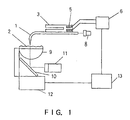
- Fig. 1 shows a first embodiment of a scanning type near field interatomic force microscope of the present invention.
- a probe 1 is attached to the side surface of a quartz oscillator 3.
- the quartz oscillator 3 is of a tuning fork type quartz oscillator used in a quartz clock, and has a resonance frequency of 32.768 kHz in a state where the probe is not attached.
- the probe 1 is a hook-shaped probe for a scanning type near field interatomic force microscope, which has a sharpened tip portion with a minute transmitting hole for transmitting light.
- the probe 1 is formed by processing an optical fiber.
- the probe 1 is attached to the quartz oscillator 3 so that the direction of the tip of the probe 1 is the same as that of oscillation of the quartz oscillator 3.
- a pair of electrodes 5 provided on the quartz oscillator 3 are connected to a drive/detection circuit 6 for the quartz oscillator 3.
- the drive/detection circuit 6 oscillates the quartz oscillator 3 by applying an AC electric field between the electrodes 5 and measures the resonance characteristics of the quartz oscillator 3 by detecting a current flowing between the electrodes 5.
- the light for measuring the characteristics of a sample 2 in a near field is emitted from an optical source 8, passes through the probe 1 formed of the optical fiber, and is made to irradiate from the tip of the probe.
- the sample 2 is a transparent substance, as shown in Fig. 1
- the light influenced by the optical characteristics of the sample 2, as transmitting light is detected by an optical detector 11 through an objective lens 9 and a reflecting mirror 10.
- the relative movement between the probe 1 and the sample 2, such as scanning of the probe 1 on the surface of the sample 2 is carried out by an XYZ scanner 12.
- the XYZ scanner 12 and the drive/detection circuit 6 are controlled by a controller 13.
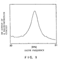
- Fig. 9 shows the resonance characteristics of the probe 1 measured when the quartz oscillator 3 is driven by a voltage of 1V.
- the horizontal axis of abscissa indicates a drive frequency for the quartz oscillator, and the axis of ordinate indicates an output of the drive/detection circuit 6.
- the Q-value of the probe 1 obtained from this measurement example was 184.
- Fig. 2 shows a second embodiment of a scanning type near field interatomic force microscope of the present invention.
- a probe 1 is attached to the side surface of a quartz oscillator 3.
- the quartz oscillator 3 is attached to a bimorph 4, and the bimorph 4 oscillates the quartz oscillator 3 to which the probe 1 is attached.
- a pair of electrodes 5 provided on the quartz oscillator 3 are connected to a detection circuit 7.
- the detection circuit 7 detects electric charges which are generated between the electrodes 5 by the oscillation of the quartz oscillator 3 caused by the bimorph 4, so that the detection circuit measures the resonance characteristics of the quartz oscillator 3.
- Fig. 10 shows the resonance characteristics of the probe 1 which was measured when the bimorph 4 is driven by a voltage of 1V.
- the axis of abscissa indicates a drive frequency for the bimorph 4, and the axis of ordinate indicates an output voltage from the detection circuit 7.
- the Q-value of the probe 1 obtained by this measurement example is 360.
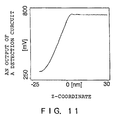
- Fig. 11 shows the measurement result of the change of output values of the detection circuit 7 when the probe 1 is made to approach the surface of the sample 2 under the state where the probe 1 is oscillated at the resonance point.
- the sensibility of the probe 1 in a Z-direction is known from this measurement.
- the sensibility of the probe 1 in the Z-direction was 25 mV/nm.
- the sensibility in the Z-direction is normally about 10 mV/nm, which indicates that the invention has the sensibility superior to the optical lever.
- the probe of the present invention by immersing only the tip of the probe and the surface of the sample into a liquid while preventing liquid from sticking to the electrodes of the quartz oscillator and wiring portions, measurement in the liquid environment can be made.
- the affinity between the surface of the sample and the liquid is low, when a small amount of liquid is put on the surface of the sample, it becomes a state that it is kept in the shape of a drop of liquid.
- the measurement in the liquid environment can me made by establishing the state in which only the tip of the probe is immersed in the liquid.
- the measurement in the liquid environment can be carried out by making a fence on the circumference of the surface of the sample, filling a liquid in the fence, providing a gap in a part of the fence, and inserting the tip of the probe into the fence through the gap. Since the probe is sufficiently thin, it is possible to make the gap thin so that the liquid does not leak from the gap by the surface tension.
- measurement in a liquid can be made by providing a half sealing cover so that an air layer is formed at the portion of the quartz oscillator even if the entire probe is immersed in the liquid.
- Fig. 12 shows an example of resonance characteristics which was measured in the state where the tip of the probe 1 is immersed in a liquid according to the second embodiment of the scanning type near field interatomic force microscope of the present invention.
- the Q-value at this time was 260. Although it was slightly reduced as compared with the Q-value obtained in the measurement in the air as shown in Fig. 10, the shape of the surface of the sample could be really measured. Measuring the sample in the liquid in this way is an indispensable element for measuring the surface shape and optical characteristics of a living substance such as a microorganism or a cell, or a high molecular material while it is in the active state.
- Fig. 4 shows an example according to a measurement in a liquid.
- a lyophobic ring sheet 16 is put on a sample stand, and in the state where a liquid 15 is kept in the shape of a drop of liquid on the surface of the sample 2, the tip of the probe 1 attached to the quartz oscillator 3 is immersed in the liquid to carry out measurement.
- the drop of liquid is sufficiently stable during the measurement.
- the sample 2 is put in a container 17 capable of keeping the liquid 15, it is also possible to carry out the measurement in the liquid.
- the depth of the liquid layer on the surface of the sample is determined by the depth of the container 17 and the thickness of the sample 2.
- the depth of the liquid can be adjusted so that even if the probe 1 is made to approach the surface of the sample 2 at the measurement, the quartz oscillator 3 is not brought into contact with the liquid 15. According to this, the measurement in the liquid can be carried out even in the case where the liquid has an affinity to the surface of the sample so that the drop of liquid is not formed. Also, since a larger amount of liquid than the drop of liquid can be used, even if a volatile liquid is used, stable measurement can be made for a longer time.
- a cover 18 covering a top and a side surface of the probe 1 is provided and the probe system is made to cover the sample 2 put in the liquid 15 so that although the tip of the probe 1 is immersed in the liquid 15, the quartz oscillator 3 is placed in an air layer 21 in the cover 18, the measurement in the liquid can be carried out.
- the cover 18 may be provided with a transparent window 19 so that the sample 2 can be observed from the above, reflective measurement light can be taken out, or outside illumination can be introduced.
- the circumference of the sample 2 is sealed by an oil seal 20, it is possible to prevent the liquid from decreasing due to evaporation thereof so that the measurement for a long time can be carried out in a stable manner.
- the measurement in the liquid can be made also in a share force type scanning type near field interatomic force microscope in which a linear probe 22 is used as shown in Fig. 7, and the tip of the linear probe is made to oscillate in the horizontal direction with respect co the surface of the sample 2 to detect the interatomic force.
- the quartz oscillator a ready-made article used as a clock frequency generator of a watch can be used.
- the quartz oscillator is widely used for the use of a watch or a communication equipment, the manufacturing method thereof is established, and the element can be obtained at a low cost. If such a ready-made article is used for the probe of the scanning type near field interatomic force microscope, the probe can be produced at a low cost. Further, it is also possible to newly produce the quartz oscillator designed for the exclusive use of the scanning type near field interatomic force microscope in accordance with the characteristics such as a spring constant of the cantilever, a resonance frequency, and a Q-value.
- the spring constant as the cantilever of the probe with the quartz oscillator used in the above-mentioned embodiments is 2, 500 N/m.
- this probe can be used to measure a hard sample such as an inorganic substance without any problems, as for a soft sample such as a living substance or a high molecule, if the spring constant is made smaller, the danger of damaging the tip of the probe can be lessened at the measurement. Since the spring constant is determined by the shape of the quartz oscillator, the quartz oscillator having a smaller spring constant maybe designed by making the thickness thin and the length long.
- the resonance frequency of the quartz oscillator used in the above-mentioned embodiments is about 32.7 kHz
- the resonance frequency can be designed as a different value by changing the outer shape of the quartz oscillator and the arrangement of the electrodes. If the quartz oscillator having a higher resonance frequency (for example, 400 kHz) is formed, the measuring speed can be increased so that the measuring time can be shortened.
- the tuning fork type quartz oscillator has originally a Q-value of about 10,000 for resonance in air in the state where the probe is not attached, the Q-value in the above described embodiments is decreased to about 300 since the probe is attached to one side of the quartz oscillator.
- the probe having a higher Q-value can be formed so that the detection sensibility can be increased.
- This method can be similarly applied also to the share force type scanning type near field interatomic force microscope.
- the present invention has been described on the basis of various embodiments, it is needless to say that the present invention is not limited to these embodiments.
- the shape may be rod-shape, plate-shape, or cylinder-shape other than the tuning fork type. In principle, the shape thereof does not matter if it can oscillate the probe.
- the material of the oscillator is not limited to the quartz. Any material exhibiting the piezoelectricity such as ZnO (zinc oxide), PZT (zircon/titanate) or a piezoelectric high molecular material may be applied similarly to the above-mentioned embodiments.
- a probe is attached to a piezoelectric substance, and interatomic force acting between the tip end of the probe and the surface of a sample is detected through a signal from electrodes provided on the piezoelectric substance, so that an optical system conventionally used for measurement of bending of a cantilever becomes unnecessary, whereby there are removed the restriction to a wavelength region for near field optical measurement, and the influence that an optical signal for bending measurement appears as noise in a signal of the near field optical measurement. Also, a troublesome operation such as alignment of an optical axis of detecting light for bending detection becomes unnecessary so that the measurement becomes easy.
- the entire of a measurement system including the probe can be miniaturized, the measurement in a specific environment such as in a liquid, vacuum, or a low temperature container becomes easier than a conventional system.
Landscapes
- Physics & Mathematics (AREA)
- Health & Medical Sciences (AREA)
- General Health & Medical Sciences (AREA)
- General Physics & Mathematics (AREA)
- Nuclear Medicine, Radiotherapy & Molecular Imaging (AREA)
- Radiology & Medical Imaging (AREA)
- Chemical & Material Sciences (AREA)
- Engineering & Computer Science (AREA)
- Nanotechnology (AREA)
- Crystallography & Structural Chemistry (AREA)
- Analytical Chemistry (AREA)
- Life Sciences & Earth Sciences (AREA)
- Biophysics (AREA)
- Optics & Photonics (AREA)
- Length Measuring Devices With Unspecified Measuring Means (AREA)
- Length Measuring Devices By Optical Means (AREA)
Description
- The present invention relates to a scanning type near field interatomic force microscope which observes the surface shape of a substance to be measured by using interatomic force acting between substances and at the same time, observes optical characteristics of the substance to be measured in a minute region by a probe made of a light transmitting material.
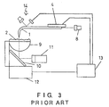
- In a conventional scanning type near field interatomic force microscope, as shown in Fig. 3, a shaft portion of a hook-
shaped probe 1 of a light transmitting material is used as a cantilever. The light emitted from anoptical source 8 passes through theprobe 1 formed of an optical fiber and is made to irradiate asample 2 from the tip thereof. The transmitting light influenced by the optical characteristics of thesample 2 is detected by anoptical detector 11 through anobjective lens 9 and a reflectingmirror 10. The relative movement between theprobe 1 and thesample 2 is performed by anXYZ scanner 12. - The
probe 1 is attached to a bimorph 4 for oscillating the tip of theprobe 1 in the vertical direction. The reason is to prevent the tip of theprobe 1 and the surface of thesample 2 from being seriously damaged by the roughness of the surface of thesample 2 when theprobe 1 is made to scan the surface of thesample 2 in the horizontal direction. - The bending of the cantilever caused by the interatomic force acting between the tip of the
probe 1 and the surface of thesample 2 is detected by a displacement magnifying mechanism by means of anoptical lever system 14 by using an optical reflector provided on a portion of the cantilever of theprobe 1. - These XYZ
scanner 12, bimorph 4, andoptical lever system 14 are controlled by acontroller 13. Such a scanning type near field interatomic force microscope is disclosed in Japanese Laid-Open Patent Publication No. Hei. 7-174542, and Applied Physics Letters vol. 66, no. 24, 1995 pp. 3245 - 3247, H. Muramatsu et. al. : "Near field optical microscopy in liquids" and vol. 66, no. 14, 1995, K. Karrai et. al.: "Piezoelectric tip-sample distance control for near field optical microscopes". - On the other hand, there is a system in which such a cantilever is assembled in a quartz oscillator and the interatomic force is detected by the shift of a resonance frequency of the quartz oscillator, and such an interatomic force microscope is, for example, disclosed in Japanese Laid-Open Patent Publication No. Sho. 63-309803 and No. Hei. 4-102008.
- Further, in the field of a near field microscope, there is known a system in which a linear optical fiber having a sharpened tip is used as a probe, and measurement is conducted in the state where the tip of the probe attached to a quartz oscillator is vibrated in parallel with the surface of the sample.
- In the conventional scanning type near field interatomic force microscope using light to detect the bending of the cantilever, it must be avoided that the detecting light affects the near field optical measurement. For that purpose, it is necessary to make the wavelength region of the detecting light for detecting the bending of the cantilever differ from the wavelength region of the measuring light used in the near field optical measurement. This is a limitation to the near field optical measurement and mounting of a microscope device.
- Further, in the near field optical measurement to detect faint light passing through a minute opening, it is sometimes difficult to avoid the influence of the detecting light for detecting the bending of the probe.
- In addition, there is a problem that the optical system for detecting the bending of the cantilever occupies a part of the space around the probe, so that the arrangement of an optical system for near field optical measurement in a reflecting mode is limited.
- Further, in the conventional device, the optical axis of the detecting light for detecting the bending of the cantilever must be aligned with the optical reflector of the cantilever, or the alignment of optical detecting elements must be conducted, that is, the troublesome adjustment operations must be made in order to carry out the measurement.
- On the other hand, in the system in which the linear optical fiber probe having a sharpened tip is attached to the quartz oscillator and measurement is carried out in the state that the tip of the probe is made to vibrate in parallel with the surface of the sample, there is a defect that when a sample having large roughness is measured, the tip of the probe is apt to be damaged. Further, there is a defect that the space upper the surface of the sample is occupied by the quartz oscillator for oscillating the probe, so that the conventional system is disadvantageous in reflective measurement and observation for positioning of the sample.
- It is an object of the invention to provide a scanning type near field interatomic force microscope without an optical system used for measurement of bending of a cantilever.
- Another object of the invention is to provide a scanning type near field interatomic force microscope having a freedom with respect to the arrangement of an optical system for near field optical measurement.
- A further object of the invention is to provide a scanning type near field interatomic force microscope which has a miniaturized measurement system so that the measurement in a specific enviroment such as in a liquid, vacuum, or a low temperature container becomes easy.
-
- Fig. 1 is a schematic view showing a first embodiment of a scanning type near field interatomic force microscope of the present invention;
- Fig. 2 is a schematic view showing a second embodiment of a scanning type near field interatomic force microscope of the present invention;
- Fig. 3 is a schematic view showing a conventional scanning type near field interatomic force microscope;
- Fig. 4 is a schematic view showing an embodiment of measurement in a liquid by the scanning type near field interatomic force microscope of the present invention;
- Fig. 5 is a schematic view showing another embodiment of measurement in a liquid by the scanning type near field interatomic force microscope of the present invention;
- Fig. 6 is a schematic view showing another embodiment of measurement in a liquid by the scanning type near field interatomic force microscope of the present invention;
- Fig. 7 is a schematic view showing another embodiment of measurement in a liquid by the scanning type near field interatomic force microscope of the present invention;
- Fig. 8 is a view showing an embodiment of a probe system of the scanning type near field interatomic force microscope of the present invention;
- Fig. 9 is a view showing a measurement example of resonance characteristics of a probe of the first embodiment of the scanning type near field interatomic force microscope of the present invention in air;
- Fig. 10 is a view showing a measurement example of resonance characteristics of a probe of the second embodiment of the scanning type near field interatomic force microscope of the present invention in air;
- Fig. 11 is a view showing an approach curve of the probe of the second embodiment of the scanning type near field interatomic force microscope of the present invention; and
- Fig. 12 is a view showing a measurement example of resonance characteristics of the probe of the second embodiment of the scanning type near field interatomic force microscope of the present invention in water.
-
- In order to solve the above-mentioned problems, the present invention is configured such that in a scanning type near field interatomic force microscope, a shaft portion of a hook-shaped probe is attached to a side surface of a quartz oscillator. The direction of attaching the probe is such that when the quartz oscillator oscillates, the vibration direction of the tip of the probe becomes the direction in which the tip of the probe is directed. Further, the attachment position is configured such that the intrinsic frequency of the tip portion of the probe protruding from the quartz oscillator does not become lower than the oscillation frequency of the quartz probe.
- The quartz oscillator to which the probe is attached, is made to oscillate at a resonance frequency when the tip of the probe is sufficiently remote from the surface of the sample. When the probe is made to approach the surface of the sample under the state where the tip of the probe oscillates in the vertical direction with respect to the surface of the sample, the interatomic force acts between the tip of the probe and the surface of the sample, and the resonance frequency of the quartz oscillator is changed by this force. This change of the resonance characteristics is detected by measuring a current or voltage between electrodes provided on the quartz oscillator.
- In order to oscillate the quartz oscillator, there is a method of oscillating the quartz oscillator itself by applying an AC voltage between electrodes of the quartz oscillator. In this case, by measuring the current flowing between the electrodes of the quartz oscillator, the resonance characteristics of the quartz oscillator can be detected.
- As another method of oscillating the quartz oscillator, it is also possible to oscillate the quartz oscillator from the outside by using a bimorph element. In this case, if the electromotive force (electric charge) generated in the electrodes of the quartz oscillator is measured, the resonance characteristics of the quartz oscillator can be measured.
- Fig. 1 shows a first embodiment of a scanning type near field interatomic force microscope of the present invention. A
probe 1 is attached to the side surface of aquartz oscillator 3. Thequartz oscillator 3 is of a tuning fork type quartz oscillator used in a quartz clock, and has a resonance frequency of 32.768 kHz in a state where the probe is not attached. - The
probe 1 is a hook-shaped probe for a scanning type near field interatomic force microscope, which has a sharpened tip portion with a minute transmitting hole for transmitting light. Theprobe 1 is formed by processing an optical fiber. Theprobe 1 is attached to thequartz oscillator 3 so that the direction of the tip of theprobe 1 is the same as that of oscillation of thequartz oscillator 3. - A pair of
electrodes 5 provided on thequartz oscillator 3 are connected to a drive/detection circuit 6 for thequartz oscillator 3. The drive/detection circuit 6 oscillates thequartz oscillator 3 by applying an AC electric field between theelectrodes 5 and measures the resonance characteristics of thequartz oscillator 3 by detecting a current flowing between theelectrodes 5. - The light for measuring the characteristics of a
sample 2 in a near field is emitted from anoptical source 8, passes through theprobe 1 formed of the optical fiber, and is made to irradiate from the tip of the probe. In the case where thesample 2 is a transparent substance, as shown in Fig. 1, the light influenced by the optical characteristics of thesample 2, as transmitting light, is detected by anoptical detector 11 through anobjective lens 9 and a reflectingmirror 10. The relative movement between theprobe 1 and thesample 2, such as scanning of theprobe 1 on the surface of thesample 2, is carried out by anXYZ scanner 12. TheXYZ scanner 12 and the drive/detection circuit 6 are controlled by acontroller 13. - Fig. 9 shows the resonance characteristics of the
probe 1 measured when thequartz oscillator 3 is driven by a voltage of 1V. The horizontal axis of abscissa indicates a drive frequency for the quartz oscillator, and the axis of ordinate indicates an output of the drive/detection circuit 6. The Q-value of theprobe 1 obtained from this measurement example was 184. - Fig. 2 shows a second embodiment of a scanning type near field interatomic force microscope of the present invention. Similar to the first embodiment, a
probe 1 is attached to the side surface of aquartz oscillator 3. Contrary to the first embodiment, thequartz oscillator 3 is attached to a bimorph 4, and the bimorph 4 oscillates thequartz oscillator 3 to which theprobe 1 is attached. A pair ofelectrodes 5 provided on thequartz oscillator 3 are connected to adetection circuit 7. Thedetection circuit 7 detects electric charges which are generated between theelectrodes 5 by the oscillation of thequartz oscillator 3 caused by the bimorph 4, so that the detection circuit measures the resonance characteristics of thequartz oscillator 3. - Fig. 10 shows the resonance characteristics of the
probe 1 which was measured when the bimorph 4 is driven by a voltage of 1V. The axis of abscissa indicates a drive frequency for the bimorph 4, and the axis of ordinate indicates an output voltage from thedetection circuit 7. The Q-value of theprobe 1 obtained by this measurement example is 360. - Fig. 11 shows the measurement result of the change of output values of the
detection circuit 7 when theprobe 1 is made to approach the surface of thesample 2 under the state where theprobe 1 is oscillated at the resonance point. The sensibility of theprobe 1 in a Z-direction is known from this measurement. In this measurement example, when the noise is 1 mV P-P, the sensibility of theprobe 1 in the Z-direction was 25 mV/nm. In a conventional device using an optical lever, when the noise is 1 mV P-P like the former measurement example, the sensibility in the Z-direction is normally about 10 mV/nm, which indicates that the invention has the sensibility superior to the optical lever. - In the above described embodiments, it is possible to control a distance between the tip of the probe and the surface of the sample by detecting the change of strength of output signals while the oscillating frequency is fixed. Further, it is also possible to make Z-axis control by comparing the phases of the oscillating signal and the detected signal with each other, making the oscillating signal to follow the resonance frequency of the probe, and detecting the frequency change.
- According to the probe of the present invention, by immersing only the tip of the probe and the surface of the sample into a liquid while preventing liquid from sticking to the electrodes of the quartz oscillator and wiring portions, measurement in the liquid environment can be made. In the case where the affinity between the surface of the sample and the liquid is low, when a small amount of liquid is put on the surface of the sample, it becomes a state that it is kept in the shape of a drop of liquid. When measurement is carried out, the measurement in the liquid environment can me made by establishing the state in which only the tip of the probe is immersed in the liquid.
- The measurement in the liquid environment can be carried out by making a fence on the circumference of the surface of the sample, filling a liquid in the fence, providing a gap in a part of the fence, and inserting the tip of the probe into the fence through the gap. Since the probe is sufficiently thin, it is possible to make the gap thin so that the liquid does not leak from the gap by the surface tension.
- Further, measurement in a liquid can be made by providing a half sealing cover so that an air layer is formed at the portion of the quartz oscillator even if the entire probe is immersed in the liquid.
- Fig. 12 shows an example of resonance characteristics which was measured in the state where the tip of the
probe 1 is immersed in a liquid according to the second embodiment of the scanning type near field interatomic force microscope of the present invention. The Q-value at this time was 260. Although it was slightly reduced as compared with the Q-value obtained in the measurement in the air as shown in Fig. 10, the shape of the surface of the sample could be really measured. Measuring the sample in the liquid in this way is an indispensable element for measuring the surface shape and optical characteristics of a living substance such as a microorganism or a cell, or a high molecular material while it is in the active state. - Fig. 4 shows an example according to a measurement in a liquid. A
lyophobic ring sheet 16 is put on a sample stand, and in the state where a liquid 15 is kept in the shape of a drop of liquid on the surface of thesample 2, the tip of theprobe 1 attached to thequartz oscillator 3 is immersed in the liquid to carry out measurement. In the case where the liquid is not volatile, the drop of liquid is sufficiently stable during the measurement. - As shown in Fig. 5, if the
sample 2 is put in acontainer 17 capable of keeping the liquid 15, it is also possible to carry out the measurement in the liquid. The depth of the liquid layer on the surface of the sample is determined by the depth of thecontainer 17 and the thickness of thesample 2. The depth of the liquid can be adjusted so that even if theprobe 1 is made to approach the surface of thesample 2 at the measurement, thequartz oscillator 3 is not brought into contact with the liquid 15. According to this, the measurement in the liquid can be carried out even in the case where the liquid has an affinity to the surface of the sample so that the drop of liquid is not formed. Also, since a larger amount of liquid than the drop of liquid can be used, even if a volatile liquid is used, stable measurement can be made for a longer time. - Further, as shown in Fig. 6, if a
cover 18 covering a top and a side surface of theprobe 1 is provided and the probe system is made to cover thesample 2 put in the liquid 15 so that although the tip of theprobe 1 is immersed in the liquid 15, thequartz oscillator 3 is placed in anair layer 21 in thecover 18, the measurement in the liquid can be carried out. Thecover 18 may be provided with atransparent window 19 so that thesample 2 can be observed from the above, reflective measurement light can be taken out, or outside illumination can be introduced. Further, if the circumference of thesample 2 is sealed by anoil seal 20, it is possible to prevent the liquid from decreasing due to evaporation thereof so that the measurement for a long time can be carried out in a stable manner. - Also, in the structure in which a
cover 23 is attached to the probe, the measurement in the liquid can be made also in a share force type scanning type near field interatomic force microscope in which alinear probe 22 is used as shown in Fig. 7, and the tip of the linear probe is made to oscillate in the horizontal direction with respect co the surface of thesample 2 to detect the interatomic force. - In the above described embodiments, as the quartz oscillator, a ready-made article used as a clock frequency generator of a watch can be used. In general, the quartz oscillator is widely used for the use of a watch or a communication equipment, the manufacturing method thereof is established, and the element can be obtained at a low cost. If such a ready-made article is used for the probe of the scanning type near field interatomic force microscope, the probe can be produced at a low cost. Further, it is also possible to newly produce the quartz oscillator designed for the exclusive use of the scanning type near field interatomic force microscope in accordance with the characteristics such as a spring constant of the cantilever, a resonance frequency, and a Q-value.
- The spring constant as the cantilever of the probe with the quartz oscillator used in the above-mentioned embodiments is 2, 500 N/m. Although this probe can be used to measure a hard sample such as an inorganic substance without any problems, as for a soft sample such as a living substance or a high molecule, if the spring constant is made smaller, the danger of damaging the tip of the probe can be lessened at the measurement. Since the spring constant is determined by the shape of the quartz oscillator, the quartz oscillator having a smaller spring constant maybe designed by making the thickness thin and the length long.
- Similarly, although the resonance frequency of the quartz oscillator used in the above-mentioned embodiments is about 32.7 kHz, the resonance frequency can be designed as a different value by changing the outer shape of the quartz oscillator and the arrangement of the electrodes. If the quartz oscillator having a higher resonance frequency (for example, 400 kHz) is formed, the measuring speed can be increased so that the measuring time can be shortened.
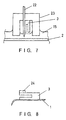
- Although the tuning fork type quartz oscillator has originally a Q-value of about 10,000 for resonance in air in the state where the probe is not attached, the Q-value in the above described embodiments is decreased to about 300 since the probe is attached to one side of the quartz oscillator. However, as shown in Fig. 8, with expecting that the
probe 1 is attached to one side of thequartz oscillator 3, if abalance weight 24 is attached to the other side thereof, the probe having a higher Q-value can be formed so that the detection sensibility can be increased. This method can be similarly applied also to the share force type scanning type near field interatomic force microscope. - Although the present invention has been described on the basis of various embodiments, it is needless to say that the present invention is not limited to these embodiments. Especially, with respect to a piezoelectric substance, although the tuning type quartz oscillator which is cheap and easily obtained is selected in the above embodiments, for example, the shape may be rod-shape, plate-shape, or cylinder-shape other than the tuning fork type. In principle, the shape thereof does not matter if it can oscillate the probe. Also, the material of the oscillator is not limited to the quartz. Any material exhibiting the piezoelectricity such as ZnO (zinc oxide), PZT (zircon/titanate) or a piezoelectric high molecular material may be applied similarly to the above-mentioned embodiments.
- The present invention is practiced as in the embodiments described above, and has effects as set forth below. A probe is attached to a piezoelectric substance, and interatomic force acting between the tip end of the probe and the surface of a sample is detected through a signal from electrodes provided on the piezoelectric substance, so that an optical system conventionally used for measurement of bending of a cantilever becomes unnecessary, whereby there are removed the restriction to a wavelength region for near field optical measurement, and the influence that an optical signal for bending measurement appears as noise in a signal of the near field optical measurement. Also, a troublesome operation such as alignment of an optical axis of detecting light for bending detection becomes unnecessary so that the measurement becomes easy.
- Further, since the place where the optical system used for the measurement of bending of the cantilever becomes empty, the freedom with respect to the arrangement of an optical system for the near field optical measurement is increased.
- Since the entire of a measurement system including the probe can be miniaturized, the measurement in a specific environment such as in a liquid, vacuum, or a low temperature container becomes easier than a conventional system.
Claims (9)
- A scanning type near field interatomic force microscope comprising a probe (1) made of a light transmitting material and having a sharpened tip portion with a transmitting hole for transmitting light, for simultaneously measuring a shape of a surface of a sample (2) and optical characteristics of a minute region of the surface of the sample (2) by scanning the surface of the sample (2) under a state where a distance between the tip portion of the probe (1) and the surface of the sample (2) is within an operation distance in which interatomic forces act between the tip portion of the probe (1) and the surface of the sample (2), characterized by comprising:wherein the oscillating means (6) is a drive circuit (6) for generating an AC drive signal for electrically driving the piezoelectric substance (3), the detection means (6) detects through the electrodes (5) current change of the AC drive signal which is caused by action of the interatomic forces, and the detection means outputs a detection signal for keeping the distance between the tip portion of the probe (1) and the surface of the sample (2) to be constant.a piezoelectric substance (3) integrally formed with the probe (1) and having electrodes (5);oscillating means (4, 6) for oscillating the piezoelectric substance (3) at a resonance frequency in a vertical or horizontal direction with respect to the surface of the sample (2);detection means (6, 7) for detecting change of resonance characteristics of the piezoelectric substance (3) caused by the interatomic force acting between the tip portion of the probe (1) and the surface of the sample (2) as change of electrical characteristics of the piezoelectric substance (3);control means (13) for keeping the distance between the tip portion of the probe (1) and the surface of the sample (2) to be constant on the basis of a detection signal outputted from the detection means (6, 7);
- A scanning type near field interatomic force microscope as claimed in claim 1, wherein the probe is hook-shaped and said piezoelectric substance (3) is oscillated at a resonance frequency in a vertical direction only with respect to the surface of the sample (2).
- A scanning type near field interatomic force microscope as claimed in claim 2, further comprising a sample container (17) enclosing the sample (2) and holding a liquid, the surface of the sample (2) being measured in a liquid environment in a state where the tip portion of the probe (1) is immersed in the liquid.
- A scanning type near field interatomic force microscope as claimed in claim 1, wherein the oscillating means (4) is a bimorph (4) for oscillating the piezoelectric substance (3) from the outside, the detection means (7) detects through the electrodes (5) that a voltage of the piezoelectric substance (3) caused from being oscillated by the bimorph (4) is changed by the interatomic forces, and the detection means outputs a detection signal for keeping the distance between the tip portion of the probe (1) and the surface of the sample (2) to be constant.
- A scanning type near field interatomic force microscope as claimed in claim 1, wherein the detection means (6, 7) comprises means for making a frequency of an oscillating signal of the oscillating means (4, 6) follow a resonance frequency of the piezoelectric substance (3) through comparison of a phase of the oscillating signal to a phase of an electrical signal detected through the electrodes (5) of the piezoelectric substance (3), the detection means outputs the detection signal by detecting the change of a resonance frequency caused by the action of the interatomic force, and the control means (13) controls the resonance frequency of the piezoelectric substance (3) to be constant so that the distance between the tip portion of the probe (1) and the surface of the sample (2) is kept constant.
- A scanning type near field interatomic force microscope as claimed in claim 1, wherein the piezoelectric substance (3) is of a tuning fork type quartz oscillator, the probe (1) is formed integrally with one arm of the tuning fork type quartz oscillator, and a balance weight for balancing against the probe (1) is formed integrally with the other arm.
- A scanning type near field interatomic force microscope according to claim 1 with a cover (23) covering the probe (22) and the top and a side surface of the piezoelectric substance (3), the surface of the sample (2) being measured in a liquid environment in a state where the tip portion of the probe (22) is immersed in a liquid filling the surface of the sample (2).
- A scanning type near field interatomic force microscope as claimed in claim 7, wherein the tip portion of the probe (22) is hook-shaped.
- A scanning type near field interatomic force microscope as claimed in claim 7, wherein the piezoeletric substance (3) is of a tuning fork type quartz oscillator, the probe (22) is formed integrally with one arm of the tuning type quartz oscillator, and a balance weight for balancing against the probe (22) is formed integrally with the other arm.
Applications Claiming Priority (3)
| Application Number | Priority Date | Filing Date | Title |
|---|---|---|---|
| JP3239696 | 1996-02-20 | ||
| JP8032396A JP2934739B2 (en) | 1996-02-20 | 1996-02-20 | Scanning near-field atomic force microscope |
| JP32396/96 | 1996-02-20 |
Publications (2)
| Publication Number | Publication Date |
|---|---|
| EP0791802A1 EP0791802A1 (en) | 1997-08-27 |
| EP0791802B1 true EP0791802B1 (en) | 2002-02-20 |
Family
ID=12357803
Family Applications (1)
| Application Number | Title | Priority Date | Filing Date |
|---|---|---|---|
| EP96120094A Expired - Lifetime EP0791802B1 (en) | 1996-02-20 | 1996-12-13 | Scanning type near field interatomic force microscope |
Country Status (4)
| Country | Link |
|---|---|
| US (1) | US5939623A (en) |
| EP (1) | EP0791802B1 (en) |
| JP (1) | JP2934739B2 (en) |
| DE (1) | DE69619357T2 (en) |
Families Citing this family (33)
| Publication number | Priority date | Publication date | Assignee | Title |
|---|---|---|---|---|
| JP3202646B2 (en) * | 1997-04-09 | 2001-08-27 | セイコーインスツルメンツ株式会社 | Scanning probe microscope |
| US6466537B1 (en) * | 1998-03-20 | 2002-10-15 | Seiko Instruments Inc. | Recording apparatus |
| US6138502A (en) * | 1998-06-05 | 2000-10-31 | Marburg Technology, Inc. | Glide head for detecting defects on a disk surface |
| US6240771B1 (en) * | 1999-02-25 | 2001-06-05 | Franz J. Giessibl | Device for noncontact intermittent contact scanning of a surface and a process therefore |
| JP4044241B2 (en) * | 1999-05-24 | 2008-02-06 | 日本分光株式会社 | Probe microscope |
| DE19925431C2 (en) * | 1999-06-02 | 2002-11-07 | Ind Tech Res Inst | Optical near-field scanning microscope |
| AU6256300A (en) * | 1999-07-20 | 2001-02-05 | Dmitri N. Davydov | High q-factor micro tuning fork by thin optical fiber for nsom |
| US6405584B1 (en) * | 1999-10-05 | 2002-06-18 | Agere Systems Guardian Corp. | Probe for scanning probe microscopy and related methods |
| JP2002286614A (en) * | 2001-03-28 | 2002-10-03 | Toyota Motor Corp | Method of observing sample in liquid using scanning probe microscope |
| EP1256962A1 (en) * | 2001-05-11 | 2002-11-13 | Institut De Microtechnique | Actuating and sensing device for scanning probe microscopes |
| US6668628B2 (en) | 2002-03-29 | 2003-12-30 | Xerox Corporation | Scanning probe system with spring probe |
| US6866255B2 (en) * | 2002-04-12 | 2005-03-15 | Xerox Corporation | Sputtered spring films with low stress anisotropy |
| US7434476B2 (en) * | 2003-05-07 | 2008-10-14 | Califronia Institute Of Technology | Metallic thin film piezoresistive transduction in micromechanical and nanomechanical devices and its application in self-sensing SPM probes |
| US7015584B2 (en) * | 2003-07-08 | 2006-03-21 | Xerox Corporation | High force metal plated spring structure |
| JP2006039260A (en) * | 2004-07-28 | 2006-02-09 | Sii Nanotechnology Inc | Method for removing particle of photomask by using atomic force microscope |
| US7230440B2 (en) * | 2004-10-21 | 2007-06-12 | Palo Alto Research Center Incorporated | Curved spring structure with elongated section located under cantilevered section |
| US8330485B2 (en) * | 2004-10-21 | 2012-12-11 | Palo Alto Research Center Incorporated | Curved spring structure with downturned tip |
| US8601608B2 (en) | 2005-03-31 | 2013-12-03 | Japan Science And Technology Agency | Cantilever for scanning probe microscope and scanning probe microscope equipped with it |
| JP4987284B2 (en) * | 2005-11-10 | 2012-07-25 | エスアイアイ・ナノテクノロジー株式会社 | Cantilever holder for liquid and scanning probe microscope |
| JP2008122325A (en) * | 2006-11-15 | 2008-05-29 | Jeol Ltd | Scanning probe microscope |
| JP4899162B2 (en) * | 2007-07-17 | 2012-03-21 | 独立行政法人産業技術総合研究所 | Scanning probe microscope probe and scanning probe microscope using the same |
| JP4910949B2 (en) * | 2007-08-29 | 2012-04-04 | 株式会社島津製作所 | Method for analyzing samples in liquid |
| TWI434142B (en) * | 2008-07-25 | 2014-04-11 | Nanya Technology Corp | Lithography apparatus with a fiber module |
| IL197329A0 (en) * | 2009-03-01 | 2009-12-24 | David Lewis | A scanned probe microscope without interference or geometric constraint for single or multiple probe operation in air or liquid |
| WO2010123120A1 (en) * | 2009-04-24 | 2010-10-28 | 並木精密宝石株式会社 | Immersion measurement probe, cantilever, and immersion measurement method |
| KR101065981B1 (en) * | 2009-05-20 | 2011-09-19 | 인하대학교 산학협력단 | Mechanically-coupled vibrating tuning fork-scanning probe system |
| RU2494406C2 (en) * | 2009-12-14 | 2013-09-27 | Закрытое Акционерное Общество "Нанотехнология Мдт" | Scanning probe microscope |
| US9110093B2 (en) | 2011-11-15 | 2015-08-18 | National University Corporation Kanazawa University | Sealed AFM cell |
| CN102621351B (en) * | 2012-04-20 | 2015-03-11 | 中国科学院苏州纳米技术与纳米仿生研究所 | Scanning near-field optical microscope |
| WO2014006734A1 (en) * | 2012-07-06 | 2014-01-09 | 株式会社日立製作所 | Force probe microscope and height distribution measurement method |
| JP6322295B2 (en) * | 2014-12-24 | 2018-05-09 | 株式会社日立製作所 | Scanning probe microscope and its sample holder |
| CN104777331B (en) * | 2015-04-16 | 2017-03-29 | 中国科学院半导体研究所 | Optical microscope for scanning near field imaging system based on quartz tuning-fork |
| CN113092826B (en) * | 2021-03-05 | 2023-04-07 | 中山大学 | Scanning probe microscope system and measuring method thereof |
Family Cites Families (13)
| Publication number | Priority date | Publication date | Assignee | Title |
|---|---|---|---|---|
| DE3771711D1 (en) | 1987-05-12 | 1991-08-29 | Ibm | ATOMARIC POWER MICROSCOPE WITH OSCILLATING QUARTZ. |
| US4935634A (en) * | 1989-03-13 | 1990-06-19 | The Regents Of The University Of California | Atomic force microscope with optional replaceable fluid cell |
| JPH04102008A (en) | 1990-08-21 | 1992-04-03 | Brother Ind Ltd | Interatomic force microscope |
| JP3074357B2 (en) * | 1991-10-03 | 2000-08-07 | セイコーインスツルメンツ株式会社 | Micro surface observation device |
| US5254854A (en) * | 1991-11-04 | 1993-10-19 | At&T Bell Laboratories | Scanning microscope comprising force-sensing means and position-sensitive photodetector |
| JP2704601B2 (en) * | 1993-04-12 | 1998-01-26 | セイコーインスツルメンツ株式会社 | Scanning near-field atomic force microscope, probe used in the microscope, and method of manufacturing the probe |
| US5354985A (en) * | 1993-06-03 | 1994-10-11 | Stanford University | Near field scanning optical and force microscope including cantilever and optical waveguide |
| US5389779A (en) * | 1993-07-29 | 1995-02-14 | At&T Corp. | Method and apparatus for near-field, scanning, optical microscopy by reflective, optical feedback |
| US5513168A (en) * | 1993-10-19 | 1996-04-30 | Seiko Instruments Inc. | Optical information read/write apparatus |
| JP3425615B2 (en) * | 1994-03-24 | 2003-07-14 | 科学技術庁長官官房会計課長 | Scanning near-field atomic force microscope |
| US5548113A (en) * | 1994-03-24 | 1996-08-20 | Trustees Of Boston University | Co-axial detection and illumination with shear force dithering in a near-field scanning optical microscope |
| GB2289759B (en) * | 1994-05-11 | 1996-05-22 | Khaled Karrau | Coupled oscillator scanning imager |
| JP2936311B2 (en) * | 1994-09-09 | 1999-08-23 | セイコーインスツルメンツ株式会社 | Scanning near-field atomic force microscope with in-liquid observation function |
-
1996
- 1996-02-20 JP JP8032396A patent/JP2934739B2/en not_active Expired - Fee Related
- 1996-12-13 US US08/764,214 patent/US5939623A/en not_active Expired - Lifetime
- 1996-12-13 DE DE69619357T patent/DE69619357T2/en not_active Expired - Lifetime
- 1996-12-13 EP EP96120094A patent/EP0791802B1/en not_active Expired - Lifetime
Also Published As
| Publication number | Publication date |
|---|---|
| US5939623A (en) | 1999-08-17 |
| DE69619357D1 (en) | 2002-03-28 |
| JP2934739B2 (en) | 1999-08-16 |
| EP0791802A1 (en) | 1997-08-27 |
| JPH09229948A (en) | 1997-09-05 |
| DE69619357T2 (en) | 2002-08-14 |
Similar Documents
| Publication | Publication Date | Title |
|---|---|---|
| EP0791802B1 (en) | Scanning type near field interatomic force microscope | |
| CA2171188C (en) | Resonant guage with microbeam driven in constant electric field | |
| EP0864899B1 (en) | Scanning near-field optical microscope | |
| Brunner et al. | Distance control in near-field optical microscopy with piezoelectrical shear-force detection suitable for imaging in liquids | |
| US5760300A (en) | Scanning probe microscope | |
| EP0871006B1 (en) | Scanning probe microscope | |
| Maenaka et al. | Analysis of a highly sensitive silicon gyroscope with cantilever beam as vibrating mass | |
| JP3511361B2 (en) | Scanning probe microscope | |
| US5507179A (en) | Synchronous sampling scanning force microscope | |
| US20020092359A1 (en) | Sensor apparatus and cantilever for it | |
| US5990477A (en) | Apparatus for machining, recording, and reproducing, using scanning probe microscope | |
| US7730770B2 (en) | Scanning probe microscope | |
| RU2321084C2 (en) | Probe for the probe microscope which uses transparent substrates, the probe microscope and the method for manufacturing the probe | |
| US5886532A (en) | Nanometer distance regulation using electromechanical power dissipation | |
| WO2011016256A1 (en) | Cantilever excitation device and scanning probe microscope | |
| JPH09329606A (en) | Scanning near field microscope with in-liquid observation function | |
| JPH0821845A (en) | Sample measuring probe device | |
| US7854015B2 (en) | Method for measuring the force of interaction in a scanning probe microscope | |
| JPH10267950A (en) | Lateral-excitation frictional-force microscope | |
| JPH0989911A (en) | Compound-oscillator scanning imager | |
| JP2000009624A (en) | Scanning probe microscope | |
| JPH10282126A (en) | Scanning probe microscope and its sample observation method | |
| JPH10160742A (en) | Sample holder of scanning probe microscope |
Legal Events
| Date | Code | Title | Description |
|---|---|---|---|
| PUAI | Public reference made under article 153(3) epc to a published international application that has entered the european phase |
Free format text: ORIGINAL CODE: 0009012 |
|
| AK | Designated contracting states |
Kind code of ref document: A1 Designated state(s): DE FR |
|
| 17P | Request for examination filed |
Effective date: 19971010 |
|
| 17Q | First examination report despatched |
Effective date: 20000207 |
|
| GRAG | Despatch of communication of intention to grant |
Free format text: ORIGINAL CODE: EPIDOS AGRA |
|
| GRAG | Despatch of communication of intention to grant |
Free format text: ORIGINAL CODE: EPIDOS AGRA |
|
| GRAH | Despatch of communication of intention to grant a patent |
Free format text: ORIGINAL CODE: EPIDOS IGRA |
|
| GRAH | Despatch of communication of intention to grant a patent |
Free format text: ORIGINAL CODE: EPIDOS IGRA |
|
| GRAA | (expected) grant |
Free format text: ORIGINAL CODE: 0009210 |
|
| AK | Designated contracting states |
Kind code of ref document: B1 Designated state(s): DE FR |
|
| PG25 | Lapsed in a contracting state [announced via postgrant information from national office to epo] |
Ref country code: FR Free format text: LAPSE BECAUSE OF FAILURE TO SUBMIT A TRANSLATION OF THE DESCRIPTION OR TO PAY THE FEE WITHIN THE PRESCRIBED TIME-LIMIT Effective date: 20020220 |
|
| REF | Corresponds to: |
Ref document number: 69619357 Country of ref document: DE Date of ref document: 20020328 |
|
| EN | Fr: translation not filed | ||
| PLBE | No opposition filed within time limit |
Free format text: ORIGINAL CODE: 0009261 |
|
| STAA | Information on the status of an ep patent application or granted ep patent |
Free format text: STATUS: NO OPPOSITION FILED WITHIN TIME LIMIT |
|
| 26N | No opposition filed |
Effective date: 20021121 |
|
| PGFP | Annual fee paid to national office [announced via postgrant information from national office to epo] |
Ref country code: DE Payment date: 20091222 Year of fee payment: 14 |
|
| REG | Reference to a national code |
Ref country code: DE Ref legal event code: R119 Ref document number: 69619357 Country of ref document: DE Effective date: 20110701 |
|
| PG25 | Lapsed in a contracting state [announced via postgrant information from national office to epo] |
Ref country code: DE Free format text: LAPSE BECAUSE OF NON-PAYMENT OF DUE FEES Effective date: 20110701 |