EP0791551A2 - Web feeder centering method and apparatus - Google Patents
Web feeder centering method and apparatus Download PDFInfo
- Publication number
- EP0791551A2 EP0791551A2 EP97102809A EP97102809A EP0791551A2 EP 0791551 A2 EP0791551 A2 EP 0791551A2 EP 97102809 A EP97102809 A EP 97102809A EP 97102809 A EP97102809 A EP 97102809A EP 0791551 A2 EP0791551 A2 EP 0791551A2
- Authority
- EP
- European Patent Office
- Prior art keywords
- edge portion
- width
- belt feeder
- path
- along
- Prior art date
- Legal status (The legal status is an assumption and is not a legal conclusion. Google has not performed a legal analysis and makes no representation as to the accuracy of the status listed.)
- Withdrawn
Links
Images



Classifications
-
- B—PERFORMING OPERATIONS; TRANSPORTING
- B29—WORKING OF PLASTICS; WORKING OF SUBSTANCES IN A PLASTIC STATE IN GENERAL
- B29D—PRODUCING PARTICULAR ARTICLES FROM PLASTICS OR FROM SUBSTANCES IN A PLASTIC STATE
- B29D30/00—Producing pneumatic or solid tyres or parts thereof
- B29D30/06—Pneumatic tyres or parts thereof (e.g. produced by casting, moulding, compression moulding, injection moulding, centrifugal casting)
- B29D30/38—Textile inserts, e.g. cord or canvas layers, for tyres; Treatment of inserts prior to building the tyre
- B29D30/44—Stretching or treating the layers before application on the drum
-
- B—PERFORMING OPERATIONS; TRANSPORTING
- B65—CONVEYING; PACKING; STORING; HANDLING THIN OR FILAMENTARY MATERIAL
- B65G—TRANSPORT OR STORAGE DEVICES, e.g. CONVEYORS FOR LOADING OR TIPPING, SHOP CONVEYOR SYSTEMS OR PNEUMATIC TUBE CONVEYORS
- B65G47/00—Article or material-handling devices associated with conveyors; Methods employing such devices
- B65G47/02—Devices for feeding articles or materials to conveyors
- B65G47/04—Devices for feeding articles or materials to conveyors for feeding articles
- B65G47/12—Devices for feeding articles or materials to conveyors for feeding articles from disorderly-arranged article piles or from loose assemblages of articles
- B65G47/14—Devices for feeding articles or materials to conveyors for feeding articles from disorderly-arranged article piles or from loose assemblages of articles arranging or orientating the articles by mechanical or pneumatic means during feeding
-
- B—PERFORMING OPERATIONS; TRANSPORTING
- B65—CONVEYING; PACKING; STORING; HANDLING THIN OR FILAMENTARY MATERIAL
- B65H—HANDLING THIN OR FILAMENTARY MATERIAL, e.g. SHEETS, WEBS, CABLES
- B65H23/00—Registering, tensioning, smoothing or guiding webs
- B65H23/02—Registering, tensioning, smoothing or guiding webs transversely
- B65H23/032—Controlling transverse register of web
-
- B—PERFORMING OPERATIONS; TRANSPORTING
- B65—CONVEYING; PACKING; STORING; HANDLING THIN OR FILAMENTARY MATERIAL
- B65H—HANDLING THIN OR FILAMENTARY MATERIAL, e.g. SHEETS, WEBS, CABLES
- B65H35/00—Delivering articles from cutting or line-perforating machines; Article or web delivery apparatus incorporating cutting or line-perforating devices, e.g. adhesive tape dispensers
- B65H35/0006—Article or web delivery apparatus incorporating cutting or line-perforating devices
- B65H35/006—Article or web delivery apparatus incorporating cutting or line-perforating devices with means for delivering a predetermined length of tape
-
- B—PERFORMING OPERATIONS; TRANSPORTING
- B65—CONVEYING; PACKING; STORING; HANDLING THIN OR FILAMENTARY MATERIAL
- B65H—HANDLING THIN OR FILAMENTARY MATERIAL, e.g. SHEETS, WEBS, CABLES
- B65H9/00—Registering, e.g. orientating, articles; Devices therefor
- B65H9/10—Pusher and like movable registers; Pusher or gripper devices which move articles into registered position
- B65H9/103—Pusher and like movable registers; Pusher or gripper devices which move articles into registered position acting by friction or suction on the article for pushing or pulling it into registered position, e.g. against a stop
- B65H9/106—Pusher and like movable registers; Pusher or gripper devices which move articles into registered position acting by friction or suction on the article for pushing or pulling it into registered position, e.g. against a stop using rotary driven elements as part acting on the article
-
- B—PERFORMING OPERATIONS; TRANSPORTING
- B29—WORKING OF PLASTICS; WORKING OF SUBSTANCES IN A PLASTIC STATE IN GENERAL
- B29D—PRODUCING PARTICULAR ARTICLES FROM PLASTICS OR FROM SUBSTANCES IN A PLASTIC STATE
- B29D30/00—Producing pneumatic or solid tyres or parts thereof
- B29D30/06—Pneumatic tyres or parts thereof (e.g. produced by casting, moulding, compression moulding, injection moulding, centrifugal casting)
- B29D30/38—Textile inserts, e.g. cord or canvas layers, for tyres; Treatment of inserts prior to building the tyre
- B29D30/44—Stretching or treating the layers before application on the drum
- B29D2030/4406—Adjusting the positions of the layers
- B29D2030/4418—Adjusting the positions of the layers laterally, e.g. sideways
-
- B—PERFORMING OPERATIONS; TRANSPORTING
- B29—WORKING OF PLASTICS; WORKING OF SUBSTANCES IN A PLASTIC STATE IN GENERAL
- B29D—PRODUCING PARTICULAR ARTICLES FROM PLASTICS OR FROM SUBSTANCES IN A PLASTIC STATE
- B29D30/00—Producing pneumatic or solid tyres or parts thereof
- B29D30/06—Pneumatic tyres or parts thereof (e.g. produced by casting, moulding, compression moulding, injection moulding, centrifugal casting)
- B29D30/38—Textile inserts, e.g. cord or canvas layers, for tyres; Treatment of inserts prior to building the tyre
- B29D30/44—Stretching or treating the layers before application on the drum
- B29D2030/4468—Holding the layers
- B29D2030/4487—Holding the layers by using mechanical means, e.g. grippers or pressing bars
-
- B—PERFORMING OPERATIONS; TRANSPORTING
- B65—CONVEYING; PACKING; STORING; HANDLING THIN OR FILAMENTARY MATERIAL
- B65H—HANDLING THIN OR FILAMENTARY MATERIAL, e.g. SHEETS, WEBS, CABLES
- B65H2511/00—Dimensions; Position; Numbers; Identification; Occurrences
- B65H2511/10—Size; Dimensions
- B65H2511/12—Width
-
- B—PERFORMING OPERATIONS; TRANSPORTING
- B65—CONVEYING; PACKING; STORING; HANDLING THIN OR FILAMENTARY MATERIAL
- B65H—HANDLING THIN OR FILAMENTARY MATERIAL, e.g. SHEETS, WEBS, CABLES
- B65H2511/00—Dimensions; Position; Numbers; Identification; Occurrences
- B65H2511/20—Location in space
- B65H2511/24—Irregularities, e.g. in orientation or skewness
-
- B—PERFORMING OPERATIONS; TRANSPORTING
- B65—CONVEYING; PACKING; STORING; HANDLING THIN OR FILAMENTARY MATERIAL
- B65H—HANDLING THIN OR FILAMENTARY MATERIAL, e.g. SHEETS, WEBS, CABLES
- B65H2511/00—Dimensions; Position; Numbers; Identification; Occurrences
- B65H2511/50—Occurence
- B65H2511/515—Absence
- B65H2511/518—Particular portion of element
-
- B—PERFORMING OPERATIONS; TRANSPORTING
- B65—CONVEYING; PACKING; STORING; HANDLING THIN OR FILAMENTARY MATERIAL
- B65H—HANDLING THIN OR FILAMENTARY MATERIAL, e.g. SHEETS, WEBS, CABLES
- B65H2801/00—Application field
- B65H2801/93—Tyres
Definitions
- the present invention relates to a method and apparatus for a belt feeder. More particularly, the present invention relates to a method and apparatus as applied to a belt feeder used for the molding of tires.
- the belt feeder When a belt feeder is utilized for transporting material from one position to another position, particularly via a cutter apparatus, it is important that the material be appropriately centered on the belt feeder.
- the belt feeder transports the material through a cutter member which cuts the material into desired patterns.
- the patterns of material are then applied from the end of the belt feeder into a tray for attachment which further processes the tire material and brings the same to the tire-molding apparatus.
- Figure 6 is a front view of conventional centering apparatus.
- a frame 1 is provided having a conveyor 2 mounted thereon.
- the conveyor 2 is a centering conveyor which can be moved along a threaded shaft 10 by manually rotating the handle 9 arranged at one end of the shaft 10.
- the material to be centered is designated by W.
- This material is supported by a roller 5 and has both edges restricted by a plurality of pairs of vertical or guide rollers 6 arranged in the direction perpendicular to the roller 5 to maintain the material at the center position. Accordingly, the type of prior art shown in Figure 6 restricts the movement of both edges of the material W as it is transported along the belt feeder.
- FIG 7 is a front view of such apparatus.
- the apparatus illustrated in Figure 7 again has a roller 5 and a material W, but only one edge of the material W is restricted by a vertical roller 7. The other edge of the material W moves along the path between photodetector elements 19 and 20 arranged above and below the roller 5.
- the vertical roller 7 is mounted on a conveyor 2 and may be moved left or right on a guide 4 by the driving means of a servomotor 11.
- the servomotor 11 rotates a coupling 12 and a rack-and-pinion arrangement 13 for moving the vertical roller 7 as the width of the material W fluctuates.
- a photosensor amplifier 21, coupled to photodetectors 19 and 20, is provided which will produce an output for driving the servomotor 11 in the appropriate direction.
- the photosensor elements 19 and 20 are of the transmittive type. If the sensor 19 is of the reflective type, a reflection plate may be arranged at the position of the photoelectric element 20 instead.
- It a further object of the present invention to provide a method and apparatus which senses the overall width of the material over its entire length and which reduces the number of elements that have to be mechanically adjusted when different materials are used.
- a method for centering material on a belt feeder having a center position includes the steps of moving the material along a desired path on the belt feeder. Measuring the width of the front-edge portion of the material is carried out at a preselected location along the path using edge-position control. Also, the position coordinates of both side edges are measured at the same preselected location using center-position control after the front-edge portion has moved past such location. The center position of the material is then calculated based on the position coordinates. Finally, the material is moved in a direction to have the center position of the material coincide with the center position of the belt feeder, if such movement is necessary.
- the material has a rear-edge portion and the width of the rear-edge portion is measured at the same preselected location as the front-edge portion, also using edge-position control when the rear-edge portion reaches the location.
- An embodiment of the present invention includes apparatus for centering material on a belt feeder which has a center position.
- Conveyor means are provided for moving the material along a desired path on the belt feeder.
- Means for measuring the width of the front-edge portion of the material at a preselected location is provided using edge-position control.
- Means are also included for measuring the position coordinates of both of the edges of the material using center-position control after the front-edge portion has moved past the measuring location.
- Means are included for calculating the center position of the material based on the position coordinates of the two edges.
- the conveyor is moved in a direction to have the center position of the material coincide with the center position of the belt feeder, if such movement is necessary.
- a cutter is arranged along the path on the belt feeder along which the material moves.
- the cutter has an entry and an exit side.
- First guiding means are arranged at the entry side of the cutter for centering the material on the belt feeder, and second guiding means are arranged at the exit side of the cutter for aligning at least one of the side edges of the material along a predetermined path.
- belt material for the tire-molding process is fed from the right side of Figure 1 along the roller 5 between restricting guide rollers 6.
- the guide rollers 6 are paired at the right-hand and left-hand sides of the centering conveyor 2, as best seen in Figure 3. Accordingly, the material is already substantially centered in advance as it moves along the centering conveyor 2.
- the material is guided to the second guide roller 7, which is arranged at only one edge of the material.
- a cutter 8 is arranged substantially diagonally across the belt feeder and has an entry side at the right-hand portion, as shown in Figure 1, and an exit side at the left-hand portion.
- the center of the material being fed along the belt roller coincide with the center of the belt roller.
- the center of the belt roller is meant a central axis equidistant between the edges of the roller.
- the center position of the material is meant an axis of the material arranged parallel to the side edges and equidistant from each of the side edges.
- the material After the material leaves the exit side of the cutter 8, it proceeds along the predetermined path toward the tray 3 for attachment, which is a further belt arrangement, best seen in Figure 2, for taking the cut portions of the material and transporting them further to the tire-molding apparatus.
- a one-dimensional image sensor 14 which is arranged between the centering conveyor 2 and the tray 3 for attachment .
- the centering conveyor 2 is moved horizontally along the guide 4, as best seen in Figure 3, by means of a servomotor 11, a coupling 12, and a rack-and-pinion arrangement 13. It is clear that the various elements of all of the figures which are the same are identified by the same numeral.
- the coordinate signals produced from the one-dimensional image sensor 14 is applied to the input of a controller 17 by means of an image sensor amplifier 16.
- the required movement of the actuator is determined by a calculation process (which will discussed with respect to the flow diagram of Figure 5) in order to supply the signal to the servoamplifier 18 which controls the motor 11.
- the sensor section of the one-dimensional image sensor 14 is a solid-state image component in which 1024, 2048, or 4096 photocells arranged at a constant distance from the material.
- the material W having been cut by the cutter 8 has a front-edge portion, shown from points A-B of Subfigure 4(a).
- the front-edge portion will first move into the location of the photosensor 14 and the varying width will develop a plurality of light and dark patterns from the output of the sensor.
- the apparatus will perform the edge-position control (EPC) method to match a coordinate of the single, constant-edge portion with the coordinate for the rear-edge portion that may have preceded the front-edge portion now passing the sensor 14.
- EPC edge-position control
- the control method is automatically switched to the EPC method, having a standard value on the one side available.
- the standard value used at this time uses the coordinate data around the final position of the section controlled by the CPC method to control up to the point D of Subfigure 4(d).
- the standard value used when the EPC method for the next material starts from the point E is the coordinate position near the position C at the rear-edge portion of the previous material.
- the alignment of one edge of the material can be obtained by the second guide roller 7. Also, based on the information relative to the position and the width of the material measured by the sensor 14, the material can be conveyed to the adhesive belt or tray 3 for attachment so that the center position of the material is matched on the centerline of the belt drum utilized for the tray 3.
- the controller 17 drives the centering conveyor 2 in the horizontal direction along the shaft 4, according to the flow control illustrated in Figure 5. In this way the center position of the material will be aligned with the centerline of the feeder belt drum.
- the controller 17 calculates the center position P k of the dark section at step P2.
- the next step is to calculate the deviation ⁇ between P k and the value predetermined at the step P3 (the home position P a ).
- the controller 17 sends an order to the servomotor 11 to drive the right side at step P7 and will control such movement without interruption until the deviation ⁇ equals zero.
- the controller 17 will determine at step P5 whether the deviation ⁇ equals zero or not. If the deviation ⁇ is not zero, the controller 17 will send an order to the servomotor 11 to drive the left side at the step P6 and will control such movement without operation until the ⁇ again equals zero. When the deviation ⁇ equals zero, the controller 17 continues to control.
- the sensor 14 faces downward so that the surface will rarely catch any dust.
- the light source 15 even if there is more or less dust, is not a problem as long as the photodetector element can recognize the light and dark portions.
- the method and apparatus incorporating the principles of the present invention can be used for many applications. For example, it can control the upstream process of the material and improve quality control thereof by monitoring the data measured relating to the material width. It could also be used effectively as means for detecting any material that is off-center by a substantial amount.
- the method and apparatus incorporating the principles of the present invention can note this by the monitoring function since one can quickly realize when the material has a width which exceeds the maximum possible width set in the controller.
- COF conicity force
- the entire width of the material can be detected and controlled without interruption. Stable precision for centering a material is provided. Furthermore, because it does not require a mechanical changing of the position of the detection means when the materials are changed, the possibility of decreased precision in measurement is quite low. Thus, the centering apparatus is exceedingly easy to maintain.
Landscapes
- Engineering & Computer Science (AREA)
- Mechanical Engineering (AREA)
- Textile Engineering (AREA)
- Tyre Moulding (AREA)
Abstract
A method and apparatus are provided for positioning a sheets of material (W) on a belt feeder for transporting the material through a cutter (8) toward a tire-processing apparatus. The material has a front-edge portion which is centered by using edge-position control (EPC), and side portions which are centered by using center-position control (CPC). Also, the material as cut will have a rear-edge portion, the centering position of which is controlled by edge-position control.
Description
- The present invention relates to a method and apparatus for a belt feeder. More particularly, the present invention relates to a method and apparatus as applied to a belt feeder used for the molding of tires.
- When a belt feeder is utilized for transporting material from one position to another position, particularly via a cutter apparatus, it is important that the material be appropriately centered on the belt feeder. For preparing material for tire molding, for example, the belt feeder transports the material through a cutter member which cuts the material into desired patterns. The patterns of material are then applied from the end of the belt feeder into a tray for attachment which further processes the tire material and brings the same to the tire-molding apparatus.
- Conventional methods have been utilized for centering the material being transported along a belt feeder. One method restricts both edges of the material using mechanical guide rollers. Another method restricts only one edge of the material and detects the opposite edge of the material by means of a photoelectric sensor. This arrangement will measure the width fluctuation according to changes in the output voltage of the photoelectric sensor. This arrangement will drive a conveyor in the direction of the width of the material so that the center position of the material will match or coincide with the center position or centerline of the belt roller.
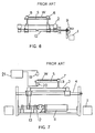
- Referring to Figure 6, one such prior art device is shown. Figure 6 is a front view of conventional centering apparatus. In Figure 6, a frame 1 is provided having a
conveyor 2 mounted thereon. Theconveyor 2 is a centering conveyor which can be moved along a threadedshaft 10 by manually rotating thehandle 9 arranged at one end of theshaft 10. - The material to be centered is designated by W. This material is supported by a
roller 5 and has both edges restricted by a plurality of pairs of vertical orguide rollers 6 arranged in the direction perpendicular to theroller 5 to maintain the material at the center position. Accordingly, the type of prior art shown in Figure 6 restricts the movement of both edges of the material W as it is transported along the belt feeder. - A second conventional arrangement is shown in Figure 7, which is a front view of such apparatus. The apparatus illustrated in Figure 7 again has a
roller 5 and a material W, but only one edge of the material W is restricted by avertical roller 7. The other edge of the material W moves along the path betweenphotodetector elements roller 5. - The
vertical roller 7 is mounted on aconveyor 2 and may be moved left or right on aguide 4 by the driving means of a servomotor 11. The servomotor 11 rotates acoupling 12 and a rack-and-pinion arrangement 13 for moving thevertical roller 7 as the width of the material W fluctuates. In Figure 7, aphotosensor amplifier 21, coupled tophotodetectors photosensor elements sensor 19 is of the reflective type, a reflection plate may be arranged at the position of thephotoelectric element 20 instead. - These conventional methods suffer from several difficulties. It is clear that when the mechanical guide-roller arrangement of Figure 6 is used, for example, if the width of the material is wider than the distance between the rollers, it is very difficult to straighten out the material evenly. When the apparatus uses a photoelectric sensor in order to compensate for the width fluctuation of the material, it is necessary to adjust the photoelectric sensor so as to maintain the material perpendicular to the surface of the conveyor and parallel to the guide roller. Also, when the width of the material is changed, it is also necessary to change the mounting position of the photoelectric sensor. Clearly, there is a further drawback that the photodetector elements or the reflection plate or both always have to kept clean as well.
- It is therefore an object of the present invention to provide a belt-roller centering method and apparatus which will overcome the problems presented by the conventional solutions.
- It a further object of the present invention to provide a method and apparatus which senses the overall width of the material over its entire length and which reduces the number of elements that have to be mechanically adjusted when different materials are used.
- In accordance with the present invention, a method for centering material on a belt feeder having a center position is provided. The material has side edges and a front-edge portion, and includes the steps of moving the material along a desired path on the belt feeder. Measuring the width of the front-edge portion of the material is carried out at a preselected location along the path using edge-position control. Also, the position coordinates of both side edges are measured at the same preselected location using center-position control after the front-edge portion has moved past such location. The center position of the material is then calculated based on the position coordinates. Finally, the material is moved in a direction to have the center position of the material coincide with the center position of the belt feeder, if such movement is necessary.
- In a further method for carrying out the present invention, the material has a rear-edge portion and the width of the rear-edge portion is measured at the same preselected location as the front-edge portion, also using edge-position control when the rear-edge portion reaches the location.
- An embodiment of the present invention includes apparatus for centering material on a belt feeder which has a center position. Conveyor means are provided for moving the material along a desired path on the belt feeder. Means for measuring the width of the front-edge portion of the material at a preselected location is provided using edge-position control. Means are also included for measuring the position coordinates of both of the edges of the material using center-position control after the front-edge portion has moved past the measuring location. Means are included for calculating the center position of the material based on the position coordinates of the two edges. Finally, the conveyor is moved in a direction to have the center position of the material coincide with the center position of the belt feeder, if such movement is necessary.
- In a further embodiment of the present invention, a cutter is arranged along the path on the belt feeder along which the material moves. The cutter has an entry and an exit side. First guiding means are arranged at the entry side of the cutter for centering the material on the belt feeder, and second guiding means are arranged at the exit side of the cutter for aligning at least one of the side edges of the material along a predetermined path.
- The above and other objects, features, and advantages of the present invention will become more apparent from the following detailed description taken with the accompanying drawings, in which:
- Figure 1 is a plan view of a preferred embodiment of the centering apparatus incorporating the principles of the present invention;
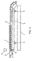
- Figure 2 is a side view of the apparatus of Figure 1;
- Figure 3 is a front view of the apparatus of Figure 1;
- Figure 4, containing Subfigures 4(a)-4(e) schematically shows the control-centering process carried out by the embodiment of Figure 1;
- Figure 5 is a flow diagram showing the method used by the apparatus of Figure 1;
- Figure 6 is a front view of conventional centering apparatus; and
- Figure 7 is a front view of a second conventional centering apparatus.
- Referring to the drawings, and more particularly to Figures 1-3, belt material for the tire-molding process is fed from the right side of Figure 1 along the
roller 5 betweenrestricting guide rollers 6. It can be seen that theguide rollers 6 are paired at the right-hand and left-hand sides of the centeringconveyor 2, as best seen in Figure 3. Accordingly, the material is already substantially centered in advance as it moves along the centeringconveyor 2. The material is guided to thesecond guide roller 7, which is arranged at only one edge of the material. - A
cutter 8 is arranged substantially diagonally across the belt feeder and has an entry side at the right-hand portion, as shown in Figure 1, and an exit side at the left-hand portion. - As noted above, it is an object of the present invention to have the center of the material being fed along the belt roller coincide with the center of the belt roller. By "the center of the belt roller" is meant a central axis equidistant between the edges of the roller. Similarly, by "the center position of the material" is meant an axis of the material arranged parallel to the side edges and equidistant from each of the side edges.
- After the material leaves the exit side of the
cutter 8, it proceeds along the predetermined path toward thetray 3 for attachment, which is a further belt arrangement, best seen in Figure 2, for taking the cut portions of the material and transporting them further to the tire-molding apparatus. - At the end of the belt roller is a one-
dimensional image sensor 14 which is arranged between the centeringconveyor 2 and thetray 3 for attachment . The centeringconveyor 2 is moved horizontally along theguide 4, as best seen in Figure 3, by means of a servomotor 11, acoupling 12, and a rack-and-pinion arrangement 13. It is clear that the various elements of all of the figures which are the same are identified by the same numeral. - Instead of using the servomechanism 11, it is evident that the manual control, shown in Figure 6, can be used for shifting the conveyor along the
shaft 4 as well. - The coordinate signals produced from the one-
dimensional image sensor 14 is applied to the input of acontroller 17 by means of animage sensor amplifier 16. The required movement of the actuator is determined by a calculation process (which will discussed with respect to the flow diagram of Figure 5) in order to supply the signal to theservoamplifier 18 which controls the motor 11. - The sensor section of the one-
dimensional image sensor 14 is a solid-state image component in which 1024, 2048, or 4096 photocells arranged at a constant distance from the material. - Referring to Figure 4, it can be seen that the material W, having been cut by the
cutter 8, has a front-edge portion, shown from points A-B of Subfigure 4(a). The front-edge portion will first move into the location of thephotosensor 14 and the varying width will develop a plurality of light and dark patterns from the output of the sensor. As the front-edge portion moves past the preselected location of thesensor 14, the apparatus will perform the edge-position control (EPC) method to match a coordinate of the single, constant-edge portion with the coordinate for the rear-edge portion that may have preceded the front-edge portion now passing thesensor 14. - It is also possible to set information in advance on the width of the material in the
controller 17 by selecting the code number of the material at the initial passing of such material through theimage sensor 14. It is also possible to manually move the conveyor to start the material close to the center position thereof. After the material is moved into thetray 3 for attachment and the point B in Subfigure 4(a) reaches the location of thesensor 14, the coordinate data increase on the side previously cut away is converged with the preselected value. At this time, the control method is automatically switched to the center-position control (CPC) method which measures the position coordinates of both edges of the material, so that the center position of the conveyor and the material thereon can be calculated. This is shown in Subfigures 4(b) and 4(c). - In Subfigure 4(d), a point C is reached which is the beginning of the rear-edge portion of the material. This rear-edge portion extends from point C to point D.
- Once the point C has reached the
sensor 14, the decrease in the data of the coordinates on the side that has been cut off becomes more than the preselected value and the control method is automatically switched to the EPC method, having a standard value on the one side available. The standard value used at this time uses the coordinate data around the final position of the section controlled by the CPC method to control up to the point D of Subfigure 4(d). - The standard value used when the EPC method for the next material starts from the point E is the coordinate position near the position C at the rear-edge portion of the previous material.
- Accordingly, when the control methods are switched between the EPC and CPC methods, based on the data calculated at the
image sensor 14, it is a good idea to set the conveyor-feeding speed to a relatively low speed to reduce errors. However, if the information on the width, cutting angle, and the length of the material is already registered in thecontroller 17 to switch each control method according to the feeding rate of the conveyor, it is possible to increase the feeding rate of the conveyor. - In this embodiment, the alignment of one edge of the material can be obtained by the
second guide roller 7. Also, based on the information relative to the position and the width of the material measured by thesensor 14, the material can be conveyed to the adhesive belt ortray 3 for attachment so that the center position of the material is matched on the centerline of the belt drum utilized for thetray 3. - Referring now to Figure 5, the flowchart shown therein illustrates the method incorporating the principles of the present invention. As previously mentioned, the
controller 17 drives the centeringconveyor 2 in the horizontal direction along theshaft 4, according to the flow control illustrated in Figure 5. In this way the center position of the material will be aligned with the centerline of the feeder belt drum. At step P1 of Figure 5, the light-dark-light data seen by theimage sensor 14 is read and thecontroller 17 calculates the center position Pk of the dark section at step P2. The next step is to calculate the deviation Δ between Pk and the value predetermined at the step P3 (the home position Pa). At step P4, it is then determined whether the deviation Δ is zero or larger, or not. - If the deviation Δ is not zero or larger, the
controller 17 sends an order to the servomotor 11 to drive the right side at step P7 and will control such movement without interruption until the deviation Δ equals zero. - On the other hand, if the deviation Δ is zero or larger, the
controller 17 will determine at step P5 whether the deviation Δ equals zero or not. If the deviation Δ is not zero, thecontroller 17 will send an order to the servomotor 11 to drive the left side at the step P6 and will control such movement without operation until the Δ again equals zero. When the deviation Δ equals zero, thecontroller 17 continues to control. - By adjusting the
image sensor 14 at the time of machine installation, the positions to be mechanically adjusted are eliminated, other than the positioning of the width of thesecond guide roller 7. This eliminates changing the mounting position for the sensor, which was conventionally required and again checking the mounting angle. - This increases the precision and lowers the possibility of decreased position. Furthermore, this arrangement eliminates the necessity for cleaning the photodetector elements or any reflection plate and the like which, as noted above, was frequently required in conventional apparatus. Accordingly, the apparatus incorporating the principles of the present invention is very easy to maintain.
- Note that the
sensor 14 faces downward so that the surface will rarely catch any dust. At the lower side exit, thelight source 15, even if there is more or less dust, is not a problem as long as the photodetector element can recognize the light and dark portions. - The method and apparatus incorporating the principles of the present invention can be used for many applications. For example, it can control the upstream process of the material and improve quality control thereof by monitoring the data measured relating to the material width. It could also be used effectively as means for detecting any material that is off-center by a substantial amount.
- Also, if any system malfunction occurs, the method and apparatus incorporating the principles of the present invention can note this by the monitoring function since one can quickly realize when the material has a width which exceeds the maximum possible width set in the controller.
- Note that it is not necessary using this system to adjust the original point through which the material moves or to move the mounting position of the sensor mechanically. It is possible to make such arrangements electrically, if necessary. It is also possible to adjust the conicity force (COF) which is the lateral force that is based on the difference in the belt circumference length of the right and the left side of the tire.
- Utilizing the principles of the present invention, the entire width of the material can be detected and controlled without interruption. Stable precision for centering a material is provided. Furthermore, because it does not require a mechanical changing of the position of the detection means when the materials are changed, the possibility of decreased precision in measurement is quite low. Thus, the centering apparatus is exceedingly easy to maintain.
- Various modifications will become possible for those skilled in the art after receiving the benefit of the teachings of the present disclosure without departing from the scope thereof.
Claims (11)
- A method for centering material on a belt feeder having a center position, said material having side edges and a front-edge portion, comprising the steps of:moving said material along a desired path on said belt feeder;measuring the width of said front-edge portion of said material at a preselected location along said path using edge-position control as said material is moved along said feeder;measuring the position coordinates of both side edges of said material at said preselected location using center-position control after said front-edge portion has moved past said location;calculating the center position of said material based on said position coordinates; andmoving said material in a direction to have said center position of said material coincide with said center position of said belt feeder, if necessary.
- A method, as claimed in claim 1, wherein said material has a rear-edge portion and the width of said rear-edge portion is measured at said preselected location using edge-position control when said rear-edge portion reaches said location.
- A method, as claimed in claim 1 or claim 2, wherein the width of said front-edge portion of said material increases as the material is moved along said path.
- A method, as claimed in claim 2 or claim 3, wherein the width of said rear-edge portion of said material decreases as the material is moved along said path.
- Apparatus for centering material on a belt feeder having a center position, said material having side edges and a front-edge portion, said apparatus comprising:conveyor means for moving said material along a desired path on said belt feeder;means for measuring the width of said front-edge portion of said material at a preselected location along said path using edge-position control as said material is moved along said feeder;means for measuring the position coordinates of both said edges of said material at said preselected location using center-position control after said front-edge portion has moved past said location;means for calculating the center position of said material based on said position coordinates; andmeans for moving said conveyor in a direction to have said center position of said material coincide with said center position of said belt feeder, if necessary.
- Apparatus, as claimed in claim 5, wherein said material has a rear-edge portion and wherein means are included for measuring the width of said rear-edge portion at said preselected location when said rear-edge portion reaches said location.
- Apparatus, as claimed in claim 5 or claim 6, wherein the width of said front-edge portion of said material increases as said material is moved along said path.
- Apparatus, as claimed in claim 6 or claim 7, wherein the width of said rear-edge portion of said material decreases as said material is moved along said path.
- Apparatus, as claimed in any one of claim 5 through claim 8, wherein a material cutter is arranged along said path on said belt feeder, said cutter having an entry side and an exit side;
first guiding means arranged at said entry side of said cutter for centering said material on said belt feeder; and
second guiding means arranged at said exit side of said cutter for aligning at least one of said side edges of said material along a predetermined path. - Apparatus, as claimed in claim 9, wherein said first guiding means includes a plurality of rollers, at least one of which respectively contacts each of said side edges of said material; and
said second guiding means includes at least one roller which contacts at least one of said side edges of said material. - Apparatus, as claimed in any one of claim 5 through claim 10, wherein said means for measuring the position coordinates of both said edges of said material includes an image sensor arranged at said preselected location.
Applications Claiming Priority (2)
| Application Number | Priority Date | Filing Date | Title |
|---|---|---|---|
| JP03323996A JP3392618B2 (en) | 1996-02-21 | 1996-02-21 | Centering method and apparatus for belt feeding device |
| JP33239/96 | 1996-02-21 |
Publications (2)
| Publication Number | Publication Date |
|---|---|
| EP0791551A2 true EP0791551A2 (en) | 1997-08-27 |
| EP0791551A3 EP0791551A3 (en) | 1998-03-11 |
Family
ID=12380922
Family Applications (1)
| Application Number | Title | Priority Date | Filing Date |
|---|---|---|---|
| EP97102809A Withdrawn EP0791551A3 (en) | 1996-02-21 | 1997-02-20 | Web feeder centering method and apparatus |
Country Status (4)
| Country | Link |
|---|---|
| US (1) | US5752593A (en) |
| EP (1) | EP0791551A3 (en) |
| JP (1) | JP3392618B2 (en) |
| KR (1) | KR100221387B1 (en) |
Cited By (3)
| Publication number | Priority date | Publication date | Assignee | Title |
|---|---|---|---|---|
| WO2015101853A1 (en) * | 2013-12-30 | 2015-07-09 | Pirelli Tyre S.P.A. | Method for guiding an elongated element in a process for obtaining vehicle wheel tyres and apparatus for obtaining vehicle tyres |
| EP2965895A1 (en) | 2014-07-08 | 2016-01-13 | Bridgestone Europe NV | Tyre building method comprising winding an elastomer strip around a building drum |
| CN106696321A (en) * | 2015-07-18 | 2017-05-24 | 鼎汉科技(厦门)有限公司 | Feed frame for belted layer of tire building machine and implementation method of feed frame |
Families Citing this family (9)
| Publication number | Priority date | Publication date | Assignee | Title |
|---|---|---|---|---|
| US6050396A (en) * | 1998-09-22 | 2000-04-18 | Moore; Leslie A. | Adjustable guide rail for transporting products |
| JP2001106332A (en) * | 1999-10-11 | 2001-04-17 | Yoshitaka Aoyama | Discharge device for abnormal projection nut |
| GB9928230D0 (en) * | 1999-12-01 | 2000-01-26 | Bradman Lake Ltd | Robotic end-loader |
| JP4697824B2 (en) * | 2000-11-14 | 2011-06-08 | 東洋ゴム工業株式会社 | Carcass ply manufacturing apparatus and manufacturing method |
| DE10146155A1 (en) * | 2001-09-19 | 2003-04-10 | Weber Maschb Gmbh & Co Kg | positioning method |
| DE102006017882B4 (en) * | 2006-04-13 | 2010-08-05 | Texmag Gmbh Vertriebsgesellschaft | Device and method for building a tire |
| KR101505010B1 (en) | 2013-06-27 | 2015-03-23 | 금호타이어 주식회사 | device for centering position of belt semi-product for a tire |
| KR101868451B1 (en) * | 2016-09-26 | 2018-06-18 | 금호타이어 주식회사 | Position automatic adjusting device of tire semi-finished products |
| JP6993875B2 (en) * | 2017-12-28 | 2022-01-14 | Toyo Tire株式会社 | Tire component manufacturing method and tire component manufacturing equipment |
Family Cites Families (11)
| Publication number | Priority date | Publication date | Assignee | Title |
|---|---|---|---|---|
| US2986262A (en) * | 1958-06-25 | 1961-05-30 | Bulletin Company | Bundle aligning and spacing apparatus |
| US3470997A (en) * | 1967-11-22 | 1969-10-07 | Corning Glass Works | Carton centering apparatus |
| US4359675A (en) * | 1980-05-07 | 1982-11-16 | The Firestone Tire & Rubber Company | Electrical control system and method for a tire building machine server |
| US4824001A (en) * | 1982-09-27 | 1989-04-25 | The Firestone Tire & Rubber Company | Method for centering materials |
| US4643013A (en) * | 1985-06-25 | 1987-02-17 | Blazevic David T | Coil guide system for hot strip mills |
| JPS625844A (en) * | 1985-07-02 | 1987-01-12 | Toyo Tire & Rubber Co Ltd | Connecting device for rubber-covered core |
| JPH03109827U (en) * | 1990-02-26 | 1991-11-12 | ||
| JPH04113831A (en) * | 1990-09-04 | 1992-04-15 | Yokohama Rubber Co Ltd:The | Method and device for automatically correcting band-like rubber seat material |
| ATE151314T1 (en) * | 1991-11-13 | 1997-04-15 | Ciba Geigy Ag | COATING DEVICE FOR PLATES |
| NL9301717A (en) * | 1993-10-06 | 1995-05-01 | Vmi Epe Holland | A method for adapting one side of a strip of flexible material to a reference side and belt strip feeder for feeding a belt strip onto a rotating superstructure drum. |
| US5566816A (en) * | 1994-10-11 | 1996-10-22 | Illinois Tool Works Inc. | Conveying and centering apparatus |
-
1996
- 1996-02-21 JP JP03323996A patent/JP3392618B2/en not_active Expired - Fee Related
-
1997
- 1997-02-14 US US08/800,058 patent/US5752593A/en not_active Expired - Lifetime
- 1997-02-20 EP EP97102809A patent/EP0791551A3/en not_active Withdrawn
- 1997-02-21 KR KR1019970005376A patent/KR100221387B1/en not_active Expired - Fee Related
Cited By (6)
| Publication number | Priority date | Publication date | Assignee | Title |
|---|---|---|---|---|
| WO2015101853A1 (en) * | 2013-12-30 | 2015-07-09 | Pirelli Tyre S.P.A. | Method for guiding an elongated element in a process for obtaining vehicle wheel tyres and apparatus for obtaining vehicle tyres |
| CN105980280A (en) * | 2013-12-30 | 2016-09-28 | 倍耐力轮胎股份公司 | Method for guiding an elongated element in a process for obtaining tires for vehicle wheels and device for obtaining vehicle tires |
| EP2965895A1 (en) | 2014-07-08 | 2016-01-13 | Bridgestone Europe NV | Tyre building method comprising winding an elastomer strip around a building drum |
| US9931799B2 (en) | 2014-07-08 | 2018-04-03 | Bridgestone Europe Nv | Tyre building method comprising winding an elastomer strip around a building drum |
| RU2675562C2 (en) * | 2014-07-08 | 2018-12-19 | Бриджстоун Юроп Нв | Method of building tyres, comprising winding elastomer band around tyre vulcanisation drum |
| CN106696321A (en) * | 2015-07-18 | 2017-05-24 | 鼎汉科技(厦门)有限公司 | Feed frame for belted layer of tire building machine and implementation method of feed frame |
Also Published As
| Publication number | Publication date |
|---|---|
| US5752593A (en) | 1998-05-19 |
| KR970061736A (en) | 1997-09-12 |
| JPH09226019A (en) | 1997-09-02 |
| JP3392618B2 (en) | 2003-03-31 |
| KR100221387B1 (en) | 1999-10-01 |
| EP0791551A3 (en) | 1998-03-11 |
Similar Documents
| Publication | Publication Date | Title |
|---|---|---|
| US5752593A (en) | Belt feeder centering method and apparatus | |
| KR101140074B1 (en) | Cutting tool | |
| JP4112709B2 (en) | Buckle plate folding station and control method thereof | |
| US6655677B2 (en) | Active gap controlled feeder | |
| US6202524B1 (en) | Glass workpiece locating system | |
| JPH04251058A (en) | Sheet adjustment device | |
| US6096150A (en) | Automatic paper-web splicing system and method | |
| US4606387A (en) | Machine and method for trimming a stack of veneers | |
| US20120035032A1 (en) | Method for operating a longitudinal folding machine comprising a folding blade and folding table as wll as such a longitudinal folding machine | |
| JP5802359B2 (en) | Cutting device for automatically cutting printed materials | |
| US6488275B2 (en) | Active pre-registration system using long sheet transports | |
| JP2758186B2 (en) | Paper transport device for image forming apparatus | |
| CN110697476A (en) | Coiled material uncoiling and conveying equipment | |
| EP0934222A1 (en) | Document alignment system | |
| US5453825A (en) | Method and apparatus for controlling the transport and the positioning of sheets | |
| US6474634B2 (en) | Active pre-registration system employing a paper supply elevator | |
| WO2021099918A1 (en) | Device for detecting the orientation of an edge of a slab-shaped element and machine comprising said detection device | |
| JPH05221520A (en) | Article positioning method and apparatus for article supply conveyor | |
| EP0501030A2 (en) | Material winding method and apparatus of tire molding machine | |
| JPH07178695A (en) | Sheet cutting device | |
| JP3679577B2 (en) | Feed control method and device in strip cutting process | |
| JP2515878Y2 (en) | Substrate spacing adjustment device | |
| JP2539993B2 (en) | Strip end cutting equipment | |
| KR20260059461A (en) | Splicing device for splicing band strips, in particular adhesive cord band strips | |
| JP2000211783A (en) | Metal strip position measuring method and device |
Legal Events
| Date | Code | Title | Description |
|---|---|---|---|
| PUAI | Public reference made under article 153(3) epc to a published international application that has entered the european phase |
Free format text: ORIGINAL CODE: 0009012 |
|
| AK | Designated contracting states |
Kind code of ref document: A2 Designated state(s): DE NL |
|
| PUAL | Search report despatched |
Free format text: ORIGINAL CODE: 0009013 |
|
| AK | Designated contracting states |
Kind code of ref document: A3 Designated state(s): DE NL |
|
| STAA | Information on the status of an ep patent application or granted ep patent |
Free format text: STATUS: THE APPLICATION IS DEEMED TO BE WITHDRAWN |
|
| 18D | Application deemed to be withdrawn |
Effective date: 19980912 |