EP0791485A1 - Reinforcement ply and method of manufacture - Google Patents
Reinforcement ply and method of manufacture Download PDFInfo
- Publication number
- EP0791485A1 EP0791485A1 EP97301188A EP97301188A EP0791485A1 EP 0791485 A1 EP0791485 A1 EP 0791485A1 EP 97301188 A EP97301188 A EP 97301188A EP 97301188 A EP97301188 A EP 97301188A EP 0791485 A1 EP0791485 A1 EP 0791485A1
- Authority
- EP
- European Patent Office
- Prior art keywords
- ply
- reinforcing
- band
- reinforcement
- filament
- Prior art date
- Legal status (The legal status is an assumption and is not a legal conclusion. Google has not performed a legal analysis and makes no representation as to the accuracy of the status listed.)
- Withdrawn
Links
- 230000002787 reinforcement Effects 0.000 title claims abstract description 31
- 238000004519 manufacturing process Methods 0.000 title claims abstract description 21
- 238000000034 method Methods 0.000 title claims description 3
- 230000003014 reinforcing effect Effects 0.000 claims abstract description 79
- 238000006073 displacement reaction Methods 0.000 claims description 12
- 238000004804 winding Methods 0.000 claims description 11
- 239000000463 material Substances 0.000 claims description 5
- 229910000831 Steel Inorganic materials 0.000 claims description 4
- 239000011295 pitch Substances 0.000 claims description 4
- 239000010959 steel Substances 0.000 claims description 4
- 230000001154 acute effect Effects 0.000 claims description 2
- 230000003247 decreasing effect Effects 0.000 claims 1
- 238000010276 construction Methods 0.000 description 7
- 238000010586 diagram Methods 0.000 description 7
- 239000011324 bead Substances 0.000 description 4
- 230000015572 biosynthetic process Effects 0.000 description 2
- 239000004744 fabric Substances 0.000 description 2
- 239000011159 matrix material Substances 0.000 description 2
- 230000015556 catabolic process Effects 0.000 description 1
- 150000001875 compounds Chemical class 0.000 description 1
- 230000001627 detrimental effect Effects 0.000 description 1
- 239000013536 elastomeric material Substances 0.000 description 1
- 239000000945 filler Substances 0.000 description 1
- 230000002093 peripheral effect Effects 0.000 description 1
- 230000002028 premature Effects 0.000 description 1
- 230000000750 progressive effect Effects 0.000 description 1
- 230000007704 transition Effects 0.000 description 1
- 238000004073 vulcanization Methods 0.000 description 1
Images


Classifications
-
- D—TEXTILES; PAPER
- D07—ROPES; CABLES OTHER THAN ELECTRIC
- D07B—ROPES OR CABLES IN GENERAL
- D07B1/00—Constructional features of ropes or cables
- D07B1/06—Ropes or cables built-up from metal wires, e.g. of section wires around a hemp core
- D07B1/0606—Reinforcing cords for rubber or plastic articles
- D07B1/0646—Reinforcing cords for rubber or plastic articles comprising longitudinally preformed wires
-
- B—PERFORMING OPERATIONS; TRANSPORTING
- B29—WORKING OF PLASTICS; WORKING OF SUBSTANCES IN A PLASTIC STATE IN GENERAL
- B29D—PRODUCING PARTICULAR ARTICLES FROM PLASTICS OR FROM SUBSTANCES IN A PLASTIC STATE
- B29D30/00—Producing pneumatic or solid tyres or parts thereof
- B29D30/06—Pneumatic tyres or parts thereof (e.g. produced by casting, moulding, compression moulding, injection moulding, centrifugal casting)
- B29D30/08—Building tyres
- B29D30/20—Building tyres by the flat-tyre method, i.e. building on cylindrical drums
- B29D30/30—Applying the layers; Guiding or stretching the layers during application
- B29D30/3028—Applying the layers; Guiding or stretching the layers during application by feeding a continuous band and winding it helically, i.e. the band is fed while being advanced along the drum axis, to form an annular element
-
- B—PERFORMING OPERATIONS; TRANSPORTING
- B29—WORKING OF PLASTICS; WORKING OF SUBSTANCES IN A PLASTIC STATE IN GENERAL
- B29D—PRODUCING PARTICULAR ARTICLES FROM PLASTICS OR FROM SUBSTANCES IN A PLASTIC STATE
- B29D30/00—Producing pneumatic or solid tyres or parts thereof
- B29D30/06—Pneumatic tyres or parts thereof (e.g. produced by casting, moulding, compression moulding, injection moulding, centrifugal casting)
- B29D30/70—Annular breakers
-
- B—PERFORMING OPERATIONS; TRANSPORTING
- B60—VEHICLES IN GENERAL
- B60C—VEHICLE TYRES; TYRE INFLATION; TYRE CHANGING; CONNECTING VALVES TO INFLATABLE ELASTIC BODIES IN GENERAL; DEVICES OR ARRANGEMENTS RELATED TO TYRES
- B60C9/00—Reinforcements or ply arrangement of pneumatic tyres
- B60C9/0057—Reinforcements comprising preshaped elements, e.g. undulated or zig-zag filaments
-
- B—PERFORMING OPERATIONS; TRANSPORTING
- B60—VEHICLES IN GENERAL
- B60C—VEHICLE TYRES; TYRE INFLATION; TYRE CHANGING; CONNECTING VALVES TO INFLATABLE ELASTIC BODIES IN GENERAL; DEVICES OR ARRANGEMENTS RELATED TO TYRES
- B60C9/00—Reinforcements or ply arrangement of pneumatic tyres
- B60C9/18—Structure or arrangement of belts or breakers, crown-reinforcing or cushioning layers
- B60C9/20—Structure or arrangement of belts or breakers, crown-reinforcing or cushioning layers built-up from rubberised plies each having all cords arranged substantially parallel
- B60C9/22—Structure or arrangement of belts or breakers, crown-reinforcing or cushioning layers built-up from rubberised plies each having all cords arranged substantially parallel the plies being arranged with all cords disposed along the circumference of the tyre
-
- B—PERFORMING OPERATIONS; TRANSPORTING
- B60—VEHICLES IN GENERAL
- B60C—VEHICLE TYRES; TYRE INFLATION; TYRE CHANGING; CONNECTING VALVES TO INFLATABLE ELASTIC BODIES IN GENERAL; DEVICES OR ARRANGEMENTS RELATED TO TYRES
- B60C9/00—Reinforcements or ply arrangement of pneumatic tyres
- B60C9/18—Structure or arrangement of belts or breakers, crown-reinforcing or cushioning layers
- B60C9/20—Structure or arrangement of belts or breakers, crown-reinforcing or cushioning layers built-up from rubberised plies each having all cords arranged substantially parallel
- B60C9/22—Structure or arrangement of belts or breakers, crown-reinforcing or cushioning layers built-up from rubberised plies each having all cords arranged substantially parallel the plies being arranged with all cords disposed along the circumference of the tyre
- B60C9/2204—Structure or arrangement of belts or breakers, crown-reinforcing or cushioning layers built-up from rubberised plies each having all cords arranged substantially parallel the plies being arranged with all cords disposed along the circumference of the tyre obtained by circumferentially narrow strip winding
-
- B—PERFORMING OPERATIONS; TRANSPORTING
- B60—VEHICLES IN GENERAL
- B60C—VEHICLE TYRES; TYRE INFLATION; TYRE CHANGING; CONNECTING VALVES TO INFLATABLE ELASTIC BODIES IN GENERAL; DEVICES OR ARRANGEMENTS RELATED TO TYRES
- B60C9/00—Reinforcements or ply arrangement of pneumatic tyres
- B60C9/18—Structure or arrangement of belts or breakers, crown-reinforcing or cushioning layers
- B60C9/26—Folded plies
- B60C9/263—Folded plies further characterised by an endless zigzag configuration in at least one belt ply, i.e. no cut edge being present
-
- B—PERFORMING OPERATIONS; TRANSPORTING
- B29—WORKING OF PLASTICS; WORKING OF SUBSTANCES IN A PLASTIC STATE IN GENERAL
- B29C—SHAPING OR JOINING OF PLASTICS; SHAPING OF MATERIAL IN A PLASTIC STATE, NOT OTHERWISE PROVIDED FOR; AFTER-TREATMENT OF THE SHAPED PRODUCTS, e.g. REPAIRING
- B29C48/00—Extrusion moulding, i.e. expressing the moulding material through a die or nozzle which imparts the desired form; Apparatus therefor
- B29C48/03—Extrusion moulding, i.e. expressing the moulding material through a die or nozzle which imparts the desired form; Apparatus therefor characterised by the shape of the extruded material at extrusion
- B29C48/06—Rod-shaped
-
- B—PERFORMING OPERATIONS; TRANSPORTING
- B29—WORKING OF PLASTICS; WORKING OF SUBSTANCES IN A PLASTIC STATE IN GENERAL
- B29C—SHAPING OR JOINING OF PLASTICS; SHAPING OF MATERIAL IN A PLASTIC STATE, NOT OTHERWISE PROVIDED FOR; AFTER-TREATMENT OF THE SHAPED PRODUCTS, e.g. REPAIRING
- B29C48/00—Extrusion moulding, i.e. expressing the moulding material through a die or nozzle which imparts the desired form; Apparatus therefor
- B29C48/03—Extrusion moulding, i.e. expressing the moulding material through a die or nozzle which imparts the desired form; Apparatus therefor characterised by the shape of the extruded material at extrusion
- B29C48/12—Articles with an irregular circumference when viewed in cross-section, e.g. window profiles
-
- B—PERFORMING OPERATIONS; TRANSPORTING
- B29—WORKING OF PLASTICS; WORKING OF SUBSTANCES IN A PLASTIC STATE IN GENERAL
- B29C—SHAPING OR JOINING OF PLASTICS; SHAPING OF MATERIAL IN A PLASTIC STATE, NOT OTHERWISE PROVIDED FOR; AFTER-TREATMENT OF THE SHAPED PRODUCTS, e.g. REPAIRING
- B29C48/00—Extrusion moulding, i.e. expressing the moulding material through a die or nozzle which imparts the desired form; Apparatus therefor
- B29C48/15—Extrusion moulding, i.e. expressing the moulding material through a die or nozzle which imparts the desired form; Apparatus therefor incorporating preformed parts or layers, e.g. extrusion moulding around inserts
-
- B—PERFORMING OPERATIONS; TRANSPORTING
- B29—WORKING OF PLASTICS; WORKING OF SUBSTANCES IN A PLASTIC STATE IN GENERAL
- B29K—INDEXING SCHEME ASSOCIATED WITH SUBCLASSES B29B, B29C OR B29D, RELATING TO MOULDING MATERIALS OR TO MATERIALS FOR MOULDS, REINFORCEMENTS, FILLERS OR PREFORMED PARTS, e.g. INSERTS
- B29K2021/00—Use of unspecified rubbers as moulding material
-
- B—PERFORMING OPERATIONS; TRANSPORTING
- B29—WORKING OF PLASTICS; WORKING OF SUBSTANCES IN A PLASTIC STATE IN GENERAL
- B29K—INDEXING SCHEME ASSOCIATED WITH SUBCLASSES B29B, B29C OR B29D, RELATING TO MOULDING MATERIALS OR TO MATERIALS FOR MOULDS, REINFORCEMENTS, FILLERS OR PREFORMED PARTS, e.g. INSERTS
- B29K2105/00—Condition, form or state of moulded material or of the material to be shaped
- B29K2105/06—Condition, form or state of moulded material or of the material to be shaped containing reinforcements, fillers or inserts
- B29K2105/08—Condition, form or state of moulded material or of the material to be shaped containing reinforcements, fillers or inserts of continuous length, e.g. cords, rovings, mats, fabrics, strands or yarns
- B29K2105/10—Cords, strands or rovings, e.g. oriented cords, strands or rovings
- B29K2105/101—Oriented
-
- B—PERFORMING OPERATIONS; TRANSPORTING
- B29—WORKING OF PLASTICS; WORKING OF SUBSTANCES IN A PLASTIC STATE IN GENERAL
- B29L—INDEXING SCHEME ASSOCIATED WITH SUBCLASS B29C, RELATING TO PARTICULAR ARTICLES
- B29L2030/00—Pneumatic or solid tyres or parts thereof
- B29L2030/003—Plies; Breakers
- B29L2030/005—Belts
-
- D—TEXTILES; PAPER
- D07—ROPES; CABLES OTHER THAN ELECTRIC
- D07B—ROPES OR CABLES IN GENERAL
- D07B2201/00—Ropes or cables
- D07B2201/20—Rope or cable components
- D07B2201/2001—Wires or filaments
- D07B2201/2007—Wires or filaments characterised by their longitudinal shape
- D07B2201/2008—Wires or filaments characterised by their longitudinal shape wavy or undulated
-
- D—TEXTILES; PAPER
- D07—ROPES; CABLES OTHER THAN ELECTRIC
- D07B—ROPES OR CABLES IN GENERAL
- D07B2201/00—Ropes or cables
- D07B2201/20—Rope or cable components
- D07B2201/2015—Strands
- D07B2201/2022—Strands coreless
-
- D—TEXTILES; PAPER
- D07—ROPES; CABLES OTHER THAN ELECTRIC
- D07B—ROPES OR CABLES IN GENERAL
- D07B2201/00—Ropes or cables
- D07B2201/20—Rope or cable components
- D07B2201/2015—Strands
- D07B2201/2024—Strands twisted
-
- D—TEXTILES; PAPER
- D07—ROPES; CABLES OTHER THAN ELECTRIC
- D07B—ROPES OR CABLES IN GENERAL
- D07B2201/00—Ropes or cables
- D07B2201/20—Rope or cable components
- D07B2201/2015—Strands
- D07B2201/2042—Strands characterised by a coating
- D07B2201/2044—Strands characterised by a coating comprising polymers
-
- D—TEXTILES; PAPER
- D07—ROPES; CABLES OTHER THAN ELECTRIC
- D07B—ROPES OR CABLES IN GENERAL
- D07B2201/00—Ropes or cables
- D07B2201/20—Rope or cable components
- D07B2201/2015—Strands
- D07B2201/2046—Strands comprising fillers
-
- D—TEXTILES; PAPER
- D07—ROPES; CABLES OTHER THAN ELECTRIC
- D07B—ROPES OR CABLES IN GENERAL
- D07B2501/00—Application field
- D07B2501/20—Application field related to ropes or cables
- D07B2501/2046—Tyre cords
-
- Y—GENERAL TAGGING OF NEW TECHNOLOGICAL DEVELOPMENTS; GENERAL TAGGING OF CROSS-SECTIONAL TECHNOLOGIES SPANNING OVER SEVERAL SECTIONS OF THE IPC; TECHNICAL SUBJECTS COVERED BY FORMER USPC CROSS-REFERENCE ART COLLECTIONS [XRACs] AND DIGESTS
- Y10—TECHNICAL SUBJECTS COVERED BY FORMER USPC
- Y10S—TECHNICAL SUBJECTS COVERED BY FORMER USPC CROSS-REFERENCE ART COLLECTIONS [XRACs] AND DIGESTS
- Y10S57/00—Textiles: spinning, twisting, and twining
- Y10S57/902—Reinforcing or tyre cords
-
- Y—GENERAL TAGGING OF NEW TECHNOLOGICAL DEVELOPMENTS; GENERAL TAGGING OF CROSS-SECTIONAL TECHNOLOGIES SPANNING OVER SEVERAL SECTIONS OF THE IPC; TECHNICAL SUBJECTS COVERED BY FORMER USPC CROSS-REFERENCE ART COLLECTIONS [XRACs] AND DIGESTS
- Y10—TECHNICAL SUBJECTS COVERED BY FORMER USPC
- Y10T—TECHNICAL SUBJECTS COVERED BY FORMER US CLASSIFICATION
- Y10T152/00—Resilient tires and wheels
- Y10T152/10—Tires, resilient
- Y10T152/10495—Pneumatic tire or inner tube
- Y10T152/10765—Characterized by belt or breaker structure
-
- Y—GENERAL TAGGING OF NEW TECHNOLOGICAL DEVELOPMENTS; GENERAL TAGGING OF CROSS-SECTIONAL TECHNOLOGIES SPANNING OVER SEVERAL SECTIONS OF THE IPC; TECHNICAL SUBJECTS COVERED BY FORMER USPC CROSS-REFERENCE ART COLLECTIONS [XRACs] AND DIGESTS
- Y10—TECHNICAL SUBJECTS COVERED BY FORMER USPC
- Y10T—TECHNICAL SUBJECTS COVERED BY FORMER US CLASSIFICATION
- Y10T152/00—Resilient tires and wheels
- Y10T152/10—Tires, resilient
- Y10T152/10495—Pneumatic tire or inner tube
- Y10T152/10765—Characterized by belt or breaker structure
- Y10T152/10783—Reinforcing plies made up from wound narrow ribbons
Definitions
- This invention relates to a reinforcement ply or fabric for elastomeric articles such as hoses, belts, pneumatic actuators, diaphragms or springs, conveyors and tyres or any product which similarly relies on continuous ,reinforcing members for its structural performance.
- the invention is particularly applicable to the structure and manufacture of breaker and bandage plies which reinforce the ground contacting tread of a tyre.
- the reinforcing plies commonly used in such elastomeric products comprise a plurality of reinforcing members in the form of fibres, filaments or cords laid parallel to each other along the length of the ply and embedded in an elastomeric material such as a rubber compound.
- all of the reinforcing members are identical to each other and the use of grooved spacing rollers and an accurately controlled calender ensures that they are equally spaced within a precise thickness of elastomeric matrix.
- the ply is produced having uniform construction and reinforcing ability across its entire axial width.
- Elastomeric articles in general, and tyres in particular, may suffer from problems associated with changes of shape occurring either in the process of manufacture and/or subsequently in use. These changes in shape can lead to differential strains in the reinforcing plies incorporated therein which can have a detrimental effect on the structural integrity and performance of the product.
- Tyres are subject to changes in shape during manufacture and subsequently in service. Firstly in the assembly of the 'green' or uncured tyre the reinforced carcass structure is changed from a cylinder to a toroid. Two subsequent changes which affect mainly the tread reinforcing breaker occur firstly when the green tyre is expanded into the mould prior to vulcanisation and secondly when the finished tyre is fitted to the wheelrim and inflated to its working pressure. Both of these change the shape of the initially cylindrical assembly of plies which form the breaker Accordingly differential strains are introduced into the breaker.
- a reinforcement ply for an elastomeric article comprises a plurality of parallel extensible reinforcing members laid at a substantially constant end count perpendicular to their longitudinal direction, characterised in that the ply has different extensibilities in the longitudinal direction of the reinforcing members in different parts of the ply.
- the reinforcing members are preferably made from a single cord.
- a single cord is meant a base stock cord is used comprising a given construction which is used for all the reinforcing members.
- the reinforcement members preferably comprise at least one filament which is displaced perpendicularly from the longitudinal centreline of the reinforcing member in one part of the reinforcing member compared to another part.
- the displacement of the filament laterally or perpendicular to the longitudinal direction may be in the form of a helix having different helical diameters or different helical pitches in different parts of the ply.
- the filament may alternatively or additionally be kinked having a different degree of kinking in different parts of the ply.
- the filament may be a steel filament.
- the elastomeric article may be a tyre and the reinforcing ply may be disposed as a hoop or band in the ground contacting tread region.
- a method of making a reinforcement ply for an elastomeric article comprising a plurality of parallel extensible reinforcing members wherein the ply has different extensibilities in the longitudinal direction of the reinforcing members in different parts of the ply is characterised by displacing a filament of the reinforcing member perpendicularly from the longitudinal centreline of the reinforcing member in at least one part of the reinforcing member compared to another part.
- a ply By varying the amount or degree of perpendicular or lateral displacement of a filament of the ply member a ply can then be made which has different extensibilities and thus different reinforcing ability in different parts of the ply.
- the change in extensibility may be continuous and progressive across the ply.
- Shown in Figure 1 is a cut-away part-section of a moulded pneumatic tyre.
- the tyre has a tyre carcass 3 extending between two bead regions 1 and passing through a ground contacting tread region 5.
- the tyre carcass 3 is reinforced by carcass ply comprising radially extending rubber covered reinforcing members or cords which are anchored in each bead region 1 around a circumferentially extending bead hoop or core 6.
- Each bead region 1 is further reinforced by a filler ply 2.
- the tyre is further reinforced by a belt or breaker 4.
- This may comprise one or more reinforcing plies comprising a layer 8 of rubber covered reinforcing members or cords 7 laid parallel to each other.
- the cords may be inclined with respect to the circumferential direction of the tyre or they may be substantially parallel to the circumferential direction as shown in Figure 1.
- the ply 4 is provided with different reinforcing ability in different regions across its axial width by means of the cords 7 having different extensibilities in the different parts.
- the cords 7 of the ply 4 comprises six steel filaments or wires 20,30 cabled together, such that each filament adopts a helical shape in the cord. Accordingly each filament of the cord is laterally deformed or displaced perpendicular to the longitudinal direction of the reinforcing member, i.e. the direction of the cord centre line CCL.
- Figures 2b and 3b show cross-sections of the cords of Figures 2a and 3a in the directions of arrows A-A and B-B respectively.
- Figures 2c and 3c show details of the displacements de and dc of the wires 20,30 respectively from the longitudinal centrelines CCL of the cords.
- cords in the ply edge region PE have a smaller helical diameter he than the helical diameter hc of the cords in the ply centre region PC. Accordingly the cords in the ply edge region PE have a smaller filament displacement or deformation de than the filament displacement dc of cords in the ply centre region PC. Accordingly the cords in the ply central region PC are more extensible than the cords in the ply edge region and therefore the ply provides greater reinforcement at the tread edge than in the tread centre.
- the cords may have different helical pitch or 'lay' lengths PL in different parts of the ply.
- Shown in Figure 4 is a schematic layout of an apparatus 40 for forming the ply of Figure 1.
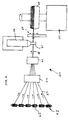
- the apparatus comprises a filament let-off unit 41 holding a plurality of spools 42 of filaments 43. From the let-off unit 41 the filaments 43 pass through a preformer unit 44 in which some or all of the filaments 43 may be preformed and/or twisted as desired. The filaments next pass to a cabling unit 45 in which the filaments are twisted together to form a cord 10. From the cabling unit the cord 10 passes through a cross-head die 47 of a rubber extruder 46 which coats the cord with uncured rubber.
- the rubbered cord then passes over a transversely movable roller 48 which guides the cord onto the outer surface of a rotating tyre carcass 49 mounted on a tyre building machine 50.
- the transversely movable roller 48 is moved slowly to guide the cord to form a spirally wound ply over substantially the whole of the radially outer peripheral parts of the tyre carcass.
- a rubbered cord 10 comprising as shown in Figure 6 a single cord 11 embedded in rubber 12, a plurality of such cords may be formed into a narrow ribbon or tape as shown in Figure 7 for winding onto the tyre carcass.
- the rubbered cord or tape of cords may be formed on the tyre carcass with adjacent windings either overlapping, side-by-side or spaced apart slightly thus providing plies with different cord density.
- the amount of lateral displacement of one or more filaments in the cord may be varied by varying either or both of the preforming or cabling conditions in the respective units 44 and 45. Varying the lateral displacement gradually and continuously makes possible the formation of a ply on the tyre carcass 49 having different extensibilities in different regions laterally across the ply.
- the breaker ply 8 of Figure 1 may be formed by cabling the filaments tightly initially in the cords forming the ply edge region PE and then gradually and continuously cabling them more loosely as the winding progresses towards the axially central part PC of the tyre carcass. Thereafter the filaments of the cord are gradually and continuously cabled more tightly as winding proceeds from the central part PC towards the other edge portion.
- the breaker ply 8 is formed having greater extensibility in the central portion PC than the edge portions PE, with the transition between the two occurring continuously and uniformly across the axial width of the ply.
- variations in lateral displacement may be obtained by varying the degree of preforming of one or more filaments.
- the filaments are preformed by passage around a cylindrical roller.
- one or more filaments 56 are kinked prior to cabling by passage over a polygonal roller.
- the degree of lateral displacement may be varied by varying the number of kinked filaments and/or degree of kinking either by varying the diameter of the polygonal preforming roller or by changing the number of polygonal faces.
- the invention is also not limited to plies formed by spiral or helical wound cords and may by applied to plies having a cord 80,90 or cords wound at acute angles between the ply edges such as shown in Figures 8 and 9.
- the changes in lateral deformation of the filaments have by necessity to be more rapid and more frequent in order to produce a ply having the desired different extensibility in different axial parts.
Landscapes
- Engineering & Computer Science (AREA)
- Mechanical Engineering (AREA)
- Ropes Or Cables (AREA)
- Tires In General (AREA)
- Tyre Moulding (AREA)
Abstract
A reinforcement ply (4) for an elastomeric article comprising a plurality of parallel extensible reinforcing members (7) laid at a substantially constant end count perpendicular to their longitudinal direction, characterised in that the ply (4) has different extensibilities in the longitudinal direction of the reinforcing members (7) in different parts of the ply.
A method of making a reinforcement ply (4) for an elastomeric article comprising a plurality of parallel extensible reinforcing members wherein the ply has different extensibilities in the longitudinal direction of the reinforcing members in different parts of the ply, characterised by displacing a filament (20,30,56) of the reinforcing member perpendicularly from the longitudinal centreline (CCL) of the reinforcing member in at least one part of the reinforcing member compared to another part.
Description
- This invention relates to a reinforcement ply or fabric for elastomeric articles such as hoses, belts, pneumatic actuators, diaphragms or springs, conveyors and tyres or any product which similarly relies on continuous ,reinforcing members for its structural performance. The invention is particularly applicable to the structure and manufacture of breaker and bandage plies which reinforce the ground contacting tread of a tyre.
- The reinforcing plies commonly used in such elastomeric products comprise a plurality of reinforcing members in the form of fibres, filaments or cords laid parallel to each other along the length of the ply and embedded in an elastomeric material such as a rubber compound. In the ply fabric all of the reinforcing members are identical to each other and the use of grooved spacing rollers and an accurately controlled calender ensures that they are equally spaced within a precise thickness of elastomeric matrix. Thus the ply is produced having uniform construction and reinforcing ability across its entire axial width.
- Elastomeric articles in general, and tyres in particular, may suffer from problems associated with changes of shape occurring either in the process of manufacture and/or subsequently in use. These changes in shape can lead to differential strains in the reinforcing plies incorporated therein which can have a detrimental effect on the structural integrity and performance of the product.
- Tyres, for example, are subject to changes in shape during manufacture and subsequently in service. Firstly in the assembly of the 'green' or uncured tyre the reinforced carcass structure is changed from a cylinder to a toroid. Two subsequent changes which affect mainly the tread reinforcing breaker occur firstly when the green tyre is expanded into the mould prior to vulcanisation and secondly when the finished tyre is fitted to the wheelrim and inflated to its working pressure. Both of these change the shape of the initially cylindrical assembly of plies which form the breaker Accordingly differential strains are introduced into the breaker.
- Further changes to the tyre breaker occur under high speed running when the breaker belt edges tend to lift under the influence of centrifugal force. These further differential strains lead to a breakdown of the bond between the steel cords and the rubber matrix leading to so-called 'breaker-edge looseness' which is a common cause of premature tyre failure. Many high speed tyre constructions attempt to mitigate this belt edge lifting problem by wrapping the breaker belt assembly with a further bandage ply of cords arranged parallel to the circumferential direction of the tyre. There have been many proposals for multiple edge windings and/or different materials at the edge of such bandage plies to provide extra reinforcement over the region of the belt edge. All of these proposals however involve use of extra material or an extra manufacturing step which add to the difficulty and expense of manufacture.
- Accordingly there is a clear need in such elastomeric articles for a reinforcing ply which can provide different extensibility and thus different reinforcement in different parts within a single ply such that the ply may accommodate changes in shape without generating extreme differential stresses.
- It is therefore an object of the present invention to provide a reinforcing ply structure, and a method of manufacturing such a ply, which permits a variation in the reinforcing ability in different parts of the ply so that the reinforcement profile can be tailored to the particular product.
- According to one aspect of the present invention a reinforcement ply for an elastomeric article comprises a plurality of parallel extensible reinforcing members laid at a substantially constant end count perpendicular to their longitudinal direction, characterised in that the ply has different extensibilities in the longitudinal direction of the reinforcing members in different parts of the ply.
- The reinforcing members are preferably made from a single cord. By a single cord is meant a base stock cord is used comprising a given construction which is used for all the reinforcing members.
- As will be appreciated in order to get different extensibilities such a single cord needs to have varying material properties and/or varying geometry.
- The reinforcement members preferably comprise at least one filament which is displaced perpendicularly from the longitudinal centreline of the reinforcing member in one part of the reinforcing member compared to another part.
- The displacement of the filament laterally or perpendicular to the longitudinal direction may be in the form of a helix having different helical diameters or different helical pitches in different parts of the ply. The filament may alternatively or additionally be kinked having a different degree of kinking in different parts of the ply.
The filament may be a steel filament. - The elastomeric article may be a tyre and the reinforcing ply may be disposed as a hoop or band in the ground contacting tread region.
- According to another aspect of the invention a method of making a reinforcement ply for an elastomeric article comprising a plurality of parallel extensible reinforcing members wherein the ply has different extensibilities in the longitudinal direction of the reinforcing members in different parts of the ply is characterised by displacing a filament of the reinforcing member perpendicularly from the longitudinal centreline of the reinforcing member in at least one part of the reinforcing member compared to another part.
- By varying the amount or degree of perpendicular or lateral displacement of a filament of the ply member a ply can then be made which has different extensibilities and thus different reinforcing ability in different parts of the ply.
- The change in extensibility may be continuous and progressive across the ply.
- Further aspects of the invention will become apparent from the following description by way of example only of an embodiment of the invention in conjunction with the following drawings in which:
- Figure 1 is a schematic diagram showing a tyre tread region comprising a reinforcing ply according to the present invention;
- Figures 2a-2c are schematic diagrams showing details of the ply member construction in the ply edge area PE of Figure 1;
- Figures 3a-3c are schematic diagrams showing details of the ply member construction in the ply centre area PC of Figure 1;
- Figure 4 is a schematic diagram showing the manufacture of the ply of Figure 1;
- Figure 5 is a schematic diagram of another ply reinforcing member construction according to the invention;
- Figures 6 and 7 are schematic diagrams showing alternative tyre tread reinforcing ply constructions according to the invention; and
- Figures 8 and 9 are schematic diagrams showing a single rubbered reinforcing member and plural reinforcing members rubbered to form a narrow tape.
- Shown in Figure 1 is a cut-away part-section of a moulded pneumatic tyre. The tyre has a
tyre carcass 3 extending between twobead regions 1 and passing through a ground contactingtread region 5. Thetyre carcass 3 is reinforced by carcass ply comprising radially extending rubber covered reinforcing members or cords which are anchored in eachbead region 1 around a circumferentially extending bead hoop or core 6. Eachbead region 1 is further reinforced by afiller ply 2. - In the
tread region 5 the tyre is further reinforced by a belt orbreaker 4. This may comprise one or more reinforcing plies comprising a layer 8 of rubber covered reinforcing members or cords 7 laid parallel to each other. The cords may be inclined with respect to the circumferential direction of the tyre or they may be substantially parallel to the circumferential direction as shown in Figure 1. - According to the present invention the
ply 4 is provided with different reinforcing ability in different regions across its axial width by means of the cords 7 having different extensibilities in the different parts. - As shown in Figures 2 and 3 the cords 7 of the
ply 4 comprises six steel filaments orwires - Figures 2b and 3b show cross-sections of the cords of Figures 2a and 3a in the directions of arrows A-A and B-B respectively. Figures 2c and 3c show details of the displacements de and dc of the
wires - According to the present invention different regions of the
ply 4 are provided with different extensibilities by virtue of variations in the degree or amount of lateral or perpendicular displacement of the filament or filaments of the reinforcing cord. Thus as can be seen from Figures 2 and 3 cords in the ply edge region PE have a smaller helical diameter he than the helical diameter hc of the cords in the ply centre region PC. Accordingly the cords in the ply edge region PE have a smaller filament displacement or deformation de than the filament displacement dc of cords in the ply centre region PC. Accordingly the cords in the ply central region PC are more extensible than the cords in the ply edge region and therefore the ply provides greater reinforcement at the tread edge than in the tread centre. - Alternatively or in addition to having different helical diameters the cords may have different helical pitch or 'lay' lengths PL in different parts of the ply.
- Shown in Figure 4 is a schematic layout of an
apparatus 40 for forming the ply of Figure 1. the apparatus comprises a filament let-offunit 41 holding a plurality ofspools 42 offilaments 43. From the let-offunit 41 thefilaments 43 pass through apreformer unit 44 in which some or all of thefilaments 43 may be preformed and/or twisted as desired. The filaments next pass to acabling unit 45 in which the filaments are twisted together to form acord 10. From the cabling unit thecord 10 passes through across-head die 47 of arubber extruder 46 which coats the cord with uncured rubber. The rubbered cord then passes over a transverselymovable roller 48 which guides the cord onto the outer surface of a rotating tyre carcass 49 mounted on atyre building machine 50. The transverselymovable roller 48 is moved slowly to guide the cord to form a spirally wound ply over substantially the whole of the radially outer peripheral parts of the tyre carcass. - Whilst the above apparatus described the formation of a
rubbered cord 10 comprising as shown in Figure 6 asingle cord 11 embedded inrubber 12, a plurality of such cords may be formed into a narrow ribbon or tape as shown in Figure 7 for winding onto the tyre carcass. - The rubbered cord or tape of cords may be formed on the tyre carcass with adjacent windings either overlapping, side-by-side or spaced apart slightly thus providing plies with different cord density.
- The amount of lateral displacement of one or more filaments in the cord may be varied by varying either or both of the preforming or cabling conditions in the
respective units - For example the breaker ply 8 of Figure 1 may be formed by cabling the filaments tightly initially in the cords forming the ply edge region PE and then gradually and continuously cabling them more loosely as the winding progresses towards the axially central part PC of the tyre carcass. Thereafter the filaments of the cord are gradually and continuously cabled more tightly as winding proceeds from the central part PC towards the other edge portion. In this way the breaker ply 8 is formed having greater extensibility in the central portion PC than the edge portions PE, with the transition between the two occurring continuously and uniformly across the axial width of the ply.
- Alternatively or additionally variations in lateral displacement may be obtained by varying the degree of preforming of one or more filaments. Commonly in forming the helically wound cords of Figures 2 and 3 the filaments are preformed by passage around a cylindrical roller. In the alternative
ply reinforcing cord 55 shown in Figure 5, one ormore filaments 56 are kinked prior to cabling by passage over a polygonal roller. In such a cord the degree of lateral displacement may be varied by varying the number of kinked filaments and/or degree of kinking either by varying the diameter of the polygonal preforming roller or by changing the number of polygonal faces. - The invention is also not limited to plies formed by spiral or helical wound cords and may by applied to plies having a
cord
Claims (28)
- A reinforcement ply (4) for an elastomeric article comprising a plurality of parallel extensible reinforcing members (7) laid at a substantially constant end count perpendicular to their longitudinal direction, characterised in that the ply (4) has different extensibilities in the longitudinal direction of the reinforcing members (7) in different parts of the ply.
- A reinforcement ply according to claim 1, characterised in that reinforcing members (7) are made from a single cord.
- A reinforcement ply according to claim 1 or 2, characterised in that the reinforcing members (7) comprises at least one filament (20,30,56) which is displaced perpendicularly from the longitudinal centreline (CCL) of the reinforcing member in at least one part of the reinforcing member compared to another part.
- A reinforcement ply according to any of claims 1 to 3, characterised in that the extensibility changes progressively and continuously across the ply (4).
- A reinforcement ply according to claim 3 or 4, characterised in that the filament (20,30) is displaced in a helix having different helical diameters (he,hc) in different parts of the ply.
- A reinforcement ply according to any of claims 3 to 5, characterised in that the filament (20,30) is deformed in a helix having different helical pitches (PL) or 'lay lengths' in different parts of the ply.
- A reinforcement ply according to any of claims 3 to 6, characterised in that the filament (56) is kinked.
- A reinforcement ply according to any of claims 3 to 7, characterised in that the filament is steel.
- A reinforcement ply according to any of claims 1 to 8, characterised in that the elastomeric article is a tyre.
- A reinforcement ply according to claim 9, characterised in that the reinforcement ply (4) is disposed in the ground contacting tread region of the tyre in the form of a hoop or band.
- A reinforcement ply according to claim 10, characterised in that the reinforcing members are substantially parallel to the circumferential direction of the tyre.
- A reinforcement ply according to claim 11, characterised in that the reinforcement ply comprises a helical winding of the reinforcing member or members.
- A reinforcing ply according to claim 12, characterised in that the reinforcing ply (4) comprises a continuous helical winding across the axial width of the ply.
- A reinforcing ply according to claim 10, characterised in that the reinforcing members are disposed at an acute angle to the tyre circumferential direction.
- A reinforcing ply according to claim 14, characterised in that the reinforcing members are disposed zigzag between the axial edges of the reinforcing ply.
- A reinforcing ply according to any of claims 10 to 15, characterised in that the filaments of the reinforcing members in the central region (PC) of the band are laterally deformed to a greater extent than the filaments of the members in the edge regions (PE) of the band such that the reinforcing ply has greater extensibility in the central region of the tread than in the axially outer regions nearest to the tread shoulders.
- A method of making a reinforcement ply (4) for an elastomeric article comprising a plurality of parallel extensible reinforcing members wherein the ply has different extensibilities in the longitudinal direction of the reinforcing members in different parts of the ply, characterised by displacing a filament (20,30,56) of the reinforcing member perpendicularly from the longitudinal centreline (CCL) of the reinforcing member in at least one part of the reinforcing member compared to another part.
- A method of making a reinforcement ply according to claim 17, characterised by varying the helical diameter (he,hd) of a helically displaced filament.
- A method of making a reinforcement ply according to either of claims 17 or 18, characterised by varying the helical pitch (PL) or 'lay length' of a helically displaced filament.
- A method of making a reinforcement ply according to claim 17, characterised by varying the degree of kinking of a kinked filament (56).
- A method of making a reinforcement ply for the ground contacting tread region of a tyre according to any of claims 17 to 20, characterised by the continuous sequence of laterally deforming at least one filament, forming the reinforcing member comprising said at least one deformed filament and forming said reinforcement ply as a band or hoop.
- A method of making a reinforcing ply for a tyre tread according to claim 21, characterised in that between forming the reinforcing member and forming the band or hoop the reinforcing member is coated with a vulcanisable rubber material.
- A method of making a reinforcing ply for a tyre according to claim 22, characterised in that several reinforcing members (h) are brought into close linear proximity and coated with a vulcanisable rubber (12) material to form a narrow tape (10).
- A method of making a reinforcing ply for a tyre tread according to either of claims 22 or 23, characterised by forming the band by laying the reinforcing members (80,90) zigzag between the edges of the band.
- A method of making a reinforcing ply for a tyre tread according to either of claims 22 or 23, characterised by forming the band by helically winding the reinforcing member at substantially zero degrees to the band circumferential direction.
- A method of making a reinforcing ply for a tyre tread according to claim 25, characterised by forming the band from a single continuous helical winding.
- A method of making a reinforcing ply for a tyre tread according to any of claims 21 to 26, characterised by laterally displacing the filaments of the reinforcing members forming the centre part (PC) of the band more than those of the members forming the edge parts (PE) of the band.
- A method according to claim 26, characterised by continuously increasing the displacement in the filaments of the reinforcing member in winding the band from one band edge towards the band centre and decreasing the displacement in winding from the band centre to the other band edge.
Applications Claiming Priority (2)
| Application Number | Priority Date | Filing Date | Title |
|---|---|---|---|
| GBGB9603948.2A GB9603948D0 (en) | 1996-02-24 | 1996-02-24 | Reinforcement ply and method of manufacture |
| GB9603948 | 1996-02-24 |
Publications (1)
| Publication Number | Publication Date |
|---|---|
| EP0791485A1 true EP0791485A1 (en) | 1997-08-27 |
Family
ID=10789349
Family Applications (1)
| Application Number | Title | Priority Date | Filing Date |
|---|---|---|---|
| EP97301188A Withdrawn EP0791485A1 (en) | 1996-02-24 | 1997-02-24 | Reinforcement ply and method of manufacture |
Country Status (4)
| Country | Link |
|---|---|
| US (1) | US6089293A (en) |
| EP (1) | EP0791485A1 (en) |
| JP (1) | JPH09323504A (en) |
| GB (1) | GB9603948D0 (en) |
Cited By (4)
| Publication number | Priority date | Publication date | Assignee | Title |
|---|---|---|---|---|
| EP0978396A3 (en) * | 1998-08-03 | 2001-08-16 | Continental Aktiengesellschaft | Vehicle tyre |
| US6321809B1 (en) * | 1999-12-22 | 2001-11-27 | The Goodyear Tire & Rubber Company | Unique radial passenger tire construction for RAT/RLF |
| WO2004018237A1 (en) | 2002-08-09 | 2004-03-04 | Societe De Technologie Michelin | Tyre for two-wheeled vehicles |
| WO2003101714A3 (en) * | 2002-06-03 | 2004-09-23 | Michelin Soc Tech | System for producing a reinforcing structure for a tyre with volumetric control of the die |
Families Citing this family (17)
| Publication number | Priority date | Publication date | Assignee | Title |
|---|---|---|---|---|
| JP2001253374A (en) | 2000-03-08 | 2001-09-18 | Ohtsu Tire & Rubber Co Ltd :The | Wrap around endless tension belt, its molding method, rubber composition for covering tensile strength cord, and elastic endless rotating belt |
| JP4392139B2 (en) * | 2001-05-09 | 2009-12-24 | 住友ゴム工業株式会社 | Metal cord and pneumatic tire using the same |
| US6748731B2 (en) * | 2002-04-08 | 2004-06-15 | Tokusen U.S.A., Inc. | Tire cord |
| US7404425B2 (en) * | 2002-04-24 | 2008-07-29 | The Goodyear Tire & Rubber Company | Belt package for super single truck tires |
| US7658216B2 (en) * | 2002-08-09 | 2010-02-09 | Michelin Recherche Et Technique S.A. | Tire for two-wheeled vehicle comprising looped crown reinforcement |
| US20050048280A1 (en) * | 2003-08-29 | 2005-03-03 | Stamper Rodney Gene | Apparatus and process for making a tape useful as a tire cap ply |
| PL1841605T3 (en) * | 2005-01-25 | 2009-04-30 | Pirelli | Pneumatic tyre with improved bead structure |
| FR2897557B1 (en) * | 2006-02-21 | 2008-04-18 | Michelin Soc Tech | PNEUMATIC FOR VEHICLES |
| JP4866123B2 (en) * | 2006-03-27 | 2012-02-01 | 横浜ゴム株式会社 | Pneumatic tire manufacturing method |
| FR2916160B1 (en) * | 2007-05-14 | 2009-07-17 | Michelin Soc Tech | PNEUMATIC FOR HEAVY VEHICLES |
| DE102007044153A1 (en) * | 2007-09-15 | 2009-03-26 | Continental Aktiengesellschaft | Reinforcing layer of hybrid cords for elastomeric products |
| CN102369321B (en) * | 2009-04-03 | 2014-08-13 | 贝卡尔特公司 | High elongation steel cord with preformed strands |
| CN108699789B (en) * | 2016-02-23 | 2021-02-23 | 贝卡尔特公司 | Energy absorbing assembly |
| WO2017156737A1 (en) * | 2016-03-17 | 2017-09-21 | Nv Bekaert Sa | A m+n steel cord for reinforcing rubber product |
| US11760128B2 (en) * | 2018-07-25 | 2023-09-19 | Compagnie Generale Des Etablissements Michelin | Highly compressible open cord |
| JP7223257B2 (en) * | 2018-12-27 | 2023-02-16 | 住友ゴム工業株式会社 | Band-shaped rubber material manufacturing apparatus and manufacturing method |
| CN115404709B (en) * | 2022-08-31 | 2023-05-30 | 江苏兴达钢帘线股份有限公司 | Steel cord, production method thereof and tire |
Citations (6)
| Publication number | Priority date | Publication date | Assignee | Title |
|---|---|---|---|---|
| FR2056478A5 (en) * | 1970-03-20 | 1971-05-14 | Furstenwalde Reifenkombi | Steel reinforced rubber articles prodn |
| US4045990A (en) * | 1974-01-10 | 1977-09-06 | Milliken Research Corporation | Endless reinforcement |
| GB2009270A (en) * | 1977-10-28 | 1979-06-13 | Bridgestone Tire Co Ltd | Rubber reinforcing member and a method of manufacturing the same |
| US5135039A (en) * | 1989-07-31 | 1992-08-04 | Kokoku Steel Wire Ltd. | Tire including steel tire cords |
| DE4209818A1 (en) * | 1992-03-26 | 1993-09-30 | Uniroyal Englebert Gmbh | Radial pneumatic tyre - has cover fabric over running belt layer wound at high tension near shoulders and in wavy pattern near middle |
| DE4334650C1 (en) * | 1993-10-12 | 1995-03-02 | Uniroyal Englebert Gmbh | Pneumatic vehicle tires with radial carcass |
Family Cites Families (15)
| Publication number | Priority date | Publication date | Assignee | Title |
|---|---|---|---|---|
| JPS5643008A (en) * | 1979-09-13 | 1981-04-21 | Bridgestone Corp | Pneumatic radial tire |
| FR2473080A1 (en) * | 1979-12-21 | 1981-07-10 | Kanai Hiroyuki | STEEL CABLE |
| DE3855332T2 (en) * | 1987-06-18 | 1996-10-02 | Sumitomo Rubber Ind | Belted tires and manufacturing method |
| FR2623786B1 (en) * | 1987-11-30 | 1990-03-23 | Michelin & Cie | DEVICE AND METHOD FOR APPLYING WIRES ON A SUPPORT IN PARTICULAR IN A SINUOUS FORM |
| US5271445A (en) * | 1988-09-19 | 1993-12-21 | Bridgestone Corporation | Pneumatic tire including wave-shaped cords or filaments |
| JP2646390B2 (en) * | 1989-02-27 | 1997-08-27 | 横浜ゴム株式会社 | Pneumatic radial tire |
| AU625337B2 (en) * | 1989-05-31 | 1992-07-09 | Sp Reifenwerke Gmbh | Vehicle tyre |
| US5213652A (en) * | 1989-09-11 | 1993-05-25 | The Yokohama Rubber Co., Ltd. | Pneumatic radial tire including 1×2 steel cords |
| JP2788655B2 (en) * | 1989-10-13 | 1998-08-20 | 住友ゴム工業 株式会社 | Motorcycle tires |
| JPH03176205A (en) * | 1989-12-01 | 1991-07-31 | Bridgestone Corp | Radial tire containing air |
| EP0433962B1 (en) * | 1989-12-20 | 1998-05-06 | Tokusen Kogyo Company Limited | Steel cord for reinforcement of rubber products |
| JPH04281081A (en) * | 1991-03-06 | 1992-10-06 | Bridgestone Corp | Metallic cord for reinforcing rubber and tire using the same |
| JP2672749B2 (en) * | 1991-08-06 | 1997-11-05 | 住友電気工業株式会社 | Metal cord and composite of this and rubber |
| JPH06255310A (en) * | 1993-03-08 | 1994-09-13 | Sumitomo Rubber Ind Ltd | Radial tire for motorcycle |
| US5975417A (en) * | 1997-12-19 | 1999-11-02 | Ncr Corporation | Convertible barcode scanner |
-
1996
- 1996-02-24 GB GBGB9603948.2A patent/GB9603948D0/en active Pending
-
1997
- 1997-02-10 JP JP9026859A patent/JPH09323504A/en active Pending
- 1997-02-24 US US08/804,754 patent/US6089293A/en not_active Expired - Lifetime
- 1997-02-24 EP EP97301188A patent/EP0791485A1/en not_active Withdrawn
Patent Citations (6)
| Publication number | Priority date | Publication date | Assignee | Title |
|---|---|---|---|---|
| FR2056478A5 (en) * | 1970-03-20 | 1971-05-14 | Furstenwalde Reifenkombi | Steel reinforced rubber articles prodn |
| US4045990A (en) * | 1974-01-10 | 1977-09-06 | Milliken Research Corporation | Endless reinforcement |
| GB2009270A (en) * | 1977-10-28 | 1979-06-13 | Bridgestone Tire Co Ltd | Rubber reinforcing member and a method of manufacturing the same |
| US5135039A (en) * | 1989-07-31 | 1992-08-04 | Kokoku Steel Wire Ltd. | Tire including steel tire cords |
| DE4209818A1 (en) * | 1992-03-26 | 1993-09-30 | Uniroyal Englebert Gmbh | Radial pneumatic tyre - has cover fabric over running belt layer wound at high tension near shoulders and in wavy pattern near middle |
| DE4334650C1 (en) * | 1993-10-12 | 1995-03-02 | Uniroyal Englebert Gmbh | Pneumatic vehicle tires with radial carcass |
Cited By (5)
| Publication number | Priority date | Publication date | Assignee | Title |
|---|---|---|---|---|
| EP0978396A3 (en) * | 1998-08-03 | 2001-08-16 | Continental Aktiengesellschaft | Vehicle tyre |
| US6321809B1 (en) * | 1999-12-22 | 2001-11-27 | The Goodyear Tire & Rubber Company | Unique radial passenger tire construction for RAT/RLF |
| WO2003101714A3 (en) * | 2002-06-03 | 2004-09-23 | Michelin Soc Tech | System for producing a reinforcing structure for a tyre with volumetric control of the die |
| US7399374B2 (en) | 2002-06-03 | 2008-07-15 | Michelin Recherche Et Technique S.A. | System for producing a reinforcing structure for a tire with volumetric control |
| WO2004018237A1 (en) | 2002-08-09 | 2004-03-04 | Societe De Technologie Michelin | Tyre for two-wheeled vehicles |
Also Published As
| Publication number | Publication date |
|---|---|
| JPH09323504A (en) | 1997-12-16 |
| GB9603948D0 (en) | 1996-04-24 |
| US6089293A (en) | 2000-07-18 |
Similar Documents
| Publication | Publication Date | Title |
|---|---|---|
| US6089293A (en) | Tire containing reinforcement ply with parallel extensible reinforcing members and method of manufacture | |
| RU2213008C2 (en) | Method of manufacture of vehicle wheel tires (versions) | |
| EP0319588B1 (en) | Pneumatic radial tire and production thereof | |
| EP0928702B1 (en) | A tyre for vehicle wheels | |
| EP0928680B1 (en) | A method for making tyres for vehicle wheels | |
| US3729365A (en) | Endless reinforcement and method for producing same | |
| EP0148099B1 (en) | A reinforced hose and a method of manufacture | |
| JP3216819B2 (en) | Method of manufacturing tire for motorcycle and tire thereof | |
| RU2223868C2 (en) | Vehicle tire (versions) | |
| US8211258B2 (en) | Method and device for producing a tread for a vehicle tire | |
| US20020189737A1 (en) | Method for manufacturing a tyre | |
| US5935354A (en) | Tire having reinforcement ply with discontinuous substantially circumferential metal wires or cables | |
| KR20010094733A (en) | Method And Device For Manufacturing A Metal Cord For Reinforcing Elastomeric Products, Particularly Tyres | |
| CN1160790A (en) | Reinforcing metallic cord process and apparatus for manufacture of same and reinforced pneumatic tyres provided with said cord | |
| CN1827352A (en) | Apparatus and method of manufacturing undulated webs | |
| US7094302B2 (en) | Method of forming a belt structure in a tire, in particular for motorcycle wheels | |
| CN1803447A (en) | Apparatus for making tire components, and a tire | |
| CZ20012278A3 (en) | Process and apparatus for producing metallic core intended for reinforcement of elastomer products, particularly pneumatic tyres | |
| EP1691970B1 (en) | A process and apparatus for producing a semifinished product for manufacturing tyres for vehicle wheels | |
| KR101141032B1 (en) | Reinforcement material for rubber, rubber product using the material and method for producing the product, pneumatic tire using the material and method for producing the tire | |
| US6354349B1 (en) | Seamless reinforcement for rubber composition and products incorporating such material | |
| EP1011962A1 (en) | Seamless reinforcement for rubber composition and products incorporating such material | |
| EP1372987B1 (en) | Method of forming a belt structure in a tyre, in particular for motorcycle wheels | |
| JP2001055676A (en) | Steel cord for reinforcing rubber material, its production and pneumatic tire | |
| CA1121706A (en) | Method and apparatus for manufacturing a pneumatic tire |
Legal Events
| Date | Code | Title | Description |
|---|---|---|---|
| PUAI | Public reference made under article 153(3) epc to a published international application that has entered the european phase |
Free format text: ORIGINAL CODE: 0009012 |
|
| AK | Designated contracting states |
Kind code of ref document: A1 Designated state(s): DE FR GB |
|
| 17P | Request for examination filed |
Effective date: 19980212 |
|
| 17Q | First examination report despatched |
Effective date: 19991115 |
|
| STAA | Information on the status of an ep patent application or granted ep patent |
Free format text: STATUS: THE APPLICATION IS DEEMED TO BE WITHDRAWN |
|
| 18D | Application deemed to be withdrawn |
Effective date: 20000921 |