EP0791435A1 - Motor-driven handtool - Google Patents
Motor-driven handtool Download PDFInfo
- Publication number
- EP0791435A1 EP0791435A1 EP96119429A EP96119429A EP0791435A1 EP 0791435 A1 EP0791435 A1 EP 0791435A1 EP 96119429 A EP96119429 A EP 96119429A EP 96119429 A EP96119429 A EP 96119429A EP 0791435 A1 EP0791435 A1 EP 0791435A1
- Authority
- EP
- European Patent Office
- Prior art keywords
- handle
- hand tool
- tool according
- fastening element
- opening
- Prior art date
- Legal status (The legal status is an assumption and is not a legal conclusion. Google has not performed a legal analysis and makes no representation as to the accuracy of the status listed.)
- Granted
Links
Images

Classifications
-
- B—PERFORMING OPERATIONS; TRANSPORTING
- B25—HAND TOOLS; PORTABLE POWER-DRIVEN TOOLS; MANIPULATORS
- B25F—COMBINATION OR MULTI-PURPOSE TOOLS NOT OTHERWISE PROVIDED FOR; DETAILS OR COMPONENTS OF PORTABLE POWER-DRIVEN TOOLS NOT PARTICULARLY RELATED TO THE OPERATIONS PERFORMED AND NOT OTHERWISE PROVIDED FOR
- B25F5/00—Details or components of portable power-driven tools not particularly related to the operations performed and not otherwise provided for
- B25F5/02—Construction of casings, bodies or handles
- B25F5/025—Construction of casings, bodies or handles with torque reaction bars for rotary tools
- B25F5/026—Construction of casings, bodies or handles with torque reaction bars for rotary tools in the form of an auxiliary handle
-
- B—PERFORMING OPERATIONS; TRANSPORTING
- B24—GRINDING; POLISHING
- B24B—MACHINES, DEVICES, OR PROCESSES FOR GRINDING OR POLISHING; DRESSING OR CONDITIONING OF ABRADING SURFACES; FEEDING OF GRINDING, POLISHING, OR LAPPING AGENTS
- B24B23/00—Portable grinding machines, e.g. hand-guided; Accessories therefor
- B24B23/005—Auxiliary devices used in connection with portable grinding machines, e.g. holders
Landscapes
- Engineering & Computer Science (AREA)
- Mechanical Engineering (AREA)
- Finish Polishing, Edge Sharpening, And Grinding By Specific Grinding Devices (AREA)
Abstract
Description
Die Erfindung betrifft ein motorbetriebenes Handwerkzeug, wie z.B. einen Exzenter-, Winkel- oder Schwingschleifer oder Sander, mit einem abnehmbaren Handgriff.The invention relates to a motor-operated hand tool, e.g. an eccentric, angle or orbital sander or sander, with a removable handle.
Es kann sich hierbei um Elektrohandwerkzeuge oder aber um kompressorbetriebene Handwerkzeuge handeln. Bekannte Handwerkzeuge sind häufig mit zwei Handgriffen ausgestattet, wobei einer oftmals als abnehmbarer Zusatzhandgriff ausgebildet ist. So sind Handbohrmaschinen bekannt, bei denen ein länglicher, gerader Handgriff mit einem vorstehenden Gewindeabschnitt quer zur Richtung der Bohrspindel in eine Öffnung des Maschinengehäuses einschraubbar ist. Hierbei muß der Handgriff mehrmals um sich selbst gedreht werden, was ein mehrfaches Umgreifen erfordert und umständlich ist. Bei einer anderen bekannten Bohrmaschine wird der ebenfalls quer zur Bohrspindel verlaufende Handgriff über eine schellenartige Befestigung, die über den Bohrfutterbereich der Bohrmaschine gestülpt wird, am Werkzeuggehäuse montiert, wobei eine Flügelmutter manuell gespannt bzw. gelöst wird. Die Montage bzw. Demontage dieses Handgriffs ist extrem aufwendig, da die Bohrmaschine entweder zwischen Oberarm und Körper oder zwischen den Beinen gehalten wird, während eine Hand den Handgriff in die erwünschte Position relativ zum Maschinengehäuse bringt und die andere Hand zum Spannen der erwähnten Flügelmutter benötigt wird.These can be electrical hand tools or compressor-operated hand tools. Known hand tools are often equipped with two handles, one of which is often designed as a removable additional handle. So hand drills are known in which an elongated, straight handle with a protruding threaded portion transverse to the direction of Drill spindle can be screwed into an opening in the machine housing. Here, the handle must be turned several times around itself, which requires multiple gripping and is cumbersome. In another known drilling machine, the handle, which also runs transversely to the drilling spindle, is mounted on the tool housing by means of a clamp-like fastening which is placed over the drill chuck area of the drilling machine, a wing nut being manually tensioned or loosened. The assembly or disassembly of this handle is extremely complex, since the drill is held either between the upper arm and body or between the legs, while one hand brings the handle into the desired position relative to the machine housing and the other hand is required to tighten the wing nut mentioned .
Aus der DE 42 03 171 C1 ist ein Schleifgerät der gattungsgemäßen Art bekannt, dessen abnehmbarer Zusatzhandgriff in Umfangsrichtung bzgl. der Werkzeugantriebsachse außen am Maschinengehäuse verfahrbar ist. Der Handgriff besteht im wesentlichen aus einem kugelförmigen Knopf mit einem Innengewinde, das mit einem Gewindebolzen verschraubbar ist, der aus einer in Umfangsrichtung verfahrbaren sphärisch gewölbten Aufnahme heausragt. Zum Aufschrauben des Knopfs muß dieser mehrfach gedreht werden, und ein aufwendiges Umgreifen ist erforderlich. Eine ergonomische Formgebung des Handgriffs ist nicht möglich, sondern seine rotationssymmetrische Ausgestaltung ist vielmehr vorgegeben.From DE 42 03 171 C1 a grinding device of the generic type is known, the removable additional handle of which can be moved in the circumferential direction with respect to the tool drive axis on the outside of the machine housing. The handle essentially consists of a spherical button with an internal thread that can be screwed with a threaded bolt that protrudes from a spherically curved receptacle that can be moved in the circumferential direction. To unscrew the button, it has to be turned several times, and it is difficult to reach around required. Ergonomic shaping of the handle is not possible, but rather its rotationally symmetrical design is predetermined.
Der Erfindung liegt daher die Aufgabe zugrunde, ein Handwerkzeug der gattungsgemäßen Art dahingehend zu verbessern, daß der Handgriff auf einfachere Art montierbar bzw. abnehmbar ist und dabei eine für das betreffende Arbeitsgerät günstige ergonomische Formgebung zuläßt. Beim Montieren bzw. Abnehmen des Handgriffs soll das Handwerkzeug sowie der Handgriff einfach handhabbar sein; ein mehrfaches Umgreifen soll nicht erforderlich sein, und es dürfen auch keine Probleme beim Halten oder Abstützen des Handwerkzeugs auftreten.The invention is therefore based on the object of improving a hand tool of the generic type in such a way that the handle can be assembled or removed in a simpler manner and thereby permits an ergonomic shape which is favorable for the implement in question. When mounting or removing the handle, the hand tool and the handle should be easy to handle; repeated gripping should not be necessary, and there should also be no problems with holding or supporting the hand tool.
Diese Aufgabe wird bei einem motorbetriebenen Handwerkzeug erfindungsgemäß dadurch gelöst, daß der Handgriff ein im Handhabungsbereich des Handgriffs angeordnetes und zum manuellen Motieren bzw. Abnehmen des Handgriffs gegenüber diesem bewegbares, insbesondere drehbares Befestigungselement aufweist.This object is achieved with a motor-driven hand tool according to the invention characterized in that the handle is a arranged in the handling region of the handle and manually Motieren or removal of the handle having opposite this movable, in particular rotatable fastener.
Dadurch, daß das Befestigungselement im Handhabungsbereich des Handgriffs vorgesehen ist und gegenüber diesem zum Montieren bzw. Lösen bewegbar, insbesondere drehbar ist, ist ein mehrfaches Umgreifen, wie es eingangs als nachteilig geschildert wurde, entbehrlich; der Handgriff wird mit einer Hand gehalten bzw. positioniert und es wird mit derselben Hand das Befestigungselement zum Befestigen bzw. Lösen des Handgriffs betätigt, insbesondere mit den Fingern gedreht, während der Handgriff mit der hohlen Hand weiter gehalten wird bzw. in der hohlen Hand verbleibt und dabei gestützt wird.The fact that the fastening element is provided in the handling area of the handle and can be moved, in particular rotated, relative to the handle for mounting or releasing, means that it can be gripped several times, as initially mentioned was described disadvantageously, dispensable; the handle is held or positioned with one hand and the fastening element for fastening or loosening the handle is actuated with the same hand, in particular rotated with the fingers, while the handle is held further with the hollow hand or remains in the hollow hand while being supported.
Bei einer vorteilhaften Ausführungsform der Erfindung handelt es sich bei dem Befestigungselement um eine im Handgriff lanegesicherte Schraube mit einem manuell greifbaren und betätigbaren Kopf. Der Schraubenkopf wird hierfür vorzugsweise mit dem Daumen und Zeigefinger oder Mittelfinger gegriffen und gedreht. Es sind jedoch auch andere Befestigungselemente, wie z.B. in Form eines Bajonettverschlußes, denkbar. Selbst wenn es sich um ein drehbares Befestigungselement handelt, muß dieses nicht notwendigerweise von einer Schraube gebildet sein, sondern es könnte sich auch um ein mit einem Betätigungskopf verbindbares Gewindeteil handeln, das mit einem von dem Werkzeuggehäuse vorstehenden Gewindebolzen verschraubbar ist. Anstelle einer Schraube könnte auch ein begrenzt verschieblicher Stift mit im Werkzeugkörper verrastbaren Ringnuten oder ein einsteckbarer und durch Drehung sicherbarer, einen Anschlag hintergreifender oder verrastbarer Stift verwendet werden.In an advantageous embodiment of the invention, the fastening element is a screw secured in length in the handle with a manually graspable and actuatable head. For this purpose, the screw head is preferably gripped and rotated with the thumb and index finger or middle finger. However, other fastening elements, such as in the form of a bayonet lock, are also conceivable. Even if it is a rotatable fastening element, it does not necessarily have to be formed by a screw, but it could also be a threaded part which can be connected to an actuating head and which can be screwed to a threaded bolt projecting from the tool housing. Instead of a screw, it would also be possible to use a pin which can be displaced to a limited extent with ring grooves which can be locked in the tool body, or a pin which can be inserted and secured by rotation and engages behind or locks a stop.
Bei einer ganz besonders vorteilhaften Ausführungsform der Erfindung weist der Handgriff eine in der Grifffläche mündende Ausnehmung auf, in der das Befestigungselement manuell betätigbar vorgesehen ist. In Weiterbildung dieses Erfindungsgedankens steht das Befestigungselement aus der Ausnehmung über die Grifffläche vor und ist damit greifbar, insbesondere drehbar. Bei dieser bevorzugten Ausführungsform braucht die Ausnehmung nicht derart groß bemessen zu werden, daß ein Benutzer des Handgeräts mit den Fingern in die Ausnehmung hinein zu dem Befestigungselement gelangen kann, sondern die Ausnehmung kann im wesentlichen der Form des Befestigungselements angepaßt sein und dieses recht eng umgeben. Hierdurch wird auch in optischer Hinsicht ein kompaktes ansprechendes Erscheinungsbild des Handgriffs erreicht. Der Handgriff kann bspw. die Form eines ergonomisch geformten Knaufs aufweisen und die Ausnehmung kann als Durchbruch von einer Seite der Grifffläche des Knaufs zur anderen Seite erstreckt sein. Das Befestigungselement steht dann vorzugsweise auf den zwei gegenüberliegenden Seiten des Handgriffs über die Grifffläche vor.In a very particularly advantageous embodiment of the invention, the handle has a recess which opens into the grip surface and in which the fastening element can be actuated manually. In a further development of this inventive concept, the fastening element protrudes from the recess over the gripping surface and can thus be gripped, in particular rotated. In this preferred embodiment, the recess need not be dimensioned so large that a user of the hand-held device can use his fingers to get into the recess to the fastening element, but the recess can be essentially adapted to the shape of the fastening element and surround it quite closely. In this way, a compact, attractive appearance of the handle is also achieved from an optical point of view. The handle can have the shape of an ergonomically shaped knob, for example, and the recess can extend as an opening from one side of the grip surface of the knob to the other side. The fastening element then preferably projects over the grip surface on the two opposite sides of the handle.
Die Position des Handgriffs am Werkzeugkörper ist vorzugsweise vorgegeben. Dabei erweist es sich als vorteilhaft, wenn der Handgriff gegenüber dem Werkzeugkörper nicht unbeabsichtigt verdrehbar oder verschwenkbar ist; dies kann vorzugsweise durch eine komplementäre Formgebung von Werkzeugkörper und Handgriff erreicht werden, indem bspw. der Krümmungsradius der an den Werkzeugkörper anlegbaren Seite des Handgriffs entsprechend der Krümmung des Werkzeugkörpers ausgebildet ist. Zusätzlich können zwischen Handgriff und Werkzeugkörper Rippen, Stege, Stifte und entsprechend ausgebildete Ausnehmungen in dem anderen Teil vorgesehen sein.The position of the handle on the tool body is preferably predetermined. It proves to be advantageous if the handle cannot be unintentionally rotated or rotated relative to the tool body is pivotable; this can preferably be achieved by a complementary shaping of the tool body and handle, for example by the radius of curvature of the side of the handle which can be placed on the tool body being designed in accordance with the curvature of the tool body. In addition, ribs, webs, pins and correspondingly formed recesses can be provided in the other part between the handle and the tool body.
Der Handgriff umfaßt vorteilhafterweise zwei Halbschalenteile, die auf einfache Art und Weise bspw. im Spritzgußverfahren aus Kunststoff herstellbar und vorzugsweise miteinander verrastbar sind.The handle advantageously comprises two half-shell parts which can be produced in a simple manner, for example by injection molding, from plastic and can preferably be locked together.
Die Halbschalenteile begrenzen vorteilhafterweise eine Durchgangsöffnung für das Befestigungselement, welches vor dem Schließen der Halbschalenteile in die eine Öffnungshälfte eingesetzt und durch Verbindung der Halbschalenteile innerhalb der Öffnung lagegesichert wird.The half-shell parts advantageously delimit a through opening for the fastening element, which is inserted into the one opening half before the half-shell parts are closed and is secured in position within the opening by connecting the half-shell parts.
Bei einer bevorzugten Ausführungsform der Erfindung weist das ansich manuell betätigbare Befestigungselement zusätzlich eine Werkzeugansetzstelle, z.B. für einen Schraubenzieher, einen Inbus oder dgl., auf. Dies kann sich dann als vorteilhaft erweisen, wenn eine dauerhafte Montage des Handgriffs an dem Werkzeugkörper erwünscht und daher eine manuell unlösbare Montage vorteilhaft wäre. Aber auch für den Fall, daß der Handgriff abgenommen werden soll und der Benutzer das Befestigungselement nicht manuell zu lösen vermag, erweist sich diese Ausführungsform als zweckmäßig und vorteilhaft. Wenn das Befestigungselement in einer Ausnehmung im Handgriff untergebracht ist, kann dieser eine in der Ausnehmung mündende Zugangsöffnung zu der Werkzeugansetzstelle des Befestigungselements aufweisen.In a preferred embodiment of the invention, the fastening element, which can itself be operated manually, additionally has a tool attachment point, for example for a screwdriver, an Allen key or the like. This can prove to be advantageous if permanent assembly of the handle on the tool body is desired and therefore a manually unsolvable assembly would be advantageous. But also in the event that the handle is to be removed and the user is not able to loosen the fastening element manually, this embodiment proves to be expedient and advantageous. If the fastening element is accommodated in a recess in the handle, this can have an access opening which opens into the recess to the tool attachment point of the fastening element.
Weitere Merkmale, Einzelheiten und Vorteile der Erfindung ergeben sich aus den beigefügten Patentansprüchen und der zeichnerischen Darstellung sowie der nachfolgenden Beschreibung einer vorteilhaften Ausführungsform der Erfindung. In der Zeichnung zeigt:
- Figur 1
- eine Seitenansicht eines erfindungsgemäß ausgebildeten Handwerkzeugs;
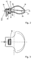
- Figur 2
- einen Schnitt durch einen abnehmbaren Handgriff des Handwerkzeugs nach Figur 1 und
- Figur 3
- eine Draufsicht auf den Handgriff nach Figur 2.
- Figure 1
- a side view of a hand tool designed according to the invention;
- Figure 2
- a section through a removable handle of the hand tool according to Figure 1 and
- Figure 3
- a plan view of the handle of Figure 2.
Figur 1 zeigt einen insgesamt mit dem Bezugszeichen 2 bezeichneten handgeführten Exzenterschleifer mit einem ersten gehäusefesten Handgriff 4, der eine Durchgriffsöffnung 6 begrenzt. In diese Durchgriffsöffnung 6 erstreckt sich vom Handgriff 4 aus eine Betätigungstaste 8. Der Handgriff 4 ist an einem Motorengehäuse 10 angeformt, in welchem Entlüftungsschlitze 12 ausgebildet sind, das aber in seinem oberen Bereich auch zum Handhaben und Führen des Exzenterschleifers mit der Hand gegriffen werden kann. Um den Exzenterschleifer 2 noch besser führen zu können, ist ein zusätzlicher abnehmbarer Handgriff 14 in der Nähe des exzentrisch angetriebenen Schleifkopfs im unteren Bereich des Werkzeugkörpers vorgesehen. Der Handgriff 14 hat eine ergonomisch gewölbte Knaufform 16 und ist in der Draufsicht (Figur 3) T-förmig, ohne jedoch Ecken oder Kanten aufzuweisen. Der Handgriff 14 umfaßt zwei Halbschalenteile 18, 20 aus einem Kunststoffmaterial, die miteinander verrastbar sind. Der Handgriff 14 ist mittels eines gegenüber den Halbschalenteilen 18, 20 drehbaren Befestigungselements 22 in Form einer Schraube 24 am Werkzeugkörper befestigbar.FIG. 1 shows a hand-held eccentric sander, designated overall by reference number 2, with a first handle 4 fixed to the housing, which delimits a passage opening 6. In this through
Beide Halbschalenteile 18, 20 weisen in ihrer Grifffläche 26, 28 einen Durchbruch 30, 32 bzw. eine Durchgangsöffnung auf, wodurch innerhalb des Handgriffs 14 eine Ausnehmung 34 für die Aufnahme und Lagesicherung der Schraube 24 begrenzt bzw. freigegeben wird. Die Halbschalenteile 18, 20 begrenzen außerdem eine Durchgangsöffnung 36 für den Schraubenschaft der Schraube 24. Die Schraube 24 wird in eines der Halhschalenteile eingelegt und durch Verbinden bzw. Verrasten der beiden Halbschalenteile lagegesichert, wobei der Kopf 38 der Schraube 24 in der Ausnehmung 34 angeordnet ist. Wie besonders gut aus der Figur 1 ersichtlich ist, ragt der Schraubenkopf 38 beidseits des Handgriffs 14 über die Grifffläche 26, 28 vor und läßt sich somit bequem mit dem Daumen und Zeigefinger oder Mittelfinger drehen, wobei der Handgriff 14 mit derselben Hand gehalten werden kann, ohne daß ein aufwendiges Umgreifen erforderlich ist.Both half-
Der Schraubenkopf 38 weist an seiner Stirnseite eine Werkzeugansetzstelle 40 für einen Inbus auf, die durch eine kanalförmige, mit der unterbrochenen Linie 42 angedeutete Zugangsöffnung 44 hindurch erreicht werden kann.The
Claims (15)
Applications Claiming Priority (2)
| Application Number | Priority Date | Filing Date | Title |
|---|---|---|---|
| DE19606535A DE19606535C2 (en) | 1996-02-22 | 1996-02-22 | Motor-operated hand tool with removable handle |
| DE19606535 | 1996-02-22 |
Publications (2)
| Publication Number | Publication Date |
|---|---|
| EP0791435A1 true EP0791435A1 (en) | 1997-08-27 |
| EP0791435B1 EP0791435B1 (en) | 2000-06-07 |
Family
ID=7786064
Family Applications (1)
| Application Number | Title | Priority Date | Filing Date |
|---|---|---|---|
| EP96119429A Expired - Lifetime EP0791435B1 (en) | 1996-02-22 | 1996-12-04 | Motor-driven handtool |
Country Status (3)
| Country | Link |
|---|---|
| US (1) | US6148931A (en) |
| EP (1) | EP0791435B1 (en) |
| DE (2) | DE19606535C2 (en) |
Cited By (3)
| Publication number | Priority date | Publication date | Assignee | Title |
|---|---|---|---|---|
| EP0936033A2 (en) * | 1998-02-06 | 1999-08-18 | J. Wagner GmbH | Hand-held power tool |
| SG84518A1 (en) * | 1997-12-04 | 2001-11-20 | Shimano Kk | Handle assembly for fishing reel |
| DE102006023039B3 (en) * | 2006-05-17 | 2008-01-31 | Metabowerke Gmbh | Electric hand-held tool device e.g. eccentric sander, has carbon brush of motor and/or electronics accessed during removal of cover unit, and bearing carrier integrated into unit for partially supporting bearing of drive shaft of motor |
Families Citing this family (8)
| Publication number | Priority date | Publication date | Assignee | Title |
|---|---|---|---|---|
| ES2235423T3 (en) * | 1998-12-31 | 2005-07-01 | C. & E. FEIN GMBH | ELECTRICAL TOOL, ESPECIALLY ANGULAR GRINDER. |
| US6260591B1 (en) | 1999-08-11 | 2001-07-17 | Black & Decker Inc. | Biscuit joiner |
| DE29922108U1 (en) * | 1999-12-16 | 2000-02-17 | Hilti Ag | Handheld grinder |
| US6669543B2 (en) | 2001-10-31 | 2003-12-30 | Ingersoll-Rand Company | Interchangeable handle grip assembly, conversion kit, and tools incorporating same |
| DE102004016088B4 (en) * | 2004-04-01 | 2012-07-19 | Hilti Aktiengesellschaft | Additional handle assembly |
| US20050221738A1 (en) * | 2004-04-06 | 2005-10-06 | Cooper Vincent P | Orbital sander with vertical handle |
| US7222679B1 (en) * | 2006-03-17 | 2007-05-29 | Snap-On Incorporated | Random orbital sander |
| DE102010063912A1 (en) * | 2010-12-22 | 2012-06-28 | Hilti Aktiengesellschaft | Auxiliary handle, hand tool machine, system |
Citations (8)
| Publication number | Priority date | Publication date | Assignee | Title |
|---|---|---|---|---|
| US5049012A (en) * | 1991-03-11 | 1991-09-17 | Ryobi Motor Products Corp. | Auxiliary handle for hand-held drill |
| US5074081A (en) * | 1991-06-12 | 1991-12-24 | Ryobi Motor Products Corp. | Sander with removable auxiliary handle |
| DE4132058A1 (en) * | 1991-09-26 | 1993-04-01 | Hilti Ag | Handle for hand-held power tool - incorporates clamping mechanism which fits around tool housing. |
| DE4203171C1 (en) | 1992-02-05 | 1993-06-09 | Festo Kg, 7300 Esslingen, De | |
| DE9304887U1 (en) * | 1993-03-31 | 1993-08-05 | Karmann, Ahmet, 73033 Goeppingen, De | |
| WO1993021751A1 (en) * | 1992-04-24 | 1993-11-11 | Poetker Dynamics Inc. | Attachable handle |
| FR2695054A1 (en) * | 1992-08-25 | 1994-03-04 | Dieu Andre | Universal tool holder with hand grip to which various tool can be fitted - includes base of fixation which can rotate about primary axis on handle and multipurpose tool guide rotatable about secondary axis which is at right angles to primary |
| DE19508035A1 (en) * | 1994-04-08 | 1995-10-12 | Hitachi Koki Kk | Electric tool with main housing |
Family Cites Families (11)
| Publication number | Priority date | Publication date | Assignee | Title |
|---|---|---|---|---|
| US1809060A (en) * | 1929-08-15 | 1931-06-09 | Columbian Enameling & Stamping | Handle attachment for cooking utensils |
| US2499962A (en) * | 1945-07-21 | 1950-03-07 | Blackhawk Mfg Co | Portable impact tool assemblage |
| US2639564A (en) * | 1950-09-09 | 1953-05-26 | Clarke Sanding Machine Company | Oscillating sander |
| US2831463A (en) * | 1955-07-07 | 1958-04-22 | Atlas Copco Ab | Cushioning device for hammer tools |
| US3849943A (en) * | 1973-02-26 | 1974-11-26 | Rockwell International Corp | Power operated sanding machine |
| JPS6044530B2 (en) * | 1980-03-13 | 1985-10-04 | 正治 窪川 | Anti-vibration buffer handle for vibration equipment |
| DE3619520A1 (en) * | 1986-06-10 | 1987-12-17 | Scintilla Ag | ADDITIONAL HANDLE FOR HAND DRILLING MACHINES |
| DE3829801C2 (en) * | 1988-09-02 | 1995-01-26 | Metabowerke Kg | Additional handle for motor-operated hand machine tools |
| DE3901728C2 (en) * | 1989-01-21 | 1994-10-13 | Atlas Copco Elektrowerkzeuge | Screw-free connection of the handle shells of a double-shell housing for a power tool |
| DE4102838A1 (en) * | 1991-01-31 | 1992-08-06 | Bosch Gmbh Robert | HAND MACHINE TOOL |
| DE19544104A1 (en) * | 1995-11-27 | 1997-05-28 | Hilti Ag | Explosively driven fastener gun for inserting bolts and nails etc. into hard materials |
-
1996
- 1996-02-22 DE DE19606535A patent/DE19606535C2/en not_active Expired - Fee Related
- 1996-12-04 EP EP96119429A patent/EP0791435B1/en not_active Expired - Lifetime
- 1996-12-04 DE DE59605400T patent/DE59605400D1/en not_active Expired - Fee Related
-
1997
- 1997-02-07 US US08/797,603 patent/US6148931A/en not_active Expired - Lifetime
Patent Citations (8)
| Publication number | Priority date | Publication date | Assignee | Title |
|---|---|---|---|---|
| US5049012A (en) * | 1991-03-11 | 1991-09-17 | Ryobi Motor Products Corp. | Auxiliary handle for hand-held drill |
| US5074081A (en) * | 1991-06-12 | 1991-12-24 | Ryobi Motor Products Corp. | Sander with removable auxiliary handle |
| DE4132058A1 (en) * | 1991-09-26 | 1993-04-01 | Hilti Ag | Handle for hand-held power tool - incorporates clamping mechanism which fits around tool housing. |
| DE4203171C1 (en) | 1992-02-05 | 1993-06-09 | Festo Kg, 7300 Esslingen, De | |
| WO1993021751A1 (en) * | 1992-04-24 | 1993-11-11 | Poetker Dynamics Inc. | Attachable handle |
| FR2695054A1 (en) * | 1992-08-25 | 1994-03-04 | Dieu Andre | Universal tool holder with hand grip to which various tool can be fitted - includes base of fixation which can rotate about primary axis on handle and multipurpose tool guide rotatable about secondary axis which is at right angles to primary |
| DE9304887U1 (en) * | 1993-03-31 | 1993-08-05 | Karmann, Ahmet, 73033 Goeppingen, De | |
| DE19508035A1 (en) * | 1994-04-08 | 1995-10-12 | Hitachi Koki Kk | Electric tool with main housing |
Cited By (4)
| Publication number | Priority date | Publication date | Assignee | Title |
|---|---|---|---|---|
| SG84518A1 (en) * | 1997-12-04 | 2001-11-20 | Shimano Kk | Handle assembly for fishing reel |
| EP0936033A2 (en) * | 1998-02-06 | 1999-08-18 | J. Wagner GmbH | Hand-held power tool |
| EP0936033A3 (en) * | 1998-02-06 | 2000-01-19 | J. Wagner GmbH | Hand-held power tool |
| DE102006023039B3 (en) * | 2006-05-17 | 2008-01-31 | Metabowerke Gmbh | Electric hand-held tool device e.g. eccentric sander, has carbon brush of motor and/or electronics accessed during removal of cover unit, and bearing carrier integrated into unit for partially supporting bearing of drive shaft of motor |
Also Published As
| Publication number | Publication date |
|---|---|
| DE19606535C2 (en) | 1999-01-07 |
| DE19606535A1 (en) | 1997-08-28 |
| DE59605400D1 (en) | 2000-07-13 |
| EP0791435B1 (en) | 2000-06-07 |
| US6148931A (en) | 2000-11-21 |
Similar Documents
| Publication | Publication Date | Title |
|---|---|---|
| DE602004003723T2 (en) | Additional device for hand tool | |
| EP0569370B1 (en) | Hand-held power tool | |
| DE4306974B4 (en) | Power driven sword saw | |
| EP0569382A1 (en) | Hand tool. | |
| DE19546328A1 (en) | Hand tool | |
| EP0791435B1 (en) | Motor-driven handtool | |
| DE102013215792A1 (en) | Handwerkzeugmaschinenabsaugvorrichtung | |
| EP0868264B1 (en) | Electric hand tool | |
| WO1999032249A1 (en) | Manually operated electric machine tool | |
| DE1654001B1 (en) | Mixing shredder driven by an electric motor | |
| DE4238245C3 (en) | Dust extraction device for a motor-driven device designed as a hand-held device | |
| EP0569361B1 (en) | Hand tool | |
| WO2001058647A1 (en) | Hand machine tool | |
| EP0936033A2 (en) | Hand-held power tool | |
| DE10066115B4 (en) | Operating handle | |
| WO2008037526A1 (en) | Handle | |
| WO1992012823A1 (en) | Hand-held power tool | |
| DE102019111351A1 (en) | Attachment for a hand machine tool | |
| DE102021134361A1 (en) | Hand machine tool with a power supply connection | |
| DE102022209164A1 (en) | Suction device for a detachable connection to a hand-held power tool | |
| DE102005057328B3 (en) | Eccentric plate grinder for grinding workpieces has arresting head of arresting slide with two arresting projections spaced out from each other | |
| DE20007689U1 (en) | Tool with an interchangeable rotary tool | |
| DE202016102310U1 (en) | Tool holder, tool holder-tool combination and machine tool | |
| DE102010038579B4 (en) | Tool set with a tool adapter for a kitchen drive device | |
| DE102022207828A1 (en) | Connection device, tool device, tool system and machine tool system |
Legal Events
| Date | Code | Title | Description |
|---|---|---|---|
| PUAI | Public reference made under article 153(3) epc to a published international application that has entered the european phase |
Free format text: ORIGINAL CODE: 0009012 |
|
| AK | Designated contracting states |
Kind code of ref document: A1 Designated state(s): DE FR GB IT |
|
| 17P | Request for examination filed |
Effective date: 19970815 |
|
| 17Q | First examination report despatched |
Effective date: 19990805 |
|
| GRAG | Despatch of communication of intention to grant |
Free format text: ORIGINAL CODE: EPIDOS AGRA |
|
| GRAG | Despatch of communication of intention to grant |
Free format text: ORIGINAL CODE: EPIDOS AGRA |
|
| GRAH | Despatch of communication of intention to grant a patent |
Free format text: ORIGINAL CODE: EPIDOS IGRA |
|
| GRAH | Despatch of communication of intention to grant a patent |
Free format text: ORIGINAL CODE: EPIDOS IGRA |
|
| GRAA | (expected) grant |
Free format text: ORIGINAL CODE: 0009210 |
|
| AK | Designated contracting states |
Kind code of ref document: B1 Designated state(s): DE FR GB IT |
|
| ITF | It: translation for a ep patent filed |
Owner name: BUZZI, NOTARO&ANTONIELLI D'OULX |
|
| GBT | Gb: translation of ep patent filed (gb section 77(6)(a)/1977) |
Effective date: 20000608 |
|
| REF | Corresponds to: |
Ref document number: 59605400 Country of ref document: DE Date of ref document: 20000713 |
|
| ET | Fr: translation filed | ||
| PLBE | No opposition filed within time limit |
Free format text: ORIGINAL CODE: 0009261 |
|
| STAA | Information on the status of an ep patent application or granted ep patent |
Free format text: STATUS: NO OPPOSITION FILED WITHIN TIME LIMIT |
|
| 26N | No opposition filed | ||
| REG | Reference to a national code |
Ref country code: GB Ref legal event code: IF02 |
|
| PGFP | Annual fee paid to national office [announced via postgrant information from national office to epo] |
Ref country code: IT Payment date: 20081223 Year of fee payment: 13 |
|
| PGFP | Annual fee paid to national office [announced via postgrant information from national office to epo] |
Ref country code: FR Payment date: 20081216 Year of fee payment: 13 |
|
| PGFP | Annual fee paid to national office [announced via postgrant information from national office to epo] |
Ref country code: DE Payment date: 20090224 Year of fee payment: 13 |
|
| PGFP | Annual fee paid to national office [announced via postgrant information from national office to epo] |
Ref country code: GB Payment date: 20081120 Year of fee payment: 13 |
|
| GBPC | Gb: european patent ceased through non-payment of renewal fee |
Effective date: 20091204 |
|
| REG | Reference to a national code |
Ref country code: FR Ref legal event code: ST Effective date: 20100831 |
|
| PG25 | Lapsed in a contracting state [announced via postgrant information from national office to epo] |
Ref country code: FR Free format text: LAPSE BECAUSE OF NON-PAYMENT OF DUE FEES Effective date: 20091231 |
|
| PG25 | Lapsed in a contracting state [announced via postgrant information from national office to epo] |
Ref country code: DE Free format text: LAPSE BECAUSE OF NON-PAYMENT OF DUE FEES Effective date: 20100701 |
|
| PG25 | Lapsed in a contracting state [announced via postgrant information from national office to epo] |
Ref country code: GB Free format text: LAPSE BECAUSE OF NON-PAYMENT OF DUE FEES Effective date: 20091204 |
|
| PG25 | Lapsed in a contracting state [announced via postgrant information from national office to epo] |
Ref country code: IT Free format text: LAPSE BECAUSE OF NON-PAYMENT OF DUE FEES Effective date: 20091204 |