EP0790794B1 - Federstruktur für möbel und dergleichen - Google Patents
Federstruktur für möbel und dergleichen Download PDFInfo
- Publication number
- EP0790794B1 EP0790794B1 EP95938400A EP95938400A EP0790794B1 EP 0790794 B1 EP0790794 B1 EP 0790794B1 EP 95938400 A EP95938400 A EP 95938400A EP 95938400 A EP95938400 A EP 95938400A EP 0790794 B1 EP0790794 B1 EP 0790794B1
- Authority
- EP
- European Patent Office
- Prior art keywords
- spring
- support
- furniture
- wings
- shaped support
- Prior art date
- Legal status (The legal status is an assumption and is not a legal conclusion. Google has not performed a legal analysis and makes no representation as to the accuracy of the status listed.)
- Expired - Lifetime
Links
- 239000002184 metal Substances 0.000 claims description 9
- 229910000831 Steel Inorganic materials 0.000 claims description 2
- 230000006835 compression Effects 0.000 claims description 2
- 238000007906 compression Methods 0.000 claims description 2
- 239000010959 steel Substances 0.000 claims description 2
- 230000008878 coupling Effects 0.000 claims 2
- 238000010168 coupling process Methods 0.000 claims 2
- 238000005859 coupling reaction Methods 0.000 claims 2
- 239000002759 woven fabric Substances 0.000 abstract 1
- 230000000694 effects Effects 0.000 description 3
- 239000000463 material Substances 0.000 description 3
- 238000000034 method Methods 0.000 description 2
- 230000002301 combined effect Effects 0.000 description 1
- 239000004744 fabric Substances 0.000 description 1
- 239000010985 leather Substances 0.000 description 1
- 238000004519 manufacturing process Methods 0.000 description 1
- 239000004033 plastic Substances 0.000 description 1
- 239000002023 wood Substances 0.000 description 1
Images

Classifications
-
- A—HUMAN NECESSITIES
- A47—FURNITURE; DOMESTIC ARTICLES OR APPLIANCES; COFFEE MILLS; SPICE MILLS; SUCTION CLEANERS IN GENERAL
- A47C—CHAIRS; SOFAS; BEDS
- A47C7/00—Parts, details, or accessories of chairs or stools
- A47C7/02—Seat parts
- A47C7/35—Combinations of different types of springs; Adjustable springs; Attachment of springs to other springs or to the base frame ; Springs for seat parts not provided for in other groups of this subclass
Definitions
- the present invention relates to a structure for the springing of parts which support the human body in articles of furniture, automobile seats or similar products, such structure being of a type comprising at least one elastic belt made of rubber filaments interwoven with substantially anelastic filaments tensioned between two opposite sides of the article frame.
- the invention also relates to the articles of furniture having said structure.
- the articles of furniture involved in the present invention e.g. seats, armchairs, divans, beds and others, as to automobile seats, are normally formed of a support and a padding.
- the support may be of various materials - wood, metal, plastic - and comprise at least one frame to which are attached spring elements to support at least in part the weight of a human body.
- the elastic belts are attached to the frame at the time of assembly of the article of furniture, and are tensioned and hooked to the frame in predetermined positions, often being interlaced.
- This application creates an increase in labour cost for the manufacturer of the article of furniture involved - in so far as it is necessary to manually stretch a relatively large number of elastic belts, interlacing them where necessary - and creates transverse stresses on the frame.
- the springing obtained with elastic belts does not have the classic bulging finished appearance of traditionally upholstered products which is easily obtained with vertical metal springs and which is demanded by buyers in as much as it visually seems to confer greater anatomic adaptability to the product.
- Another object of the present invention is to provide a sprung, structure of the type and for the applications indicated, using an elastic belt as the main springing element, which is able to reduce the stresses on the frame of the article of furniture or similar product.
- a further object of the present invention is to provide a sprung structure of the type and for the applications indicated, using an elastic belt as the main springing element, which can give a finish similar to the classic upholstered appearance as obtained with traditional springs.
- a further object of the present invention is to provide a sprung structure of the type and for the applications indicated, allowing to obtain a high quality springing function in the article involved, by using fewer elastic belts than are used at present by elastic-belt springing systems.
- the present invention relates to a structure for the springing of parts designed to support the weight of the human body in articles of furniture, automobile seats and similar products, according to claim 1.
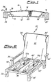
- the sprung structure according to the present invention is referred to generically as 10, and comprises essentially a U-shaped elongated support having a base 12 and two shorter side wings 14, 14'.
- the side wings 14 and 14' are inclined outward from the base 12 but they could be shaped differently, however within the limits imposed by the considerations to be presented below.
- Said base and side wings preferably form a single compact body. e.g. in the form of a rolled metal profile or in any case in a rigid or substantially rigid material.
- the free ends of the wings 14, 14' are connected by a length of an elastic belt, fitted under suitable tension and bound by its extremities to the ends of said wings 14, 14' in correspondence with its length extension and, preferably, by hooks or similar attachments 18, 18'.
- the latter may be fitted previously by techniques already known, to the extremities of the length of elastic belt with a platelet, and can be inserted into a suitably-shaped aperture in the ends of wings 14, 14', as will be described below. It should be noted that this hooking operation is carried out on a small-sized component which is substantially two-dimensional and standardized, and can be consequently easily mechanized, thus achieving considerable saving with respect to the substantially manual application of the belts by the manufacturers of articles of furniture or similar products.
- the belt is made up by interweaving suitably covered rubber filaments with substantially anelastic filaments in the warp and the weft, according to a well known technique. It has been found that it is appropriate to provide for lengths of fabric/rubber belt that are 80 millimetres wide and have a maximum elongation of 14%, which are mounted with a pre-tension which gives an elongation of 2 - 3%.
- a compression spring 20 is preferably fitted between the belt 16 and the base 12 of the rigid support, said spring being fixed on the base 12 with its lower end, while its upper end bears against the elastic belt 16, deforming it slightly in a direction away from the base 12, thus giving, inter alia, the bulging effect demanded by the sector.
- the spring 20 is a conical spring, and its greater diameter bears against the belt 16.
- the spring may be positioned at the mid-point of the structure, but it is better if it is towards one end of the structure, to give the said bulging effect in the required position and to give a better anatomical shape.
- the structure is completed by means of attachment of the same to the frame of the article of furniture or similar product, which means are formed by an extension 22, 22' of the upper wings 14, 14' forming an integral part of the same, having holes bored to take screws, nails or similar fasteners.
- the sprung structure as above described is incorporated into an article of furniture by fixing its ends 22, 22' to two opposite beams of the frame of the seat, armchair, divan or similar product, so that the elastic belts 16 are in line with the frame or in any case correctly positioned to carry out their springing function.
- two or more of the structures as above described are fixed parallel to each other on the same frame, depending on the size of the same frame. It has generally been found that, in the case of a seat, the best results have been found by attaching the structures to the back and forward cross-members of the frame, and that, due to the combined effect of the elastic belt and the metal spring, two structures alone are usually sufficient for the seat of an armchair or similar product, giving a perfectly anatomical support with considerable savings on material and labour compared to the known art.
- the springing structure according to the present invention is simple to produce and, above all, its production can be mechanized. Furthermore, it is easy to fit, as it will appear obvious to an expert in the art, unlike the systems of the present state of the art. It is a good combination of comfort and mechanical endurance and, thus, of durability; it drastically reduces the stress on the frame of the furniture component which supports it, thereby enabling a different, lighter frame to be used, since it no longer has to withstand the traction forces of the belts but only and exclusively the weight of the user.
- Fig. 2 shows an exemplary application of the sprung structure now described to the seat of an armchair.
- the frame of the armchair is generically indicated by reference 30; it comprises a back 32 with wings 34, 34', two arms 36,36', legs 38, 38'....
- the frame of the seat comprises a front cross-member 40, a rear cross-member 40' and two lateral members 42, 42'.
- the sprung structure of the present invention is of wide application and can be used not only in armchairs as described above, but also in divans, in all kinds of padded seats, in vehicle seats, and in beds - as spring to support the mattress.
- the sprung structure can be used in various parts of the seat e.g. in the backrest, when it is necessary or desirable.
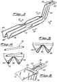
- Figs. 3 to 6 show a particularly advantageous embodiment of the support 12, 14, 14' which supports the belt and the spring 20.
- the support is made from a rolled metal profile e.g. in 12/10 mm P 01 sheet steel rolled to a W-profile to increase its moment of inertia and therefore its resistance.
- the two lateral walls 44 and 46 of the W-profile are forced toward the central fold 48, as shown in fig. 4 to retain the lowest coil 50 of the spring 20.
- the two lateral walls 44 and 46 of the W-profile are inwardly bent as shown in figs. 3 and 5 to contribute in a substantial manner in obtaining a high strength of the support to the stresses of the belt tending to pull the two wings 14, 14' towards the centre, varying the angle which these wings 14, 14' form with the base or the horizontal plane.
- This angle ⁇ (fig. 1) must be a compromise between the need to gain the maximum resistance to the stress imposed by the belts on the support wings 14, 14' and the need to leave sufficient room for downward movement of the platelet 52 (fig. 6) which connects the belt 16 to the hook 54 which is inserted into the hole 56 of the extension 22 of wings 14 and 14', which also has at least another hole 58 to mount it to the frame of the armchair or the like.
- Said angle ⁇ must be less than 90° but greater than 45° for the reasons stated above, the preference being for 55-60°.
- the sprung structure 10 can be complemented with a slidable holder 101, positioned on the base 12 of the U-shaped support.
- the slidable holder 101 has the function of holding a coil of the spring 20, while the other extremity of the spring is positioned under the elastic belt 16.
- the elastic belt 16 assumes other configurations, (in the example of Fig. 7, when the spring is in the position 20', the elastic belt is in the position 16'). In this way the shape and also, if desired, the tension of the elastic belt and of the furniture can be varied according to necessity.
- the slidable holder 101 for the spring 20 is composed of a small plate 102 which holds two nips 103, each one of them being provided with an hole 105.
- a guide 104 On the bottom of the plate 102 there is a guide 104 which allows the holder 101 to be slidably positioned on the U-shaped support 12.
- Fig. 9 shows a top wiew of the holder 101 in which are visible the nips 103 with their holes 105 over the plate 102.
- the holes 105 hold in position the coil of the spring 20.
Landscapes
- Springs (AREA)
- Mattresses And Other Support Structures For Chairs And Beds (AREA)
- Chair Legs, Seat Parts, And Backrests (AREA)
Claims (18)
- Eine Struktur (10) zum Abfedern von Teilen, die konstruiert sind, um das Gewicht eines menschlichen Körpers in Artikeln wie Mobelstücke, Sitze in Kraftfahrzeugen und ähnlichen Produkten, in der Weise, daß sie zumindest ein elastisches Band (16) umfassen, das aus Gummifilamenten gemacht ist, die mit im wesentlichen unelastischen Filamenten verwoben sind, wobei das Band (16) zwischen zwei gegenüberliegenden Seiten (26, 26') eines Rahmens (30) des Möbelstückes aufgehängt ist, dadurch gekennzeichnet, daß diese Struktur eine im wesentlichen starre U-förmige Unterstützung (12, 14, 14') und Mittel (24) besitzt, um es an den Rahmen des Möbelstücks oder ähnlichem zu befestigen, sowohl als auch Mittel (18), um das elastische Band (16) zwischen den beiden Armen (14, 14') der U-förmigen Unterstützung in Spannung zu halten.
- Eine Struktur (10) nach Anspruch 1, dadurch gekennzeichnet, daß es zumindest eine Spiralfeder (20) enthält, die unter Druck zwischen der Basis (12) der U-förmigen Unterstützung (12, 14, 14') und dem elastischen Band (16) positioniert ist.
- Eine Struktur (10) nach Anspruch 2, dadurch gekennzeichnet, daß jede dieser Federn (20) an verschiebbare Halter (101) befestigt ist, um damit die Position der Federn entlang der Basis der U-förmigen Unterstützung (12, 14, 14') zu regulieren.
- Eine Struktur (10) nach Anspruch 3, dadurch gekennzeichnet, daß der verschiebbare Halter (101) eine Platte (102) umfaßt, die mit einer Führung (104) ausgestattet ist, um auf der Basis der U-förmigen Unterstützung (12) zu halten und Mittel (103), um die Feder (20) auf der Platte (102) zu befestigen.
- Eine Struktur (10) nach Anspruch 4, dadurch gekennzeichnet, daß die Mittel zur Befestigung der Feder (20) an die Platte (102) zumindest einen Nippel (103) mit einem Loch (105) umfassen, um ein Ende der Spiralfeder (20) zu halten.
- Eine Struktur (10) nach Anspruch 2, dadurch gekennzeichnet, daß die Feder (20) konischer Form ist und das entgegengesetzte größere ende gegen das elastische Band (16) drückt.
- Eine Struktur (10) gemäß den Ansprüchen 2 oder 6, dadurch gekennzeichnet, daß die Feder (20) abseits von der Mitte der starren Unterstützung (12, 14, 14') positioniert ist.
- Eine Struktur (10) nach Anspruch 1, dadurch gekennzeichnet, daß das elastische Band (16) durch Haken (18, 18') und Bandhalterverbindungsplättchen an das freie Ende (22, 22') der Arme (14, 14') der starren Unterstützung verbunden ist.
- Eine Struktur (10) nach Anspruch 1, dadurch gekennzeichnet, daß die Mittel (24) zur Befestigung der Unterstützung integrale Verlängerungen an den Enden der Arme der U-förmigen Unterstützung umfassen, wobei die Verlängerungen Löcher besitzen, durch die Schrauben (24, 24'), Nägel oder ähnliche Haltemittel durchgeführt werden können.
- Eine Struktur (10) nach Anspruch 1, dadurch gekennzeichnet, daß das elastische Band (16) eine maximale elastische Ausdehnung von ungefähr 14 % besitzt und mit einer Vorspannung an der Unterstützung (12, 14, 14') befestigt ist, um das Band um 2 bis 3 % auszudehnen.
- Eine Struktur (10) nach den Ansprüchen 1 bis 10, dadurch gekennzeichnet, daß das elastische Band (16) eine Breite von ungefähr 80 mm besitzt.
- Eine Struktur (10) nach einem der vorigen Ansprüche, dadurch gekennzeichnet, daß die U-förmige Unterstützung (12, 14, 14') einen gewalzten Stahl mit einem W-förmigen Querschnittsprofil umfaßt.
- Eine Struktur (10) nach Anspruch 12, dadurch gekennzeichnet, daß die Seitenwände (44, 46) dieses W-förmigen Metallprofils an der Verbindung der Basis mit den Armen (14, 14') der U-förmigen Unterstützung nach innen gebogen sind.
- Eine Struktur (10) nach Anspruch 12, dadurch gekennzeichnet, daß diese Seitenwände (44, 46) dieser W-förmigen Metallprofile an den Stellen, an denen die Federn (20) befestigt sind, nach innen gebogen sind, um die unterste Spirale der Federn (20) zu halten.
- Eine Struktur (10) nach Anspruch 12, dadurch gekennzeichnet, daß der Winkel, der von den Armen (14, 14') der U-förmigen Unterstützung mit den Verlängerungen der Basis (12) derselbigen gebildet wird, zwischen 45° und 90° beträgt.
- Eine Struktur (10) nach Anspruch 15, dadurch gekennzeichnet, daß der Winkel zwischen den Armen (14, 14') der U-förmigen Unterstützung mit der Verlängerung der Basis (12) derselbigen zwischen 55° und 60° beträgt.
- Ein Möbelstuck wie zum Beispiel ein Sitz, Sessel, Diwan, Bett, Stuhl oder ein ähnliches Produkt, dadurch gekennzeichnet, daß es zumindest eine Federungsstruktur (10) nach den Ansprüchen 1 bis 16 enthält.
- Ein Artikel nach Anspruch 17, dadurch gekennzeichnet, daß es mindestens zwei oder mehr in einer Ebene parallel zueinander angeordnete Abfederungsstrukturen (10) umfaßt.
Applications Claiming Priority (5)
| Application Number | Priority Date | Filing Date | Title |
|---|---|---|---|
| ITMI942282 | 1994-11-11 | ||
| IT94MI002282A IT1276873B1 (it) | 1994-11-11 | 1994-11-11 | Struttura di molleggio in articoli di arredamento o simili |
| WOPCT/EP95/02588 | 1995-07-04 | ||
| EP9502588 | 1995-07-04 | ||
| PCT/EP1995/004321 WO1996014782A1 (en) | 1994-11-11 | 1995-11-03 | Sprung structure for articles of furniture or the like |
Publications (2)
| Publication Number | Publication Date |
|---|---|
| EP0790794A1 EP0790794A1 (de) | 1997-08-27 |
| EP0790794B1 true EP0790794B1 (de) | 1999-02-10 |
Family
ID=11369832
Family Applications (1)
| Application Number | Title | Priority Date | Filing Date |
|---|---|---|---|
| EP95938400A Expired - Lifetime EP0790794B1 (de) | 1994-11-11 | 1995-11-03 | Federstruktur für möbel und dergleichen |
Country Status (6)
| Country | Link |
|---|---|
| EP (1) | EP0790794B1 (de) |
| AU (1) | AU3980695A (de) |
| DE (1) | DE69507834T2 (de) |
| ES (1) | ES2130675T3 (de) |
| IT (1) | IT1276873B1 (de) |
| WO (1) | WO1996014782A1 (de) |
Families Citing this family (2)
| Publication number | Priority date | Publication date | Assignee | Title |
|---|---|---|---|---|
| DE202008005226U1 (de) * | 2008-04-15 | 2009-05-28 | Froli Kunststoffwerk Heinrich Fromme Ohg | Federung für eine Polsterung eines Sitzes, einer Rückenlehne bzw. Rückenschale |
| JP2022173658A (ja) * | 2021-05-10 | 2022-11-22 | 三協立山株式会社 | 家具 |
Family Cites Families (3)
| Publication number | Priority date | Publication date | Assignee | Title |
|---|---|---|---|---|
| DE32350C (de) * | FR. AUG. MÜLLER in Freiberg i. Sachsen, Bergstiftsgasse 1 o | Matratze mit bogenförmigen und geraden Spannfedern | ||
| FR540874A (fr) * | 1921-09-08 | 1922-07-19 | Sommier démontable | |
| FR45157E (fr) * | 1934-03-03 | 1935-07-06 | Compin Ets | Banquette élastique |
-
1994
- 1994-11-11 IT IT94MI002282A patent/IT1276873B1/it active IP Right Grant
-
1995
- 1995-11-03 ES ES95938400T patent/ES2130675T3/es not_active Expired - Lifetime
- 1995-11-03 EP EP95938400A patent/EP0790794B1/de not_active Expired - Lifetime
- 1995-11-03 DE DE69507834T patent/DE69507834T2/de not_active Expired - Fee Related
- 1995-11-03 WO PCT/EP1995/004321 patent/WO1996014782A1/en not_active Ceased
- 1995-11-03 AU AU39806/95A patent/AU3980695A/en not_active Abandoned
Also Published As
| Publication number | Publication date |
|---|---|
| AU3980695A (en) | 1996-06-06 |
| EP0790794A1 (de) | 1997-08-27 |
| WO1996014782A1 (en) | 1996-05-23 |
| DE69507834D1 (de) | 1999-03-25 |
| ES2130675T3 (es) | 1999-07-01 |
| ITMI942282A0 (it) | 1994-11-11 |
| IT1276873B1 (it) | 1997-11-03 |
| ITMI942282A1 (it) | 1996-05-11 |
| DE69507834T2 (de) | 1999-07-01 |
Similar Documents
| Publication | Publication Date | Title |
|---|---|---|
| US7025424B2 (en) | Chair back for a chair | |
| US5894664A (en) | Seating suspension assembly formation method | |
| US6722742B2 (en) | Suspension anchoring system for a seat | |
| US8240771B2 (en) | Mesh chair component | |
| US3988034A (en) | Chair and sofa construction | |
| US2260352A (en) | Combination seat and back | |
| US20040160109A1 (en) | Chair seat with firm but resilient front edge | |
| US4601516A (en) | Contoured chair | |
| WO2004107920A1 (en) | Comfort surface for seating | |
| US5544943A (en) | Seat construction and method | |
| US5658049A (en) | Separable recliner chair assembly | |
| US3310343A (en) | Furniture | |
| US3610688A (en) | Encapsulated cushion and spring deck assembly for seating structures | |
| US5615869A (en) | Torsion spring assembly | |
| EP0790794B1 (de) | Federstruktur für möbel und dergleichen | |
| US6264179B1 (en) | Seat assembly utilizing modular springs | |
| KR101052235B1 (ko) | 등받이 | |
| US4124201A (en) | Knockdown spring unit | |
| US5745935A (en) | Sinuous wire seat section sofa sleeper | |
| US4752976A (en) | Sofa sleeper having improved mattress supporting surface | |
| US2891603A (en) | Resilient retiform-fabric support surfaces | |
| EP1616749A2 (de) | Kraftfahrzeugsitz | |
| US6039404A (en) | Structure for suspension in articles of furniture or the like and method for the assembly of said structure | |
| EP0874574B1 (de) | Aufhängungsvorrichtung für möbel oder dergleichen und verfahren zur montage dieser vorrichtung | |
| US2764226A (en) | Spring assembly and units employed in the manufacture of same |
Legal Events
| Date | Code | Title | Description |
|---|---|---|---|
| PUAI | Public reference made under article 153(3) epc to a published international application that has entered the european phase |
Free format text: ORIGINAL CODE: 0009012 |
|
| 17P | Request for examination filed |
Effective date: 19970609 |
|
| AK | Designated contracting states |
Kind code of ref document: A1 Designated state(s): BE DE ES FR GB IT NL |
|
| GRAG | Despatch of communication of intention to grant |
Free format text: ORIGINAL CODE: EPIDOS AGRA |
|
| 17Q | First examination report despatched |
Effective date: 19980424 |
|
| GRAG | Despatch of communication of intention to grant |
Free format text: ORIGINAL CODE: EPIDOS AGRA |
|
| GRAH | Despatch of communication of intention to grant a patent |
Free format text: ORIGINAL CODE: EPIDOS IGRA |
|
| GRAH | Despatch of communication of intention to grant a patent |
Free format text: ORIGINAL CODE: EPIDOS IGRA |
|
| GRAA | (expected) grant |
Free format text: ORIGINAL CODE: 0009210 |
|
| RAP1 | Party data changed (applicant data changed or rights of an application transferred) |
Owner name: MAGUSTA TRADING E INVESTIMENTOS, LDA |
|
| AK | Designated contracting states |
Kind code of ref document: B1 Designated state(s): BE DE ES FR GB IT NL |
|
| ITF | It: translation for a ep patent filed | ||
| REF | Corresponds to: |
Ref document number: 69507834 Country of ref document: DE Date of ref document: 19990325 |
|
| ET | Fr: translation filed | ||
| REG | Reference to a national code |
Ref country code: ES Ref legal event code: FG2A Ref document number: 2130675 Country of ref document: ES Kind code of ref document: T3 |
|
| PLBE | No opposition filed within time limit |
Free format text: ORIGINAL CODE: 0009261 |
|
| STAA | Information on the status of an ep patent application or granted ep patent |
Free format text: STATUS: NO OPPOSITION FILED WITHIN TIME LIMIT |
|
| 26N | No opposition filed | ||
| PGFP | Annual fee paid to national office [announced via postgrant information from national office to epo] |
Ref country code: GB Payment date: 20011105 Year of fee payment: 7 |
|
| PGFP | Annual fee paid to national office [announced via postgrant information from national office to epo] |
Ref country code: DE Payment date: 20011117 Year of fee payment: 7 |
|
| PGFP | Annual fee paid to national office [announced via postgrant information from national office to epo] |
Ref country code: BE Payment date: 20011119 Year of fee payment: 7 |
|
| PGFP | Annual fee paid to national office [announced via postgrant information from national office to epo] |
Ref country code: FR Payment date: 20011129 Year of fee payment: 7 |
|
| PGFP | Annual fee paid to national office [announced via postgrant information from national office to epo] |
Ref country code: NL Payment date: 20011130 Year of fee payment: 7 Ref country code: ES Payment date: 20011130 Year of fee payment: 7 |
|
| REG | Reference to a national code |
Ref country code: GB Ref legal event code: IF02 |
|
| PG25 | Lapsed in a contracting state [announced via postgrant information from national office to epo] |
Ref country code: GB Free format text: LAPSE BECAUSE OF NON-PAYMENT OF DUE FEES Effective date: 20021103 |
|
| PG25 | Lapsed in a contracting state [announced via postgrant information from national office to epo] |
Ref country code: ES Free format text: LAPSE BECAUSE OF NON-PAYMENT OF DUE FEES Effective date: 20021104 |
|
| PG25 | Lapsed in a contracting state [announced via postgrant information from national office to epo] |
Ref country code: BE Free format text: LAPSE BECAUSE OF NON-PAYMENT OF DUE FEES Effective date: 20021130 |
|
| BERE | Be: lapsed |
Owner name: *MAGUSTA TRADING E INVESTIMENTOS LDA Effective date: 20021130 |
|
| PG25 | Lapsed in a contracting state [announced via postgrant information from national office to epo] |
Ref country code: NL Free format text: LAPSE BECAUSE OF NON-PAYMENT OF DUE FEES Effective date: 20030601 |
|
| PG25 | Lapsed in a contracting state [announced via postgrant information from national office to epo] |
Ref country code: DE Free format text: LAPSE BECAUSE OF NON-PAYMENT OF DUE FEES Effective date: 20030603 |
|
| GBPC | Gb: european patent ceased through non-payment of renewal fee | ||
| PG25 | Lapsed in a contracting state [announced via postgrant information from national office to epo] |
Ref country code: FR Free format text: LAPSE BECAUSE OF NON-PAYMENT OF DUE FEES Effective date: 20030731 |
|
| NLV4 | Nl: lapsed or anulled due to non-payment of the annual fee |
Effective date: 20030601 |
|
| REG | Reference to a national code |
Ref country code: FR Ref legal event code: ST |
|
| REG | Reference to a national code |
Ref country code: ES Ref legal event code: FD2A Effective date: 20031213 |
|
| PGFP | Annual fee paid to national office [announced via postgrant information from national office to epo] |
Ref country code: IT Payment date: 20061130 Year of fee payment: 12 |
|
| PG25 | Lapsed in a contracting state [announced via postgrant information from national office to epo] |
Ref country code: IT Free format text: LAPSE BECAUSE OF NON-PAYMENT OF DUE FEES Effective date: 20071103 |