EP0790666A1 - Structure combinée d'une antenne hélice et une plaque diélectrique - Google Patents
Structure combinée d'une antenne hélice et une plaque diélectrique Download PDFInfo
- Publication number
- EP0790666A1 EP0790666A1 EP97301011A EP97301011A EP0790666A1 EP 0790666 A1 EP0790666 A1 EP 0790666A1 EP 97301011 A EP97301011 A EP 97301011A EP 97301011 A EP97301011 A EP 97301011A EP 0790666 A1 EP0790666 A1 EP 0790666A1
- Authority
- EP
- European Patent Office
- Prior art keywords
- antenna
- helix
- accordance
- dielectric plate
- frequency
- Prior art date
- Legal status (The legal status is an assumption and is not a legal conclusion. Google has not performed a legal analysis and makes no representation as to the accuracy of the status listed.)
- Withdrawn
Links
Images


Classifications
-
- H—ELECTRICITY
- H01—ELECTRIC ELEMENTS
- H01Q—ANTENNAS, i.e. RADIO AERIALS
- H01Q11/00—Electrically-long antennas having dimensions more than twice the shortest operating wavelength and consisting of conductive active radiating elements
- H01Q11/02—Non-resonant antennas, e.g. travelling-wave antenna
- H01Q11/08—Helical antennas
-
- H—ELECTRICITY
- H01—ELECTRIC ELEMENTS
- H01Q—ANTENNAS, i.e. RADIO AERIALS
- H01Q1/00—Details of, or arrangements associated with, antennas
- H01Q1/36—Structural form of radiating elements, e.g. cone, spiral, umbrella; Particular materials used therewith
- H01Q1/362—Structural form of radiating elements, e.g. cone, spiral, umbrella; Particular materials used therewith for broadside radiating helical antennas
Definitions
- the present invention relates to an antenna, particularly a high-frequency antenna structure, and more particularly a helical antenna structure provided with support elements.
- a helix may be a cylindrical coil conductor, such as employed in high-frequency electronics in, amongst other things, resonator and antenna structures, and in particular in portable radio appliances, such as mobile telephones.
- Antennae in which use is made of a helical antenna supported on a support plate inside the helix, have been proposed in GB Patent Application No 2 280 789.
- the publication in question contains a proposal for a structure where strip areas, which consist of a conducting material and which constitute a helix antenna, are formed on the surface of a dielectric substrate.
- the conducting areas are for example created on one side only of the substrate, which is bent into the form of a cylinder, thus producing a helical antenna.
- Another method is to produce on both sides of the substrate conductor strips which are joined to conductor strips on the opposite side, so that a helical antenna element is obtained.
- US Patent No 4 935 747 proposes a helix antenna where the helix is placed around a support member which in cross section has the shape of a cross. The helix and support member are against a reflector, on which a strip line is formed for antenna feed.
- the support member inside the helix is intended to retain and support the helical form, only the helical component being a radiator.
- the problem with such a solution is that other possible components of the antenna, such as the transmission line or the whip antenna, have to be connected to the helix by other means and have to be attached to the support structure of the antenna by other means.
- the combination of a dielectric plate and a helix is also employed in the helix-comb filter produced by LK Products Oy, which is described in Finnish Patent No 78198.
- the patent also proposes a resonator structure in which there is a cylindrical coil conductor forming the helix-resonator, which conductor is supported on a plate situated inside it and made from an insulating material. On the insulation plate strip lines are used to form an electrical circuit to which the helix resonator is connected.
- This patent does not however concern use of the structure as an antenna since in the design of resonator structures elimination of radiation to the environment is aimed for.
- European patent publication EP 0 590 534 describes the use of a helix in combination with a dipole antenna pattern formed on a dielectric plate.
- the application describes an antenna, which can be retracted into a housing, whereby conductive patterns on a dielectric plate form both a sliding contact and an antenna pattern.
- the publication does not however present a structure, which could easily be used in mass production for producing many different types of antenna.
- an antenna for a communication device operating at radio frequency which antenna comprises a cylindrical coil conductor, which forms a helix, and a dielectric plate for mechanical support of the said helix, this helix being attached to the said dielectric plate with the aid of at least one attachment point, characterized in that the dielectric plate includes an electrically conductive conductor pattern, which is in electrical contact with the said helix. Ideally the electrically conductive conductor pattern at least in part extends inside the helix.
- a preferred embodiment in accordance with the present invention may provide a small and versatile helix antenna structure.
- a preferred embodiment in accordance with the invention may also provide an antenna structure the characteristics of which may be closely adhered to in series production. Such a preferred embodiment may be attained by forming other parts of the antenna, such as transmission lines, radiators and matching elements on the support plate which supports the helix with, for example, the aid of conductive patterning formed on the surface thereof.
- a characteristic of a preferred embodiment in accordance with the invention may be that there is on the dielectric plate an electrically conductive conductor pattern, which is in electrical contact with the said helix.
- Embodiments in accordance with the invention may be based upon a combination of a dielectric plate and a helix such that the plate supports the helix. On the plate may be attachment points for attaching the helix thereto. Conductor patterns may also be formed on the plate, with the aid of which at least one of the following functions is realized: antenna feed, matching elements, or a radiator formed on the dielectric plate. With such antenna structures it is possible to provide balanced, unbalanced and coaxial feeds.
- Embodiments in accordance with the invention may provide very versatile antenna structures with a high degree of dimensional accuracy and reproducibility compared with known antenna solutions.
- the structure may make it possible to produce, for example, a simple, normal helix antenna, a shortened whip antenna with a helix and/or end capacitance and a helix-dipole antenna.
- This structure may also be suitable for the production of dual-band antennae, where the antenna is in tune at two different frequencies. In that case the operation of two frequencies may be achieved either by two overlapping or nesting helices, or by means of a pattern on the dielectric plate which acts as an antenna and/or a transmission line feeding the antenna.
- an antenna in accordance with the invention may also be attached to a separate connector, and may be protected with an elastic material.
- Figure 1 is an isometric view illustrating the principle of the antenna structure, modifications of which are shown from the side in other drawings.
- Figure 1 shows the dielectric plate 1 which forms part of the antenna and a helix 2 wound around it.
- the dielectric plate may for example be a circuit board on which a conductor pattern is formed.
- Figure 2 shows the structure in question viewed from two different sides ( Figures 2(a) and (b)) and from below/above Figure 2(c)). From the figures the important basic components of the structure can be seen: the dielectric plate 1, which extends through the helix and supports it, and the patterns 3a, 3b and 4 on the dielectric plate. The functions of the dielectric plate 1 and of the patterns thereon are varied, depending as they do upon the type of antenna to be produced with the structure. For example, in Figure 2(a) attachment points 3a and 3b for attachment of the helix are marked, and with these the helix may be locked, for example by pasting, onto the dielectric plate 1; also marked is the microstrip 4 which acts as a transmission line. With the patterning on the dielectric plate 1 it is possible to obtain other functions, as illustrated in the following favourable embodiments.
- a whip antenna shortened with a helix 2 is shown, where part of the pattern 5 of the dielectric plate 1 now acts as a radiator and not as a transmission line. The other part of the pattern still acts as the transmission line 4 and as attachment points 3a and 3b.
- a combination is formed of a helix antenna supported on the dielectric plate 1 and attached thereto, and of a whip antenna in dielectric plate 1.
- the whip or elongate antenna may, as shown in the drawing, be either at the bottom or the top of the helix, but in such a way that it is attached to the lower part, or similarly to the upper part, of the helix.
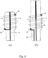
- Figures 4(a) and 4(b) show an antenna of two frequencies achieved with a structure according to the invention, where the helix 2 is in tune at the lower frequency and the antenna 5 formed in the dielectric plate is in tune at the higher frequency.
- Being in tune at a particular frequency means that the frequency in question is the antenna's resonance frequency. At this frequency the antenna operates more effectively than at other frequencies).
- the transmission line 4 may feed both the helix 2 and the whip antenna 5 ( Figure 4(a)), or separate feeds 4a and 4b may be provided for antennae 2 and 5 ( Figure 4(b)).
- the coils of the helix 2 surround or enclose the antenna 5.
- the antenna 5 extends inside the helix 2.
- Figures 5(a) and 5(b) illustrate ways of physically shortening the length of the whip antenna 5 in the direction of the longitudinal axis of the antenna, for example by a zigzag pattern (Figure 5(a)) or by widening the conductor pattern at the top of the antenna ( Figure 5(b)).
- the above-mentioned methods are in themselves widely known methods for shortening a whip antenna, if one wishes to include two antennae operating at different frequencies within almost the same physical length.
- the transmission line 4a of the helix 2 continues as transmission line 4b to the antenna 5 formed in the dielectric plate 1.
- the antennae according to Figures 5(a) and 5(b) may for example be realized by using different transmission lines in accordance with Figure 4(b).
- Figure 6(a) shows a centrally fed helix-dipole antenna, which may be produced with a structure in accordance with the invention.
- the antenna consists of two helices 2a and 2b, which are fed with a microstrip transmission line 4 from the centre of the structure. Both helices may be attached to the dielectric plate 1 with their own attachment points 3a, 3b and 3a', 3b'.
- Figure 6(b) shows the same structure, but now the helices 2a and 2b are fed with a balanced transmission line 4.
- Figure 6(c) shows a dual-band antenna, which consists of two helices 2a and 2b one on top of the other. Both are fed with different transmission lines 4a and 4b.
- the dielectric plate 1 By shaping the dielectric plate 1 slightly differently, it is possible to produce structures with the solutions according to Figure 7(a) and 7(b), in which the helices 2a and 2b are nested.
- the dielectric plate shown in these drawings comprises a support member for the helix antenna 2b of larger diameter and a support member for the helix antenna 2a of smaller diameter.
- the inner helix antenna 2a extends into the cavities made in the dielectric plate 1, so that the outer helix and the inner helix partly overlap.
- the inner helix 2a in Figure 7(a) is fed with transmission line 4 and the helix 2b is a parasitic element, which increases the bandwidth of the antenna.
- Figure 7(b) shows a similar nesting arrangement of the helices.
- a further advantage of a structure in accordance with the invention is the opportunity which it offers for having impedance matching devices in the antenna structure itself on the dielectric plate 1, as shown in Figure 8. It is then possible to produce antennae of different electrical lengths and to adjust the impedance to that required, whereby it can be done with the least loss, or as close as possible to the feed point.
- the impedance elements 6 may be inductances or capacitances, created for example by strip line technology, or separate components.
- Figure 8 also shows the coils of the helix 2 surrounding the antenna 5 as in Figure 4(a).
- a structure in accordance with the invention may be formed as part of a radio device's own circuit board, or it may be attached thereto for example by soldering or by a circuit board connector.
- Figures 9(a) and 9(b) show a favourable way of attaching a structure in accordance with the invention to a separate connector 8.
- the dielectric plate 1 may extend through the aperture in the connector 8.
- the antenna may be attached for example by die casting into a protective casing 7.
- a high-frequency signal may be fed either directly to the lower end of the helix, as in Figure 9(a), or the connection may be made coaxial, as in Figure 9(b).
- the conductor 4 then acts as the inner wire of the coaxial conductor. Transmission may be effected for example by pegging to a point of the impedance suitable for the helix.
- Figure 9(a) also shows the antenna 5 extending inside the helix 2.
- the present invention is not restricted to a particular application but may be used in antennae in different applications and at different frequencies, preferably at UHF and VHF radio frequencies.
- the structures presented above are by way of example.
- the dielectric plate may be of different forms.
- the number of helices, the transmission method employed in the antenna structure and the adapting devices effected may vary according to the antenna structure.
- the structure may be used to advantage in mobile telephone antennae, among other things.
- a preferred embodiment may relate to a particular structure of high-frequency antenna, which comprises a support element provided with a cylindrical coil conductor which forms a helix.
- a support element On the support element it is possible to form, for example by means of a conductive coating, the electrical parts of the antenna, such as the attachment points for the helix and for other parts, feeder lines, emitters or impedance matching devices.
- the electrical parts of the antenna such as the attachment points for the helix and for other parts, feeder lines, emitters or impedance matching devices.
Landscapes
- Details Of Aerials (AREA)
Applications Claiming Priority (2)
| Application Number | Priority Date | Filing Date | Title |
|---|---|---|---|
| FI960711A FI106895B (fi) | 1996-02-16 | 1996-02-16 | Dielektrisen levyn ja heliksiantennin yhdistetty rakenne |
| FI960711 | 1996-02-16 |
Publications (1)
| Publication Number | Publication Date |
|---|---|
| EP0790666A1 true EP0790666A1 (fr) | 1997-08-20 |
Family
ID=8545472
Family Applications (1)
| Application Number | Title | Priority Date | Filing Date |
|---|---|---|---|
| EP97301011A Withdrawn EP0790666A1 (fr) | 1996-02-16 | 1997-02-17 | Structure combinée d'une antenne hélice et une plaque diélectrique |
Country Status (3)
| Country | Link |
|---|---|
| US (1) | US5990848A (fr) |
| EP (1) | EP0790666A1 (fr) |
| FI (1) | FI106895B (fr) |
Cited By (16)
| Publication number | Priority date | Publication date | Assignee | Title |
|---|---|---|---|---|
| EP0831545A2 (fr) * | 1996-09-19 | 1998-03-25 | Matsushita Electric Industrial Co., Ltd. | Dispositif d'antenne |
| WO1999014819A1 (fr) * | 1997-09-15 | 1999-03-25 | Ericsson, Inc. | Antenne helicoidale a deux bandes de frequence a element parasite |
| WO1999026315A1 (fr) * | 1997-11-14 | 1999-05-27 | Moteco Ab | Antenne pour bandes a deux frequences |
| WO1999026314A1 (fr) * | 1997-11-14 | 1999-05-27 | Moteco Ab | Antenne pour bandes a deux frequences |
| FR2790600A1 (fr) * | 1999-03-02 | 2000-09-08 | Pierre Piccaluga | Antenne a differentiel de reception |
| US6127979A (en) * | 1998-02-27 | 2000-10-03 | Motorola, Inc. | Antenna adapted to operate in a plurality of frequency bands |
| US6275198B1 (en) | 2000-01-11 | 2001-08-14 | Motorola, Inc. | Wide band dual mode antenna |
| WO2001061782A1 (fr) * | 2000-02-18 | 2001-08-23 | Allgon Ab | Dispositif de contact, dispositif antenne comportant un dispositif de contact et un dispositif de communication |
| US6336036B1 (en) | 1998-07-08 | 2002-01-01 | Ericsson Inc. | Retractable dual-band tapped helical radiotelephone antennas |
| US6501428B1 (en) | 1998-01-30 | 2002-12-31 | Moteco Ab | Antenna device for dual frequency bands |
| KR20030080151A (ko) * | 2002-04-04 | 2003-10-11 | 주식회사 이엠따블유안테나 | 듀얼밴드형 안테나 |
| KR20030082327A (ko) * | 2002-04-17 | 2003-10-22 | 주식회사 이엠따블유안테나 | 듀얼밴드형 안테나 |
| EP1643594A2 (fr) * | 2004-09-30 | 2006-04-05 | Etop Technology Co., Ltd. | antenne |
| EP1675214A1 (fr) | 2004-12-23 | 2006-06-28 | CALEARO ANTENNE S.P.A. a socio unico | Antenne multibande pour véhicule |
| EP2287966A1 (fr) * | 2009-08-17 | 2011-02-23 | Delphi Delco Electronics Europe GmbH | Mât d'antenne pour une antenne en forme de mât pour plusieurs services radio |
| EP3107148A1 (fr) * | 2015-06-19 | 2016-12-21 | BIOTRONIK SE & Co. KG | Dispositif médical implantable comprenant un élément électronique à haute fréquence |
Families Citing this family (176)
| Publication number | Priority date | Publication date | Assignee | Title |
|---|---|---|---|---|
| US5977931A (en) * | 1997-07-15 | 1999-11-02 | Antenex, Inc. | Low visibility radio antenna with dual polarization |
| KR100291554B1 (ko) * | 1998-09-25 | 2001-07-12 | 김춘호 | 이동통신단말기용이중대역안테나 |
| US6525692B2 (en) * | 1998-09-25 | 2003-02-25 | Korea Electronics Technology Institute | Dual-band antenna for mobile telecommunication units |
| US6297784B1 (en) * | 1998-11-02 | 2001-10-02 | Auden Techno Corp. | Bi-frequency cellular telephone antenna |
| GB2344938A (en) * | 1998-12-18 | 2000-06-21 | Nokia Mobile Phones Ltd | A multiple band, multiple co-axial element antenna |
| US6359598B1 (en) | 1999-05-03 | 2002-03-19 | Centurion Wireless Technologies, Inc. | Plastic or die-cast antenna for a wireless communications device |
| US6229495B1 (en) * | 1999-08-06 | 2001-05-08 | Bae Systems Advanced Systems | Dual-point-feed broadband whip antenna |
| US6219007B1 (en) * | 1999-08-23 | 2001-04-17 | The Whitaker Corporation | Antenna assembly |
| US6292145B1 (en) * | 2000-02-02 | 2001-09-18 | Sun Yu | Angled antenna for portable telephone |
| JP2002359514A (ja) * | 2001-05-31 | 2002-12-13 | Anten Corp | ヘリカルアンテナ |
| US6608605B2 (en) * | 2001-12-10 | 2003-08-19 | Hewlett-Packard Development Company, L.P. | Multi-band uniform helical antenna and communication device having the same |
| US6559811B1 (en) | 2002-01-22 | 2003-05-06 | Motorola, Inc. | Antenna with branching arrangement for multiple frequency bands |
| AU2003233168A1 (en) * | 2002-06-06 | 2003-12-22 | Galtronics Ltd. | Multi-band improvements to a monopole helical_antenna |
| US7038636B2 (en) * | 2003-06-18 | 2006-05-02 | Ems Technologies Cawada, Ltd. | Helical antenna |
| US7400303B1 (en) * | 2003-10-21 | 2008-07-15 | R.A. Miller Industries, Inc. | Antenna with keyed coupling |
| US7209096B2 (en) * | 2004-01-22 | 2007-04-24 | Antenex, Inc. | Low visibility dual band antenna with dual polarization |
| WO2005076409A1 (fr) * | 2004-01-30 | 2005-08-18 | Fractus S.A. | Antennes unipolaires multibandes pour dispositifs de communications fonctionnant sur un reseau mobile |
| US7183998B2 (en) * | 2004-06-02 | 2007-02-27 | Sciperio, Inc. | Micro-helix antenna and methods for making same |
| CN1989652B (zh) | 2004-06-28 | 2013-03-13 | 脉冲芬兰有限公司 | 天线部件 |
| KR100744335B1 (ko) * | 2004-10-26 | 2007-07-30 | 삼성전자주식회사 | 휴대용 단말기의 안테나 장치 |
| JP4699931B2 (ja) * | 2005-06-28 | 2011-06-15 | 株式会社日本自動車部品総合研究所 | アンテナ |
| FI20055420A0 (fi) | 2005-07-25 | 2005-07-25 | Lk Products Oy | Säädettävä monikaista antenni |
| FI119009B (fi) | 2005-10-03 | 2008-06-13 | Pulse Finland Oy | Monikaistainen antennijärjestelmä |
| FI118782B (fi) | 2005-10-14 | 2008-03-14 | Pulse Finland Oy | Säädettävä antenni |
| FI119577B (fi) * | 2005-11-24 | 2008-12-31 | Pulse Finland Oy | Monikaistainen antennikomponentti |
| US8618990B2 (en) | 2011-04-13 | 2013-12-31 | Pulse Finland Oy | Wideband antenna and methods |
| US10211538B2 (en) | 2006-12-28 | 2019-02-19 | Pulse Finland Oy | Directional antenna apparatus and methods |
| FI20075269A0 (fi) | 2007-04-19 | 2007-04-19 | Pulse Finland Oy | Menetelmä ja järjestely antennin sovittamiseksi |
| FI120427B (fi) | 2007-08-30 | 2009-10-15 | Pulse Finland Oy | Säädettävä monikaista-antenni |
| US20090243942A1 (en) * | 2008-03-31 | 2009-10-01 | Marko Tapio Autti | Multiband antenna |
| TWM369549U (en) * | 2008-07-16 | 2009-11-21 | Unication Co Ltd | Miniature dual-band antenna |
| US20110013351A1 (en) * | 2009-07-20 | 2011-01-20 | Mobile Monitor Technologies, Llc | Portable monitor |
| FI20096134A0 (fi) | 2009-11-03 | 2009-11-03 | Pulse Finland Oy | Säädettävä antenni |
| FI20096251A0 (sv) | 2009-11-27 | 2009-11-27 | Pulse Finland Oy | MIMO-antenn |
| US8847833B2 (en) | 2009-12-29 | 2014-09-30 | Pulse Finland Oy | Loop resonator apparatus and methods for enhanced field control |
| FI20105158A (fi) | 2010-02-18 | 2011-08-19 | Pulse Finland Oy | Kuorisäteilijällä varustettu antenni |
| US9406998B2 (en) | 2010-04-21 | 2016-08-02 | Pulse Finland Oy | Distributed multiband antenna and methods |
| FI20115072A0 (fi) | 2011-01-25 | 2011-01-25 | Pulse Finland Oy | Moniresonanssiantenni, -antennimoduuli ja radiolaite |
| US9673507B2 (en) | 2011-02-11 | 2017-06-06 | Pulse Finland Oy | Chassis-excited antenna apparatus and methods |
| US8648752B2 (en) | 2011-02-11 | 2014-02-11 | Pulse Finland Oy | Chassis-excited antenna apparatus and methods |
| US8866689B2 (en) | 2011-07-07 | 2014-10-21 | Pulse Finland Oy | Multi-band antenna and methods for long term evolution wireless system |
| US9450291B2 (en) | 2011-07-25 | 2016-09-20 | Pulse Finland Oy | Multiband slot loop antenna apparatus and methods |
| US9123990B2 (en) | 2011-10-07 | 2015-09-01 | Pulse Finland Oy | Multi-feed antenna apparatus and methods |
| US9531058B2 (en) | 2011-12-20 | 2016-12-27 | Pulse Finland Oy | Loosely-coupled radio antenna apparatus and methods |
| US9484619B2 (en) | 2011-12-21 | 2016-11-01 | Pulse Finland Oy | Switchable diversity antenna apparatus and methods |
| US8988296B2 (en) | 2012-04-04 | 2015-03-24 | Pulse Finland Oy | Compact polarized antenna and methods |
| US9979078B2 (en) | 2012-10-25 | 2018-05-22 | Pulse Finland Oy | Modular cell antenna apparatus and methods |
| JP5691035B2 (ja) * | 2012-10-25 | 2015-04-01 | 株式会社ビートソニック | ヘリカルアンテナ |
| US10069209B2 (en) | 2012-11-06 | 2018-09-04 | Pulse Finland Oy | Capacitively coupled antenna apparatus and methods |
| US9647338B2 (en) | 2013-03-11 | 2017-05-09 | Pulse Finland Oy | Coupled antenna structure and methods |
| US10079428B2 (en) | 2013-03-11 | 2018-09-18 | Pulse Finland Oy | Coupled antenna structure and methods |
| US9484628B2 (en) * | 2013-05-09 | 2016-11-01 | Think Wireless, Inc | Multiband frequency antenna |
| US9999038B2 (en) | 2013-05-31 | 2018-06-12 | At&T Intellectual Property I, L.P. | Remote distributed antenna system |
| US9525524B2 (en) | 2013-05-31 | 2016-12-20 | At&T Intellectual Property I, L.P. | Remote distributed antenna system |
| US9634383B2 (en) | 2013-06-26 | 2017-04-25 | Pulse Finland Oy | Galvanically separated non-interacting antenna sector apparatus and methods |
| FR3008550B1 (fr) * | 2013-07-15 | 2015-08-21 | Inst Mines Telecom Telecom Bretagne | Antenne de type bouchon et structure antennaire et ensemble antennaire associes |
| US8897697B1 (en) | 2013-11-06 | 2014-11-25 | At&T Intellectual Property I, Lp | Millimeter-wave surface-wave communications |
| US9680212B2 (en) | 2013-11-20 | 2017-06-13 | Pulse Finland Oy | Capacitive grounding methods and apparatus for mobile devices |
| US9590308B2 (en) | 2013-12-03 | 2017-03-07 | Pulse Electronics, Inc. | Reduced surface area antenna apparatus and mobile communications devices incorporating the same |
| US9350081B2 (en) | 2014-01-14 | 2016-05-24 | Pulse Finland Oy | Switchable multi-radiator high band antenna apparatus |
| US9973228B2 (en) | 2014-08-26 | 2018-05-15 | Pulse Finland Oy | Antenna apparatus with an integrated proximity sensor and methods |
| US9948002B2 (en) | 2014-08-26 | 2018-04-17 | Pulse Finland Oy | Antenna apparatus with an integrated proximity sensor and methods |
| US9722308B2 (en) | 2014-08-28 | 2017-08-01 | Pulse Finland Oy | Low passive intermodulation distributed antenna system for multiple-input multiple-output systems and methods of use |
| US9768833B2 (en) | 2014-09-15 | 2017-09-19 | At&T Intellectual Property I, L.P. | Method and apparatus for sensing a condition in a transmission medium of electromagnetic waves |
| US10063280B2 (en) | 2014-09-17 | 2018-08-28 | At&T Intellectual Property I, L.P. | Monitoring and mitigating conditions in a communication network |
| US9615269B2 (en) | 2014-10-02 | 2017-04-04 | At&T Intellectual Property I, L.P. | Method and apparatus that provides fault tolerance in a communication network |
| US9685992B2 (en) | 2014-10-03 | 2017-06-20 | At&T Intellectual Property I, L.P. | Circuit panel network and methods thereof |
| US9503189B2 (en) | 2014-10-10 | 2016-11-22 | At&T Intellectual Property I, L.P. | Method and apparatus for arranging communication sessions in a communication system |
| US9973299B2 (en) | 2014-10-14 | 2018-05-15 | At&T Intellectual Property I, L.P. | Method and apparatus for adjusting a mode of communication in a communication network |
| US9769020B2 (en) | 2014-10-21 | 2017-09-19 | At&T Intellectual Property I, L.P. | Method and apparatus for responding to events affecting communications in a communication network |
| US9653770B2 (en) | 2014-10-21 | 2017-05-16 | At&T Intellectual Property I, L.P. | Guided wave coupler, coupling module and methods for use therewith |
| US9627768B2 (en) | 2014-10-21 | 2017-04-18 | At&T Intellectual Property I, L.P. | Guided-wave transmission device with non-fundamental mode propagation and methods for use therewith |
| US9312919B1 (en) | 2014-10-21 | 2016-04-12 | At&T Intellectual Property I, Lp | Transmission device with impairment compensation and methods for use therewith |
| US9577306B2 (en) | 2014-10-21 | 2017-02-21 | At&T Intellectual Property I, L.P. | Guided-wave transmission device and methods for use therewith |
| US9780834B2 (en) | 2014-10-21 | 2017-10-03 | At&T Intellectual Property I, L.P. | Method and apparatus for transmitting electromagnetic waves |
| US9800327B2 (en) | 2014-11-20 | 2017-10-24 | At&T Intellectual Property I, L.P. | Apparatus for controlling operations of a communication device and methods thereof |
| US10009067B2 (en) | 2014-12-04 | 2018-06-26 | At&T Intellectual Property I, L.P. | Method and apparatus for configuring a communication interface |
| US10340573B2 (en) | 2016-10-26 | 2019-07-02 | At&T Intellectual Property I, L.P. | Launcher with cylindrical coupling device and methods for use therewith |
| US9742462B2 (en) | 2014-12-04 | 2017-08-22 | At&T Intellectual Property I, L.P. | Transmission medium and communication interfaces and methods for use therewith |
| US9954287B2 (en) | 2014-11-20 | 2018-04-24 | At&T Intellectual Property I, L.P. | Apparatus for converting wireless signals and electromagnetic waves and methods thereof |
| US9461706B1 (en) | 2015-07-31 | 2016-10-04 | At&T Intellectual Property I, Lp | Method and apparatus for exchanging communication signals |
| US10243784B2 (en) | 2014-11-20 | 2019-03-26 | At&T Intellectual Property I, L.P. | System for generating topology information and methods thereof |
| US9997819B2 (en) | 2015-06-09 | 2018-06-12 | At&T Intellectual Property I, L.P. | Transmission medium and method for facilitating propagation of electromagnetic waves via a core |
| US9544006B2 (en) | 2014-11-20 | 2017-01-10 | At&T Intellectual Property I, L.P. | Transmission device with mode division multiplexing and methods for use therewith |
| US9876570B2 (en) | 2015-02-20 | 2018-01-23 | At&T Intellectual Property I, Lp | Guided-wave transmission device with non-fundamental mode propagation and methods for use therewith |
| US9749013B2 (en) | 2015-03-17 | 2017-08-29 | At&T Intellectual Property I, L.P. | Method and apparatus for reducing attenuation of electromagnetic waves guided by a transmission medium |
| US10224981B2 (en) | 2015-04-24 | 2019-03-05 | At&T Intellectual Property I, Lp | Passive electrical coupling device and methods for use therewith |
| US9705561B2 (en) | 2015-04-24 | 2017-07-11 | At&T Intellectual Property I, L.P. | Directional coupling device and methods for use therewith |
| US9793954B2 (en) | 2015-04-28 | 2017-10-17 | At&T Intellectual Property I, L.P. | Magnetic coupling device and methods for use therewith |
| US9490869B1 (en) | 2015-05-14 | 2016-11-08 | At&T Intellectual Property I, L.P. | Transmission medium having multiple cores and methods for use therewith |
| US9871282B2 (en) | 2015-05-14 | 2018-01-16 | At&T Intellectual Property I, L.P. | At least one transmission medium having a dielectric surface that is covered at least in part by a second dielectric |
| US9748626B2 (en) | 2015-05-14 | 2017-08-29 | At&T Intellectual Property I, L.P. | Plurality of cables having different cross-sectional shapes which are bundled together to form a transmission medium |
| US10650940B2 (en) | 2015-05-15 | 2020-05-12 | At&T Intellectual Property I, L.P. | Transmission medium having a conductive material and methods for use therewith |
| US9917341B2 (en) | 2015-05-27 | 2018-03-13 | At&T Intellectual Property I, L.P. | Apparatus and method for launching electromagnetic waves and for modifying radial dimensions of the propagating electromagnetic waves |
| US9912381B2 (en) | 2015-06-03 | 2018-03-06 | At&T Intellectual Property I, Lp | Network termination and methods for use therewith |
| US9866309B2 (en) | 2015-06-03 | 2018-01-09 | At&T Intellectual Property I, Lp | Host node device and methods for use therewith |
| US10812174B2 (en) | 2015-06-03 | 2020-10-20 | At&T Intellectual Property I, L.P. | Client node device and methods for use therewith |
| US9913139B2 (en) | 2015-06-09 | 2018-03-06 | At&T Intellectual Property I, L.P. | Signal fingerprinting for authentication of communicating devices |
| US9820146B2 (en) | 2015-06-12 | 2017-11-14 | At&T Intellectual Property I, L.P. | Method and apparatus for authentication and identity management of communicating devices |
| US9509415B1 (en) | 2015-06-25 | 2016-11-29 | At&T Intellectual Property I, L.P. | Methods and apparatus for inducing a fundamental wave mode on a transmission medium |
| US9640850B2 (en) | 2015-06-25 | 2017-05-02 | At&T Intellectual Property I, L.P. | Methods and apparatus for inducing a non-fundamental wave mode on a transmission medium |
| US9865911B2 (en) | 2015-06-25 | 2018-01-09 | At&T Intellectual Property I, L.P. | Waveguide system for slot radiating first electromagnetic waves that are combined into a non-fundamental wave mode second electromagnetic wave on a transmission medium |
| US10148016B2 (en) | 2015-07-14 | 2018-12-04 | At&T Intellectual Property I, L.P. | Apparatus and methods for communicating utilizing an antenna array |
| US9882257B2 (en) | 2015-07-14 | 2018-01-30 | At&T Intellectual Property I, L.P. | Method and apparatus for launching a wave mode that mitigates interference |
| US9628116B2 (en) | 2015-07-14 | 2017-04-18 | At&T Intellectual Property I, L.P. | Apparatus and methods for transmitting wireless signals |
| US9853342B2 (en) | 2015-07-14 | 2017-12-26 | At&T Intellectual Property I, L.P. | Dielectric transmission medium connector and methods for use therewith |
| US9847566B2 (en) | 2015-07-14 | 2017-12-19 | At&T Intellectual Property I, L.P. | Method and apparatus for adjusting a field of a signal to mitigate interference |
| US10205655B2 (en) | 2015-07-14 | 2019-02-12 | At&T Intellectual Property I, L.P. | Apparatus and methods for communicating utilizing an antenna array and multiple communication paths |
| US10044409B2 (en) | 2015-07-14 | 2018-08-07 | At&T Intellectual Property I, L.P. | Transmission medium and methods for use therewith |
| US10090606B2 (en) | 2015-07-15 | 2018-10-02 | At&T Intellectual Property I, L.P. | Antenna system with dielectric array and methods for use therewith |
| US9948333B2 (en) | 2015-07-23 | 2018-04-17 | At&T Intellectual Property I, L.P. | Method and apparatus for wireless communications to mitigate interference |
| US9749053B2 (en) | 2015-07-23 | 2017-08-29 | At&T Intellectual Property I, L.P. | Node device, repeater and methods for use therewith |
| US9871283B2 (en) | 2015-07-23 | 2018-01-16 | At&T Intellectual Property I, Lp | Transmission medium having a dielectric core comprised of plural members connected by a ball and socket configuration |
| US9912027B2 (en) | 2015-07-23 | 2018-03-06 | At&T Intellectual Property I, L.P. | Method and apparatus for exchanging communication signals |
| US9906260B2 (en) | 2015-07-30 | 2018-02-27 | Pulse Finland Oy | Sensor-based closed loop antenna swapping apparatus and methods |
| US9967173B2 (en) | 2015-07-31 | 2018-05-08 | At&T Intellectual Property I, L.P. | Method and apparatus for authentication and identity management of communicating devices |
| US9735833B2 (en) | 2015-07-31 | 2017-08-15 | At&T Intellectual Property I, L.P. | Method and apparatus for communications management in a neighborhood network |
| US9904535B2 (en) | 2015-09-14 | 2018-02-27 | At&T Intellectual Property I, L.P. | Method and apparatus for distributing software |
| US9769128B2 (en) | 2015-09-28 | 2017-09-19 | At&T Intellectual Property I, L.P. | Method and apparatus for encryption of communications over a network |
| US9729197B2 (en) | 2015-10-01 | 2017-08-08 | At&T Intellectual Property I, L.P. | Method and apparatus for communicating network management traffic over a network |
| US9876264B2 (en) | 2015-10-02 | 2018-01-23 | At&T Intellectual Property I, Lp | Communication system, guided wave switch and methods for use therewith |
| US10355367B2 (en) | 2015-10-16 | 2019-07-16 | At&T Intellectual Property I, L.P. | Antenna structure for exchanging wireless signals |
| WO2017200371A1 (fr) | 2016-05-16 | 2017-11-23 | Motorola Solutions, Inc. | Antenne double contre-enroulée pour un dispositif de communication |
| US9860075B1 (en) | 2016-08-26 | 2018-01-02 | At&T Intellectual Property I, L.P. | Method and communication node for broadband distribution |
| US10374316B2 (en) | 2016-10-21 | 2019-08-06 | At&T Intellectual Property I, L.P. | System and dielectric antenna with non-uniform dielectric |
| US10811767B2 (en) | 2016-10-21 | 2020-10-20 | At&T Intellectual Property I, L.P. | System and dielectric antenna with convex dielectric radome |
| US10312567B2 (en) | 2016-10-26 | 2019-06-04 | At&T Intellectual Property I, L.P. | Launcher with planar strip antenna and methods for use therewith |
| US10291334B2 (en) | 2016-11-03 | 2019-05-14 | At&T Intellectual Property I, L.P. | System for detecting a fault in a communication system |
| US10224634B2 (en) | 2016-11-03 | 2019-03-05 | At&T Intellectual Property I, L.P. | Methods and apparatus for adjusting an operational characteristic of an antenna |
| US10225025B2 (en) | 2016-11-03 | 2019-03-05 | At&T Intellectual Property I, L.P. | Method and apparatus for detecting a fault in a communication system |
| US10498044B2 (en) | 2016-11-03 | 2019-12-03 | At&T Intellectual Property I, L.P. | Apparatus for configuring a surface of an antenna |
| US10090594B2 (en) | 2016-11-23 | 2018-10-02 | At&T Intellectual Property I, L.P. | Antenna system having structural configurations for assembly |
| US10178445B2 (en) | 2016-11-23 | 2019-01-08 | At&T Intellectual Property I, L.P. | Methods, devices, and systems for load balancing between a plurality of waveguides |
| US10340601B2 (en) | 2016-11-23 | 2019-07-02 | At&T Intellectual Property I, L.P. | Multi-antenna system and methods for use therewith |
| US10340603B2 (en) | 2016-11-23 | 2019-07-02 | At&T Intellectual Property I, L.P. | Antenna system having shielded structural configurations for assembly |
| US10535928B2 (en) | 2016-11-23 | 2020-01-14 | At&T Intellectual Property I, L.P. | Antenna system and methods for use therewith |
| US10305190B2 (en) | 2016-12-01 | 2019-05-28 | At&T Intellectual Property I, L.P. | Reflecting dielectric antenna system and methods for use therewith |
| US10361489B2 (en) | 2016-12-01 | 2019-07-23 | At&T Intellectual Property I, L.P. | Dielectric dish antenna system and methods for use therewith |
| US10439675B2 (en) | 2016-12-06 | 2019-10-08 | At&T Intellectual Property I, L.P. | Method and apparatus for repeating guided wave communication signals |
| US10637149B2 (en) | 2016-12-06 | 2020-04-28 | At&T Intellectual Property I, L.P. | Injection molded dielectric antenna and methods for use therewith |
| US10382976B2 (en) | 2016-12-06 | 2019-08-13 | At&T Intellectual Property I, L.P. | Method and apparatus for managing wireless communications based on communication paths and network device positions |
| US10326494B2 (en) | 2016-12-06 | 2019-06-18 | At&T Intellectual Property I, L.P. | Apparatus for measurement de-embedding and methods for use therewith |
| US10020844B2 (en) | 2016-12-06 | 2018-07-10 | T&T Intellectual Property I, L.P. | Method and apparatus for broadcast communication via guided waves |
| US10819035B2 (en) | 2016-12-06 | 2020-10-27 | At&T Intellectual Property I, L.P. | Launcher with helical antenna and methods for use therewith |
| US10694379B2 (en) | 2016-12-06 | 2020-06-23 | At&T Intellectual Property I, L.P. | Waveguide system with device-based authentication and methods for use therewith |
| US10135145B2 (en) | 2016-12-06 | 2018-11-20 | At&T Intellectual Property I, L.P. | Apparatus and methods for generating an electromagnetic wave along a transmission medium |
| US10755542B2 (en) | 2016-12-06 | 2020-08-25 | At&T Intellectual Property I, L.P. | Method and apparatus for surveillance via guided wave communication |
| US10727599B2 (en) | 2016-12-06 | 2020-07-28 | At&T Intellectual Property I, L.P. | Launcher with slot antenna and methods for use therewith |
| US9927517B1 (en) | 2016-12-06 | 2018-03-27 | At&T Intellectual Property I, L.P. | Apparatus and methods for sensing rainfall |
| US10359749B2 (en) | 2016-12-07 | 2019-07-23 | At&T Intellectual Property I, L.P. | Method and apparatus for utilities management via guided wave communication |
| US10547348B2 (en) | 2016-12-07 | 2020-01-28 | At&T Intellectual Property I, L.P. | Method and apparatus for switching transmission mediums in a communication system |
| US10027397B2 (en) | 2016-12-07 | 2018-07-17 | At&T Intellectual Property I, L.P. | Distributed antenna system and methods for use therewith |
| US10168695B2 (en) | 2016-12-07 | 2019-01-01 | At&T Intellectual Property I, L.P. | Method and apparatus for controlling an unmanned aircraft |
| US10389029B2 (en) | 2016-12-07 | 2019-08-20 | At&T Intellectual Property I, L.P. | Multi-feed dielectric antenna system with core selection and methods for use therewith |
| US9893795B1 (en) | 2016-12-07 | 2018-02-13 | At&T Intellectual Property I, Lp | Method and repeater for broadband distribution |
| US10139820B2 (en) | 2016-12-07 | 2018-11-27 | At&T Intellectual Property I, L.P. | Method and apparatus for deploying equipment of a communication system |
| US10243270B2 (en) | 2016-12-07 | 2019-03-26 | At&T Intellectual Property I, L.P. | Beam adaptive multi-feed dielectric antenna system and methods for use therewith |
| US10446936B2 (en) | 2016-12-07 | 2019-10-15 | At&T Intellectual Property I, L.P. | Multi-feed dielectric antenna system and methods for use therewith |
| US10601494B2 (en) | 2016-12-08 | 2020-03-24 | At&T Intellectual Property I, L.P. | Dual-band communication device and method for use therewith |
| US10389037B2 (en) | 2016-12-08 | 2019-08-20 | At&T Intellectual Property I, L.P. | Apparatus and methods for selecting sections of an antenna array and use therewith |
| US10103422B2 (en) | 2016-12-08 | 2018-10-16 | At&T Intellectual Property I, L.P. | Method and apparatus for mounting network devices |
| US10938108B2 (en) | 2016-12-08 | 2021-03-02 | At&T Intellectual Property I, L.P. | Frequency selective multi-feed dielectric antenna system and methods for use therewith |
| US9998870B1 (en) | 2016-12-08 | 2018-06-12 | At&T Intellectual Property I, L.P. | Method and apparatus for proximity sensing |
| US10916969B2 (en) | 2016-12-08 | 2021-02-09 | At&T Intellectual Property I, L.P. | Method and apparatus for providing power using an inductive coupling |
| US10777873B2 (en) | 2016-12-08 | 2020-09-15 | At&T Intellectual Property I, L.P. | Method and apparatus for mounting network devices |
| US10326689B2 (en) | 2016-12-08 | 2019-06-18 | At&T Intellectual Property I, L.P. | Method and system for providing alternative communication paths |
| US9911020B1 (en) | 2016-12-08 | 2018-03-06 | At&T Intellectual Property I, L.P. | Method and apparatus for tracking via a radio frequency identification device |
| US10530505B2 (en) | 2016-12-08 | 2020-01-07 | At&T Intellectual Property I, L.P. | Apparatus and methods for launching electromagnetic waves along a transmission medium |
| US10411356B2 (en) | 2016-12-08 | 2019-09-10 | At&T Intellectual Property I, L.P. | Apparatus and methods for selectively targeting communication devices with an antenna array |
| US10069535B2 (en) | 2016-12-08 | 2018-09-04 | At&T Intellectual Property I, L.P. | Apparatus and methods for launching electromagnetic waves having a certain electric field structure |
| US10264586B2 (en) | 2016-12-09 | 2019-04-16 | At&T Mobility Ii Llc | Cloud-based packet controller and methods for use therewith |
| US10340983B2 (en) | 2016-12-09 | 2019-07-02 | At&T Intellectual Property I, L.P. | Method and apparatus for surveying remote sites via guided wave communications |
| US9838896B1 (en) | 2016-12-09 | 2017-12-05 | At&T Intellectual Property I, L.P. | Method and apparatus for assessing network coverage |
| US10461410B2 (en) * | 2017-02-01 | 2019-10-29 | Calamp Wireless Networks Corporation | Coaxial helix antennas |
| US9973940B1 (en) | 2017-02-27 | 2018-05-15 | At&T Intellectual Property I, L.P. | Apparatus and methods for dynamic impedance matching of a guided wave launcher |
| US10298293B2 (en) | 2017-03-13 | 2019-05-21 | At&T Intellectual Property I, L.P. | Apparatus of communication utilizing wireless network devices |
Citations (4)
| Publication number | Priority date | Publication date | Assignee | Title |
|---|---|---|---|---|
| EP0590534A1 (fr) * | 1992-09-28 | 1994-04-06 | Ntt Mobile Communications Network Inc. | Unité radio portable |
| FR2702091A1 (fr) * | 1993-02-22 | 1994-09-02 | Arnould App Electr | Antenne d'émission. |
| EP0649181A1 (fr) * | 1993-10-14 | 1995-04-19 | Alcatel Mobile Communication France | Antenne du type pour dispositif radio portable, procédé de fabrication d'une telle antenne et dispositif radio portable comportant une telle antenne |
| EP0747990A1 (fr) * | 1995-06-06 | 1996-12-11 | Nokia Mobile Phones Ltd. | Antenne |
Family Cites Families (12)
| Publication number | Priority date | Publication date | Assignee | Title |
|---|---|---|---|---|
| US4229743A (en) * | 1978-09-22 | 1980-10-21 | Shakespeare Company | Multiple band, multiple resonant frequency antenna |
| JPS6367903A (ja) * | 1986-09-10 | 1988-03-26 | Aisin Seiki Co Ltd | アンテナ装置 |
| US4772895A (en) * | 1987-06-15 | 1988-09-20 | Motorola, Inc. | Wide-band helical antenna |
| US5021799A (en) * | 1989-07-03 | 1991-06-04 | Motorola, Inc. | High permitivity dielectric microstrip dipole antenna |
| US5349365A (en) * | 1991-10-21 | 1994-09-20 | Ow Steven G | Quadrifilar helix antenna |
| CA2061743C (fr) * | 1992-02-24 | 1996-05-14 | Peter Charles Strickland | Antenne helicoidale a charge terminale |
| JP3317521B2 (ja) * | 1992-07-06 | 2002-08-26 | 原田工業株式会社 | 衛星通信用ヘリカルアンテナの製造方法 |
| GB2280789B (en) * | 1993-08-06 | 1997-05-07 | Antenna Products Ltd | Multiple turn antenna element |
| US5489916A (en) * | 1994-08-26 | 1996-02-06 | Westinghouse Electric Corp. | Helical antenna having adjustable beam angle |
| US5594457A (en) * | 1995-04-21 | 1997-01-14 | Centurion International, Inc. | Retractable antenna |
| WO1996034425A1 (fr) * | 1995-04-26 | 1996-10-31 | Westinghouse Electric Corporation | Antenne en helice dotee d'un element non alimente et son procede d'utilisation |
| US5600341A (en) * | 1995-08-21 | 1997-02-04 | Motorola, Inc. | Dual function antenna structure and a portable radio having same |
-
1996
- 1996-02-16 FI FI960711A patent/FI106895B/fi active
-
1997
- 1997-02-17 EP EP97301011A patent/EP0790666A1/fr not_active Withdrawn
- 1997-02-18 US US08/801,884 patent/US5990848A/en not_active Expired - Fee Related
Patent Citations (4)
| Publication number | Priority date | Publication date | Assignee | Title |
|---|---|---|---|---|
| EP0590534A1 (fr) * | 1992-09-28 | 1994-04-06 | Ntt Mobile Communications Network Inc. | Unité radio portable |
| FR2702091A1 (fr) * | 1993-02-22 | 1994-09-02 | Arnould App Electr | Antenne d'émission. |
| EP0649181A1 (fr) * | 1993-10-14 | 1995-04-19 | Alcatel Mobile Communication France | Antenne du type pour dispositif radio portable, procédé de fabrication d'une telle antenne et dispositif radio portable comportant une telle antenne |
| EP0747990A1 (fr) * | 1995-06-06 | 1996-12-11 | Nokia Mobile Phones Ltd. | Antenne |
Cited By (21)
| Publication number | Priority date | Publication date | Assignee | Title |
|---|---|---|---|---|
| EP0831545A2 (fr) * | 1996-09-19 | 1998-03-25 | Matsushita Electric Industrial Co., Ltd. | Dispositif d'antenne |
| EP0831545A3 (fr) * | 1996-09-19 | 2000-02-23 | Matsushita Electric Industrial Co., Ltd. | Dispositif d'antenne |
| WO1999014819A1 (fr) * | 1997-09-15 | 1999-03-25 | Ericsson, Inc. | Antenne helicoidale a deux bandes de frequence a element parasite |
| US5923305A (en) * | 1997-09-15 | 1999-07-13 | Ericsson Inc. | Dual-band helix antenna with parasitic element and associated methods of operation |
| WO1999026315A1 (fr) * | 1997-11-14 | 1999-05-27 | Moteco Ab | Antenne pour bandes a deux frequences |
| WO1999026314A1 (fr) * | 1997-11-14 | 1999-05-27 | Moteco Ab | Antenne pour bandes a deux frequences |
| US6404392B1 (en) | 1997-11-14 | 2002-06-11 | Moteco Ab | Antenna device for dual frequency bands |
| US6501428B1 (en) | 1998-01-30 | 2002-12-31 | Moteco Ab | Antenna device for dual frequency bands |
| US6127979A (en) * | 1998-02-27 | 2000-10-03 | Motorola, Inc. | Antenna adapted to operate in a plurality of frequency bands |
| US6336036B1 (en) | 1998-07-08 | 2002-01-01 | Ericsson Inc. | Retractable dual-band tapped helical radiotelephone antennas |
| FR2790600A1 (fr) * | 1999-03-02 | 2000-09-08 | Pierre Piccaluga | Antenne a differentiel de reception |
| US6275198B1 (en) | 2000-01-11 | 2001-08-14 | Motorola, Inc. | Wide band dual mode antenna |
| WO2001061782A1 (fr) * | 2000-02-18 | 2001-08-23 | Allgon Ab | Dispositif de contact, dispositif antenne comportant un dispositif de contact et un dispositif de communication |
| KR20030080151A (ko) * | 2002-04-04 | 2003-10-11 | 주식회사 이엠따블유안테나 | 듀얼밴드형 안테나 |
| KR20030082327A (ko) * | 2002-04-17 | 2003-10-22 | 주식회사 이엠따블유안테나 | 듀얼밴드형 안테나 |
| EP1643594A2 (fr) * | 2004-09-30 | 2006-04-05 | Etop Technology Co., Ltd. | antenne |
| EP1643594A3 (fr) * | 2004-09-30 | 2006-06-07 | Etop Technology Co., Ltd. | antenne |
| EP1675214A1 (fr) | 2004-12-23 | 2006-06-28 | CALEARO ANTENNE S.P.A. a socio unico | Antenne multibande pour véhicule |
| EP2287966A1 (fr) * | 2009-08-17 | 2011-02-23 | Delphi Delco Electronics Europe GmbH | Mât d'antenne pour une antenne en forme de mât pour plusieurs services radio |
| US8610631B2 (en) | 2009-08-17 | 2013-12-17 | Delphi Delco Electronics Europe Gmbh | Antenna rod for a rod antenna for multiple radio services |
| EP3107148A1 (fr) * | 2015-06-19 | 2016-12-21 | BIOTRONIK SE & Co. KG | Dispositif médical implantable comprenant un élément électronique à haute fréquence |
Also Published As
| Publication number | Publication date |
|---|---|
| US5990848A (en) | 1999-11-23 |
| FI960711A0 (fi) | 1996-02-16 |
| FI106895B (fi) | 2001-04-30 |
| FI960711A (fi) | 1997-08-17 |
Similar Documents
| Publication | Publication Date | Title |
|---|---|---|
| US5990848A (en) | Combined structure of a helical antenna and a dielectric plate | |
| US5635945A (en) | Quadrifilar helix antenna | |
| US5541610A (en) | Antenna for a radio communication apparatus | |
| US6856286B2 (en) | Dual band spiral-shaped antenna | |
| US7173576B2 (en) | Handset quadrifilar helical antenna mechanical structures | |
| JP3185233B2 (ja) | 携帯無線機用小型アンテナ | |
| US20040155832A1 (en) | Compact and low-profile antenna device having wide range of resonance frequencies | |
| US6384798B1 (en) | Quadrifilar antenna | |
| CN101065883A (zh) | 四臂螺旋式天线 | |
| JP2002359514A (ja) | ヘリカルアンテナ | |
| KR20000010756A (ko) | 매칭수단을 갖춘 안테나장치 | |
| US6778149B2 (en) | Composite antenna apparatus | |
| US6448934B1 (en) | Multi band antenna | |
| EP0860896B1 (fr) | Dispositif d'antenne | |
| KR100257137B1 (ko) | 무선 장치용 일체형 안테나 조립체 및 그 제조 방법 | |
| US4999642A (en) | Transmission line coupling device with closed impedance matching loop | |
| JPH07303005A (ja) | 車両用アンテナ装置 | |
| EP0987788A2 (fr) | Antenne multibandes | |
| WO2010077574A2 (fr) | Antennes omnidirectionnelles à gain élevé multibande | |
| KR200284259Y1 (ko) | 지그재그형 선로를 갖는 무선 단말기용 안테나 | |
| EP1267439B1 (fr) | Antenne multibandes utilisant deux antennes imbriquées et concentriques, l'antenne extérieure étant du type en méandres | |
| US20050206578A1 (en) | Dual band antenna | |
| JP4456741B2 (ja) | スパイラル装荷モノポールアンテナ | |
| CN217691652U (zh) | 偶极子天线和基站 | |
| KR20110071364A (ko) | 안테나, 안테나용 기판 및 이를 구비한 안테나 장치 |
Legal Events
| Date | Code | Title | Description |
|---|---|---|---|
| PUAI | Public reference made under article 153(3) epc to a published international application that has entered the european phase |
Free format text: ORIGINAL CODE: 0009012 |
|
| AK | Designated contracting states |
Kind code of ref document: A1 Designated state(s): DE DK FR GB SE |
|
| 17P | Request for examination filed |
Effective date: 19980220 |
|
| RAP1 | Party data changed (applicant data changed or rights of an application transferred) |
Owner name: FILTRONIC LK OY |
|
| 17Q | First examination report despatched |
Effective date: 20010319 |
|
| GRAG | Despatch of communication of intention to grant |
Free format text: ORIGINAL CODE: EPIDOS AGRA |
|
| GRAG | Despatch of communication of intention to grant |
Free format text: ORIGINAL CODE: EPIDOS AGRA |
|
| GRAH | Despatch of communication of intention to grant a patent |
Free format text: ORIGINAL CODE: EPIDOS IGRA |
|
| RIN1 | Information on inventor provided before grant (corrected) |
Inventor name: KINNUNEN, PEKKA Inventor name: HAAPAMAEKI, TERO Inventor name: RAATIKAINEN, SEPPO Inventor name: KUITTUNEN, TERO Inventor name: OJANTAKANEN, SEPPO Inventor name: VUOKKO, KAI Inventor name: ANNAMAA, PETTERI |
|
| STAA | Information on the status of an ep patent application or granted ep patent |
Free format text: STATUS: THE APPLICATION IS DEEMED TO BE WITHDRAWN |
|
| 18D | Application deemed to be withdrawn |
Effective date: 20021008 |