EP0789990A1 - A head assembly for a cereal combine-harvester - Google Patents
A head assembly for a cereal combine-harvester Download PDFInfo
- Publication number
- EP0789990A1 EP0789990A1 EP97101529A EP97101529A EP0789990A1 EP 0789990 A1 EP0789990 A1 EP 0789990A1 EP 97101529 A EP97101529 A EP 97101529A EP 97101529 A EP97101529 A EP 97101529A EP 0789990 A1 EP0789990 A1 EP 0789990A1
- Authority
- EP
- European Patent Office
- Prior art keywords
- auger
- rods
- blade
- head assembly
- lateral
- Prior art date
- Legal status (The legal status is an assumption and is not a legal conclusion. Google has not performed a legal analysis and makes no representation as to the accuracy of the status listed.)
- Granted
Links
- 235000013339 cereals Nutrition 0.000 title claims abstract description 7
- 230000033001 locomotion Effects 0.000 claims abstract description 37
- 230000005540 biological transmission Effects 0.000 claims abstract description 8
- 239000012530 fluid Substances 0.000 claims abstract description 8
- 238000006073 displacement reaction Methods 0.000 claims description 5
- 230000008878 coupling Effects 0.000 claims 1
- 238000010168 coupling process Methods 0.000 claims 1
- 238000005859 coupling reaction Methods 0.000 claims 1
- 238000010276 construction Methods 0.000 description 2
- 230000037431 insertion Effects 0.000 description 1
- 238000003780 insertion Methods 0.000 description 1
- 230000007257 malfunction Effects 0.000 description 1
- 238000009877 rendering Methods 0.000 description 1
Images

Classifications
-
- A—HUMAN NECESSITIES
- A01—AGRICULTURE; FORESTRY; ANIMAL HUSBANDRY; HUNTING; TRAPPING; FISHING
- A01D—HARVESTING; MOWING
- A01D41/00—Combines, i.e. harvesters or mowers combined with threshing devices
- A01D41/12—Details of combines
- A01D41/14—Mowing tables
- A01D41/144—Foldable headers
-
- A—HUMAN NECESSITIES
- A01—AGRICULTURE; FORESTRY; ANIMAL HUSBANDRY; HUNTING; TRAPPING; FISHING
- A01D—HARVESTING; MOWING
- A01D34/00—Mowers; Mowing apparatus of harvesters
- A01D34/01—Mowers; Mowing apparatus of harvesters characterised by features relating to the type of cutting apparatus
- A01D34/02—Mowers; Mowing apparatus of harvesters characterised by features relating to the type of cutting apparatus having reciprocating cutters
- A01D34/30—Driving mechanisms for the cutters
Definitions
- the present invention relates to a head member or assembly adapted to be mounted on combine-harvester machines (harvester-theshers) for picking cereals, and more particularly to a head assembly of the above type that can be folded for reducing the size, e.g. during transportation.
- a head member manufactured by Karl Geringhoff GmbH & Co, KG Machinenfabrik provides a head member divided in two parts, with a movable part that can be folded over the fixed part until it rests over the latter. The so folded head member can then be centered with respect to the harvester tractor so that this machine can move more easily over the ground without the risk of overturning.
- the foldable head member is divided in two parts foldable with respect to the central longitudinal plane of the machine, and both parts can rotate about an axis orthogonal to the head member, from a position orthogonal to the advancing direction to a position parallel to the advancing direction, in which they lay side by side and at an angle of 90° to the operative position.
- the object of the present invention is to provide a different solution to the above problem of reducing the occupancy of the roadway during the transportation of a combine-harvester machine, that in addition to allowing a quick and easy folding of the head member further maintains a perfect synchronization of the cutting blade, and reduces the number of working stops due to faults and/or malfunctions.
- the head assembly for a cereal combine-harvester in accordance with the present invention comprises an auger, a pickup reel or comb that can be raised with respect to the auger, and a cutting blade located between aligned pairs of teeth, and is characterized in that:
- the transmission of the rotation motion is accomplished by a motor acting on one side only of a lateral part of the auger that in turn drives such lateral auger part, and at the opposed end of said directly driven part there are provided a pair of gears meshing with each other, one gear being fastened to and coaxial with the driven lateral part of the auger, while the other gear is fastened to and coaxial with a first shaft the axis of which is parallel to but not coincident with the auger rotation axis.
- Said shaft can axially be coupled through a front clutch or the like with a shaft of the central stationary part, aligned with the former and carrying a third gear that in turn engages a fourth gear fastened to the central part of the auger.
- the cutting blade is formed by three elongated serrated sections and is driven by a second rotating motor having a projecting member reciprocating in the direction of the length of the blade.
- the means for moving the blade comprises two groups of aligned rods, parallel to each other and to the blade, each group comprising three sections or rods, each of the rods of the first group being directly fastened to the corresponding blade section, while the rods of the second group is connected to the rods of the first group through members adapted to transmit a reciprocating motion between the two groups.
- said means for moving the blade comprises toothed blocks secured to each rod and a gear meshing with the two facing blocks and acting as a pinion.
- One of the rods of the first group 43 is directly coupled to the reciprocating member.
- the reciprocating means for the blade is partially similar to that of the first embodiment, i.e. comprises three blade sections, a first group of three aligned rods, each directly fastened to the corresponding section of blade, and a second group of three aligned rods.
- the terminal ends of the corresponding lateral rods are connected to each other by two rocker arms or cams each comprising a short arm pivotally connected with the rods at both ends.
- the shaft of the second motor that periodically reverses the direction of rotation in this embodiment.
- the rocker arm drives the first rod and the subsequent aligned rods of the group, and will cause a rotation of the return rocker arm at the opposed end, this rotation in turn driving in a similar manner but along the opposed direction the rods of the second group.
- the rocker arm coupled to the motor applies a push to the aligned rods of the group that in turn rotate the return rocker arm 61, thus causing the return movement of the rods directly connected to the blade, i.e. the return movement of the blade, thus realizing the reciprocating movement of the serrated blade.
- a shaft Inside the auger there is provided a shaft, the axes of which are parallel but not coincident with the central axis of the auger, that is fastened at a selectable angle to the fixed walls that divide the rotating parts of the auger.
- This shaft carries idle T-shaped sleeves on which there are mounted radial pins each having an opposed end protruding through a corresponding hole in the longitudinal wall of the auger part.
- a cereal harvester head assembly in accordance with the present invention is formed by a head member 1 adapted to be mounted on a harvester (not shown) and comprising an auger 3, a pickup reel 5 that can be raised with respect to the auger 3, and a cutting blade 7 inserted and movable between pairs of teeth 9 (Fig. 10).
- the pickup reel 5 can be raised with respect to the auger and is adapted to be folded into three parts, i.e. a central stationary part 11 and two lateral parts 13 that can be moved (i.e. rotated) by means of cylinders 15 actuated by a pressurized fluid (see Fig. 1).
- the auger 3 can be folded into three parts, namely a central stationary part 17 and two lateral parts 19 that can be moved (i.e. rotated) by means of cylinders 15 actuated by a pressurized fluid.
- Stationary walls 65 are provided at the ends between the parts 17 and 19. The transmission of the rotation motion to the auger 3 is eccentric with respect to the rotatory axis of the auger.
- the cutting blade 7 is a serrated blade formed by three sections, and more particularly a central section 21 and two lateral sections 23, driven at the rear and located between pairs of teeth 9 fastened to a pair of supports similarly divided in three parts.
- the transmission of the rotation motion to the auger 3 is obtained through a motor (not shown in the Figures), coupled to a shaft portion 25 at one end of a lateral auger part 19 for rotating said auger part 19.
- the shaft 31 passes through a hole in the wall 65 of part 19 and can axially be coupled through a front clutch 33 or the like with a shaft 35 of the central stationary part 17, aligned with the former and carrying a gear 37 that in turn engages a fourth gear 39 fastened to the central part 17 of the auger.
- a similar arrangement is provided between the central part 17 and the other lateral part 19, as illustrated in figure 8.
- the cutting blade 7 is formed by three elongated serrated sections 21, 23, 21 and is driven by a second rotating motor 41 having a projecting member 42 reciprocating in the direction of the length of the blade 7.
- the means for moving the blade 7 comprises two groups of aligned rods 43, 45, parallel to each other and to the blade 7, each group comprising three sections or rods, each of the rods of the first group 43 being directly fastened to the corresponding section of blade 7, while each of the rods of the second group 45 is connected to the corresponding (laterally adjacent) rod of the first group 43 through toothed blocks 49 and fixed gears 47. More precisely a toothed block 49 is secured to each rod and a gear 47 meshes with the two facing blocks acting as racks. One of the rods of the first group 43 is directly coupled to the reciprocating member 42.
- the reciprocating means for the blade 7 is partially similar to that of the first embodiment, i.e. comprises three blade sections, a first group of three aligned rods 51 each directly fastened to the corresponding sections of blade 7, and a second group of three aligned rods 53.
- the terminal ends 55 and 57 of the corresponding lateral rods are connected to each other by two rocker arms or cams 59, 61, each comprising a short arm pivotally connected with the rods at both ends.
- rocker arms or cams 59, 61 each comprising a short arm pivotally connected with the rods at both ends.
- the rocker arm 59 drives the first rod 51 and the subsequent aligned rods of the group, and will cause a rotation of the return rocker arm 61 at the opposed end, this rotation in turn driving in a similar manner but along the opposed direction the rods 53 of the second group.
- the rocker arm 59 applies a push to the rod 53 and to the subsequent rods of the aligned group that in turn rotate the rocker arm 61, thus causing the return movement of the rods directly connected to the blade, i.e. the return movement of the blade, thus realizing the reciprocating movement of the serrated blade 7.
- the three parts of the auger 3 are formed as hollow cylindrical bodies. Inside these cylindrical bodies there is provided eccentric shafts 63, the axes of which are parallel but not coincident with the central axis of the auger 3. As illustrated in Figure 9 for the central part 19, the shaft 63 is fastened at a selectable angle to the fixed walls 65 that divide the rotating parts of the auger; this eccentric shaft 63 carries idle T-shaped sleeves 67 on which there are mounted radial pins 69 each having an opposed end protruding through a corresponding hole 71 in the longitudinal wall of the auger part.
- the subject head assembly comprises members that are foldable into three parts, with a fixed central part and two lateral parts foldable over the central part until they rest thereon, and that the head assembly can be folded into three parts without any interference between the driving and driven components.
Landscapes
- Life Sciences & Earth Sciences (AREA)
- Environmental Sciences (AREA)
- Outside Dividers And Delivering Mechanisms For Harvesters (AREA)
- Harvester Elements (AREA)
Abstract
- a) the motion to the auger (3), the pickup reel (5) and the blade (7) is provided on one side only of the head assembly;
- b) said pickup reel (5) is adapted to be folded into three parts, i.e. a central stationary part (11) and two lateral parts (13) that can be moved through cylinders (15) actuated by a pressurized fluid;
- c) said auger (3) is adapted to be folded into three parts, i.e. a central stationary part (17) and due lateral parts (19) that can be moved through cylinders (15) actuated by a pressurized fluid, with the transmission of the rotation movement being out of center with respect to the rotation axis of said auger (3);
- d) said blade (7) is formed by three sections, i.e. a central fixed section (21) and two movable lateral sections (23), is rearly driven and located between the teeth pairs (9); whereby said head assembly (1) comprises two lateral parts adapted to be folded over and to rest onto a fixed central part.
Description
- The present invention relates to a head member or assembly adapted to be mounted on combine-harvester machines (harvester-theshers) for picking cereals, and more particularly to a head assembly of the above type that can be folded for reducing the size, e.g. during transportation.
- There are known cereal head members to be fitted to combine-harvesters that are equipped with devices for folding the head member and rendering the whole assembly easier to be used.
- For example, a head member manufactured by Karl Geringhoff GmbH & Co, KG Machinenfabrik provides a head member divided in two parts, with a movable parte that can be folded over the fixed part until it rests over the latter. The so folded head member can then be centered with respect to the harvester tractor so that this machine can move more easily over the ground without the risk of overturning.
- On the other hand in the combine-harvester manufactured by Claas the foldable head member is divided in two parts foldable with respect to the central longitudinal plane of the machine, and both parts can rotate about an axis orthogonal to the head member, from a position orthogonal to the advancing direction to a position parallel to the advancing direction, in which they lay side by side and at an angle of 90° to the operative position.
- The object of the present invention is to provide a different solution to the above problem of reducing the occupancy of the roadway during the transportation of a combine-harvester machine, that in addition to allowing a quick and easy folding of the head member further maintains a perfect synchronization of the cutting blade, and reduces the number of working stops due to faults and/or malfunctions.
- The head assembly for a cereal combine-harvester in accordance with the present invention comprises an auger, a pickup reel or comb that can be raised with respect to the auger, and a cutting blade located between aligned pairs of teeth, and is characterized in that:
- a) the motion to the auger, the pickup reel and the blade is provided on one side only of said head assembly;
- b) said pickup reel is adapted to be folded into three parts, i.e. a central stationary part and due lateral parts that can be moved by means of cylinders actuated by a pressurized fluid;
- c) said auger is adapted to be folded into three parts, i.e. a central stationary part and two lateral parts that can be moved by means of cylinders actuated by a pressurized fluid, with the transmission of the rotation movement being out of center with respect to the rotation axis of said auger;
- d) said blade is formed by three sections, i.e. a central fixed section and two movable lateral sections, is driven at the rear and located between the teeth pairs;
- More precisely, the transmission of the rotation motion is accomplished by a motor acting on one side only of a lateral part of the auger that in turn drives such lateral auger part, and at the opposed end of said directly driven part there are provided a pair of gears meshing with each other, one gear being fastened to and coaxial with the driven lateral part of the auger, while the other gear is fastened to and coaxial with a first shaft the axis of which is parallel to but not coincident with the auger rotation axis. Said shaft can axially be coupled through a front clutch or the like with a shaft of the central stationary part, aligned with the former and carrying a third gear that in turn engages a fourth gear fastened to the central part of the auger.
- When the three auger parts are aligned with each other and the shafts are engaged or coupled with each other, the rotation motion is transmitted by the driven lateral part of the auger to the central and the other lateral parts for rotating the whole auger. When the shafts are disengaged the parts of the auger are not subjected to any rotation.
- The cutting blade is formed by three elongated serrated sections and is driven by a second rotating motor having a projecting member reciprocating in the direction of the length of the blade.
- The means for moving the blade comprises two groups of aligned rods, parallel to each other and to the blade, each group comprising three sections or rods, each of the rods of the first group being directly fastened to the corresponding blade section, while the rods of the second group is connected to the rods of the first group through members adapted to transmit a reciprocating motion between the two groups.
- In accordance with a first embodiment said means for moving the blade comprises toothed blocks secured to each rod and a gear meshing with the two facing blocks and acting as a pinion. One of the rods of the
first group 43 is directly coupled to the reciprocating member. - When a motion along one direction is imparted to the rod of the first group, this motion is transmitted by contact to the subsequent rods of the first group, thus causing the displacement of the serrated blade along the same direction. At the same time, the rods of the group directly fastened to the blade transmit the motion - along the opposed direction - to the rods of the second group that are brought into a starting position for the return stroke.
- Thereafter the inversion of the reciprocating movement imparted to the rod directly coupled to member pulls in a contrary direction such rod, and through the interposed members pushes in the opposed direction the corresponding rods of the second group. This latter rods will act (push) on the subsequent rods of the second group and in turn each of these rods will move the corresponding rod of the first group, thus moving as a one-piece member the groups and therefore the blade. This way the blade is returned in the starting position and is ready for a new stroke, and a reciprocating movement of the blade is achieved with a construction that is foldable.
- According to a second embodiment, the reciprocating means for the blade is partially similar to that of the first embodiment, i.e. comprises three blade sections, a first group of three aligned rods, each directly fastened to the corresponding section of blade, and a second group of three aligned rods. According to this embodiment the terminal ends of the corresponding lateral rods are connected to each other by two rocker arms or cams each comprising a short arm pivotally connected with the rods at both ends. Additionlly at the center of one of the rocker arms there is connected the shaft of the second motor that periodically reverses the direction of rotation in this embodiment.
- When the motor rotated through a first angle in a first direction the rocker arm drives the first rod and the subsequent aligned rods of the group, and will cause a rotation of the return rocker arm at the opposed end, this rotation in turn driving in a similar manner but along the opposed direction the rods of the second group. When the motor rotation is reversed, the rocker arm coupled to the motor applies a push to the aligned rods of the group that in turn rotate the
return rocker arm 61, thus causing the return movement of the rods directly connected to the blade, i.e. the return movement of the blade, thus realizing the reciprocating movement of the serrated blade. - Inside the auger there is provided a shaft, the axes of which are parallel but not coincident with the central axis of the auger, that is fastened at a selectable angle to the fixed walls that divide the rotating parts of the auger. This shaft carries idle T-shaped sleeves on which there are mounted radial pins each having an opposed end protruding through a corresponding hole in the longitudinal wall of the auger part. This way the relative position of the shaft with respect to the auger (that is near or far away) causes the protruding or the retraction of the pins from the wall of the auger when the auger rotates. Thus the rotation of the auger brings such pins to the maximun protrusion when they are in a "high" position, i.e far from the ground, and to a substantially null protrusion when they are going to contact the ground.
- The head member of the invention will now be described in details with particular reference to the attached drawings that illustrate a non limiting embodiment of the invention, and in which:
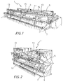
- Fig. 1 is a perspective view of the head member of the invention with the pickup reel lowered, in an open position;
- Fig. 2 is a perspective view of the head member di Fig. 1 with the movable parts folded over the central part;
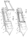
- Fig. 3 is a perspective back view of the head member of Fig. 1 with the access frame detached;
- Fig. 4 is a perspective view, similar to Fig. 3, with the access frame applied;
- Fig. 5 is a perspective view of the head member of the invention, open and with the pickup reel raised;
- Fig. 6 is a schematic perspective view of an embodiment of the reciprocating means of the serrated blade;
- Fig. 7 is a perspective view, similar to Fig. 6, illustrating another embodiment of the reciprocating means for moving the serrated blade;
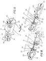
- Fig. 8 is a schematic perspective view illustrating the means for rotating the auger;
- Fig. 9 is a partial perspective view illustrating the retractable tips protruding from the pickup reel, the radial displacement of which is combined with the movement of the auger; and
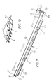
- Fig. 10 is a partial perspective view illustrating the insertion of a blade section within the seats of the teeth cooperating with the blade.
- As shown in the Figures 1, 2 and 5, a cereal harvester head assembly in accordance with the present invention is formed by a head member 1 adapted to be mounted on a harvester (not shown) and comprising an
auger 3, apickup reel 5 that can be raised with respect to theauger 3, and acutting blade 7 inserted and movable between pairs of teeth 9 (Fig. 10). - In said head member 1 the transmission of the motion to the
auger 3, thepickup reel 5 and thecutting blade 7 is provided on one side only of the head assembly 1. - As illustrated in Fig.s 2 and 5, the
pickup reel 5 can be raised with respect to the auger and is adapted to be folded into three parts, i.e. a centralstationary part 11 and twolateral parts 13 that can be moved (i.e. rotated) by means ofcylinders 15 actuated by a pressurized fluid (see Fig. 1). - As better shown in Figures 8 and 9, also the
auger 3 can be folded into three parts, namely a centralstationary part 17 and twolateral parts 19 that can be moved (i.e. rotated) by means ofcylinders 15 actuated by a pressurized fluid.Stationary walls 65 are provided at the ends between theparts auger 3 is eccentric with respect to the rotatory axis of the auger. - As shown in Figures 6, 7 and 10, the
cutting blade 7 is a serrated blade formed by three sections, and more particularly acentral section 21 and twolateral sections 23, driven at the rear and located between pairs ofteeth 9 fastened to a pair of supports similarly divided in three parts. - The transmission of the rotation motion to the
auger 3 is obtained through a motor (not shown in the Figures), coupled to ashaft portion 25 at one end of alateral auger part 19 for rotating saidauger part 19. - At the opposed end of said directly driven
part 19 there are provided a pair ofgears gear 27 being fastened to and coaxial with the drivenlateral part 19 of the auger, while theother gear 29 is fastened to and coaxial with ashaft 31 the axis of which is parallel to but not coincident with the auger rotation axis. As shown in Figure 8, inside theparts 19 there are provided connections comprisingeccentric shafts 63. - The
shaft 31 passes through a hole in thewall 65 ofpart 19 and can axially be coupled through afront clutch 33 or the like with ashaft 35 of the centralstationary part 17, aligned with the former and carrying agear 37 that in turn engages afourth gear 39 fastened to thecentral part 17 of the auger. A similar arrangement is provided between thecentral part 17 and the otherlateral part 19, as illustrated in figure 8. When the threeparts shafts lateral part 19 of the auger to the central and the other lateral sections. When theshafts parts auger 3 are not subjected to any rotation. - The
cutting blade 7 is formed by three elongatedserrated sections motor 41 having a projectingmember 42 reciprocating in the direction of the length of theblade 7. - The means for reciprocating the
blade 7 will now be disclosed with details. - In accordance with a first embodiment illustrated in Figure 6, the means for moving the
blade 7 comprises two groups of alignedrods blade 7, each group comprising three sections or rods, each of the rods of thefirst group 43 being directly fastened to the corresponding section ofblade 7, while each of the rods of thesecond group 45 is connected to the corresponding (laterally adjacent) rod of thefirst group 43 throughtoothed blocks 49 andfixed gears 47. More precisely atoothed block 49 is secured to each rod and agear 47 meshes with the two facing blocks acting as racks. One of the rods of thefirst group 43 is directly coupled to the reciprocatingmember 42. - When a motion along one direction is imparted to the rod of the
first group 43 bymember 42, this motion is transmitted by contact to the subsequent rods of the first group, thus causing the displacement of theserrated blade 7 along the same direction. At the same time, therods 43 of the group directly fastened to the blade transmit the motion - along the opposed direction - to the rods of thesecond group 45 that are brought into a starting position for the return stroke. - Thereafter the inversion of the reciprocating movement imparted to the rod of the
group 43 directly coupled tomember 42 pulls in a contrary direction such rod, and through the members 49-47-49 pushes in the opposed direction the corresponding rods of thesecond group 45. This latter rods will act (push) on the subsequent rods of the second group and in turn each of these rods will move the corresponding rod of thefirst group 43, thus moving as a one-piece member thegroup 43 and therefore theblade 7. This way the blade is returned in the starting position and is ready for a new cycle, and a reciprocating movement of the blade is achieved with a construction that is foldable. - According to a second embodiment illustrated in Figure 7, the reciprocating means for the
blade 7 is partially similar to that of the first embodiment, i.e. comprises three blade sections, a first group of three alignedrods 51 each directly fastened to the corresponding sections ofblade 7, and a second group of three alignedrods 53. According to this embodiment the terminal ends 55 and 57 of the corresponding lateral rods are connected to each other by two rocker arms orcams rocker arm 59 there is connected the shaft of thesecond motor 41 that periodically reverses the direction of rotation in this embodiment. - When the
motor 41 rotated through a first angle in a first direction therocker arm 59 drives thefirst rod 51 and the subsequent aligned rods of the group, and will cause a rotation of thereturn rocker arm 61 at the opposed end, this rotation in turn driving in a similar manner but along the opposed direction therods 53 of the second group. When the motor rotation is reversed, therocker arm 59 applies a push to therod 53 and to the subsequent rods of the aligned group that in turn rotate therocker arm 61, thus causing the return movement of the rods directly connected to the blade, i.e. the return movement of the blade, thus realizing the reciprocating movement of theserrated blade 7. - As better shown in Figures 8 and 9, the three parts of the
auger 3 are formed as hollow cylindrical bodies. Inside these cylindrical bodies there is providedeccentric shafts 63, the axes of which are parallel but not coincident with the central axis of theauger 3. As illustrated in Figure 9 for thecentral part 19, theshaft 63 is fastened at a selectable angle to the fixedwalls 65 that divide the rotating parts of the auger; thiseccentric shaft 63 carries idle T-shapedsleeves 67 on which there are mountedradial pins 69 each having an opposed end protruding through a correspondinghole 71 in the longitudinal wall of the auger part. This way the relative position of theshaft 63 with respect to the auger 3 (that is near or far away) causes the protruding or the retraction of thepins 69 from the wall of the auger when the auger rotates. Thus the rotation of theauger 3 brings such pins to the maximun protrusion when they are in a "high" position, i.e far from the ground, and to a substantially null protrusion when they are going to contact the ground. - From the above it is evident that the subject head assembly comprises members that are foldable into three parts, with a fixed central part and two lateral parts foldable over the central part until they rest thereon, and that the head assembly can be folded into three parts without any interference between the driving and driven components.
Claims (7)
- A cereal head assembly (1) for a combine-harvester machine comprising an auger (3), a pickup reel (5) that can be raised with respect to said auger (3), and a cutting blade (7) located between pairs of teeth (9), characterized in that:a) the motion to the auger (3), the pickup reel (5) and the blade (7) is provided on one side only of said head assembly;b) said pickup reel (5) is adapted to be folded into three parts, i.e. a central stationary part (11) and two lateral parts (13) that can be moved by means of cylinders (15) actuated by a pressurized fluid;c) said auger (3) is adapted to be folded into three parts, i.e. a central stationary part (17) and due lateral parts (19) that can be moved by means of cylinders (15) actuated by a pressurized fluid, with the transmission of the rotation movement being out of center with respect to the rotation axis of said auger (3);d) said blade (7) is formed by three sections, i.e. a central fixed section (21) and two movable lateral sections (23), is driven at the rear and located between said pairs of teeth (9); whereby said head assembly (1) comprises two lateral parts adapted to be folded over and to rest onto a fixed central part.
- A head assembly as claimed in claim 1, characterized in that the transmission of said rotation motion to the auger (3) is accomplished through a first motor mounted at one end (25) of a lateral part (19) of said auger that driving said lateral part (19) of the auger; at the other end of said lateral part (19) being provided a pair of gears (27, 29) meshing with each other, one (27) of said gears being fastened to and coaxial with said lateral part (19) of the auger, while the other gear (29) is fastened to and coaxial with a first shaft (31) the axis of which is parallel to but not coincident with the auger rotation axis; in that a front clutch (33) is provided for axially coupling said first shaft (31) with a second shaft (35) of the central stationary part (17), said second shaft (35) being aligned with said first shaft (31) and carrying a third gear (37) that in turn engages a fourth gear (39) fastened to the central part (17) of the auger, so that when said shafts (31, 35) are coupled to each other, the rotation motion is transmitted by the driven lateral part (19) of the auger to the central part (17) and the other lateral section (19).
- A head assembly as claimed in claim 1 and 2, characterized in that said blade (7) is a serrated blade driven by reciprocating means.
- A head assembly as claimed in claim 3, characterized in that said reciprocating means comprises a second rotating motor (41) having a projecting member (42) reciprocating along the length of the blade (7), and in that said means comprises two groups of aligned rods (43, 45) parallel to each other and to said blade (7), each group comprising three rods, the rods of a first one (43) of said groups of aligned rods being directly connected to said blade (7), and the rods of the second group (45) being connected to those of the first group (43) through devices for transmitting a reciprocating motion between said two groups (Fig. 6).
- A head assembly as claimed in claim 4, characterized in that each of said devices for transmitting the reciprocating motion comprises a fixed gear (47) engaging a pair of toothed blocks (49) acting as racks and provided on two corresponding rods of said groups (43, 45), whereby the movement in one direction imparted to a rod (43) of the said groups (43, 45) connected to the projecting member (42) of the rotating motor (41) is transmitted by contact to the subsequent rods of the same group, thus causing the displacement of the serrated blade (7) in the same direction and the displacement - along the opposed direction - of the rods (45) of the second group; and whereby the inversion of the reciprocating movement imparted to the rod (43) coupled to the reciprocating member (42) pulls in a contrary direction such rod (43), and through said devices for transmitting the reciprocating motion (49, 47, 49) pushes in the opposed direction the corresponding rods of the second group (45).
- A head assembly as claimed in claim 3, characterized in that said reciprocating means comprises two groups of aligned rods (51, 53) parallel to each other and to said blade (7), each group comprising three rods, the rods of a first one (43) of said groups of aligned rods being directly connected to said blade (7), the terminal ends (55, 57) of the corresponding lateral rods being connected to each other by two rocker arms (59, 61), each comprising a short arm pivotally connected with the rods at both ends, and in that at the center of one (59) of said rocker arms there is connected the shaft of a second motor (41) that periodically reverses the direction of rotation. (Fig.7).
- A head assembly as claimed in the preceding claims, characterized in that within said auger (3) formed as a hollow cylindrical body there is provided an eccentric shaft (63), with the axis parallel but not coincident with the central axis of said auger (3), said shaft is fastened at a selectable angle to fixed walls (65) separating the parts of the auger; and in that said eccentric shaft (63) carries idle sleeves (67) on which there are mounted radial pins (69) each having an opposed end protruding through a corresponding hole (71) in the longitudinal wall of the auger (3), so that the relative position of the shaft (63) with respect to the auger (3) causes the protruding or the retraction of said pins (69) from the wall of the auger when the auger rotates whereby the rotation of the auger (3) brings such tips to the maximun protrusion when they are in a "high" position, i.e far from the ground, and to a substantially null protrusion when they are going to contact the ground.
Applications Claiming Priority (2)
| Application Number | Priority Date | Filing Date | Title |
|---|---|---|---|
| IT96TO000102A IT1285240B1 (en) | 1996-02-16 | 1996-02-16 | CEREAL HEAD APPLICABLE TO THE COMBINE HARVESTER |
| ITTO960102 | 1996-02-16 |
Publications (2)
| Publication Number | Publication Date |
|---|---|
| EP0789990A1 true EP0789990A1 (en) | 1997-08-20 |
| EP0789990B1 EP0789990B1 (en) | 2001-04-18 |
Family
ID=11414255
Family Applications (1)
| Application Number | Title | Priority Date | Filing Date |
|---|---|---|---|
| EP97101529A Expired - Lifetime EP0789990B1 (en) | 1996-02-16 | 1997-01-31 | A head assembly for a cereal combine-harvester |
Country Status (4)
| Country | Link |
|---|---|
| EP (1) | EP0789990B1 (en) |
| AT (1) | ATE200605T1 (en) |
| DE (1) | DE69704584T2 (en) |
| IT (1) | IT1285240B1 (en) |
Cited By (13)
| Publication number | Priority date | Publication date | Assignee | Title |
|---|---|---|---|---|
| EP1021944A1 (en) | 1999-01-21 | 2000-07-26 | Capello F.Lli Renato E Francesco S.N.C. | Foldable head for combine |
| EP1632124A1 (en) | 2004-09-07 | 2006-03-08 | CLAAS Selbstfahrende Erntemaschinen GmbH | Cutting device for harvester |
| DE102004059038A1 (en) * | 2004-12-07 | 2006-07-06 | Maschinenfabrik Kemper Gmbh & Co. Kg | Harvest machine, harvesting trailer and wagon combination e.g. field chopper, for harvesting e.g. corn, has frame designed to directly trigger support force, which is exerted by wagon when driven on road, on support frame in mounted state |
| US7165384B1 (en) | 2005-12-13 | 2007-01-23 | Maschinenfabrik Kemper Gmbh & Co Kg | Crop picking head with road travel support device |
| US7614206B2 (en) | 2007-06-04 | 2009-11-10 | Claas Selbstfahrende Erntemaschinen Gmbh | Winged header apparatus and method for a combine |
| DE102008040217A1 (en) | 2008-07-07 | 2010-01-14 | Maschinenfabrik Kemper Gmbh & Co. Kg | Harvesting attachment e.g. pick-up, for field chopper, has outer parts with transverse conveyor elements provided in area in transporting position, at which transverse conveyor element of middle part is provided at operating position |
| US9795083B2 (en) | 2014-09-10 | 2017-10-24 | Cnh Industrial America Llc | Vertically and rotatably moveable header wing |
| US9992924B2 (en) | 2015-03-13 | 2018-06-12 | Cnh Industrial America Llc | Folding mechanism for wide wheat headers |
| US9999178B2 (en) | 2015-06-12 | 2018-06-19 | Oxbo International Corporation | Cam for a windrow merger and pickup head having a variable radius |
| IT201600131283A1 (en) * | 2016-12-27 | 2018-06-27 | Capello S R L | Harvesting head for a cereal harvesting machine |
| US10433483B2 (en) | 2017-08-21 | 2019-10-08 | Cnh Industrial America Llc | Agricultural header with one or more movable wing sections |
| WO2020154644A1 (en) * | 2019-01-24 | 2020-07-30 | Cnh Industrial America Llc | Reel assembly of an agricultural header |
| CN113228923A (en) * | 2021-06-28 | 2021-08-10 | 安徽云龙粮机有限公司 | Soybean harvesting and threshing integrated machine and control method thereof |
Families Citing this family (1)
| Publication number | Priority date | Publication date | Assignee | Title |
|---|---|---|---|---|
| DE19918551B4 (en) † | 1999-04-23 | 2015-04-02 | Deere & Company | harvester |
Citations (8)
| Publication number | Priority date | Publication date | Assignee | Title |
|---|---|---|---|---|
| DE2026190A1 (en) * | 1969-06-02 | 1970-12-23 | Clayson naamloze vennootschap, Zedelgem (Belgien) | Divisible cutting board for combine harvesters |
| GB2055539A (en) * | 1979-08-04 | 1981-03-11 | Deere & Co | Reciprocating mower |
| EP0131853A1 (en) * | 1983-07-07 | 1985-01-23 | Carl Geringhoff GmbH & Co KG | Maize harvester |
| DE8535733U1 (en) * | 1985-12-19 | 1986-02-06 | Carl Geringhoff GmbH & Co KG, 4730 Ahlen | Coupling for auger parts of a corn harvester |
| US4910946A (en) * | 1988-06-20 | 1990-03-27 | Probe Adventures, Inc. | Extensible combine header |
| EP0373406A1 (en) * | 1988-12-16 | 1990-06-20 | Claas Ohg | Self-propelled combine harvester with a divided cutting device |
| EP0491405A1 (en) * | 1990-12-18 | 1992-06-24 | Capello F.Lli Renato E Francesco S.N.C. | A foldable head for a maize picker machine |
| EP0634088A1 (en) * | 1993-07-13 | 1995-01-18 | CLAAS Kommanditgesellschaft auf Aktien | Combine |
-
1996
- 1996-02-16 IT IT96TO000102A patent/IT1285240B1/en active IP Right Grant
-
1997
- 1997-01-31 EP EP97101529A patent/EP0789990B1/en not_active Expired - Lifetime
- 1997-01-31 DE DE69704584T patent/DE69704584T2/en not_active Expired - Lifetime
- 1997-01-31 AT AT97101529T patent/ATE200605T1/en not_active IP Right Cessation
Patent Citations (8)
| Publication number | Priority date | Publication date | Assignee | Title |
|---|---|---|---|---|
| DE2026190A1 (en) * | 1969-06-02 | 1970-12-23 | Clayson naamloze vennootschap, Zedelgem (Belgien) | Divisible cutting board for combine harvesters |
| GB2055539A (en) * | 1979-08-04 | 1981-03-11 | Deere & Co | Reciprocating mower |
| EP0131853A1 (en) * | 1983-07-07 | 1985-01-23 | Carl Geringhoff GmbH & Co KG | Maize harvester |
| DE8535733U1 (en) * | 1985-12-19 | 1986-02-06 | Carl Geringhoff GmbH & Co KG, 4730 Ahlen | Coupling for auger parts of a corn harvester |
| US4910946A (en) * | 1988-06-20 | 1990-03-27 | Probe Adventures, Inc. | Extensible combine header |
| EP0373406A1 (en) * | 1988-12-16 | 1990-06-20 | Claas Ohg | Self-propelled combine harvester with a divided cutting device |
| EP0491405A1 (en) * | 1990-12-18 | 1992-06-24 | Capello F.Lli Renato E Francesco S.N.C. | A foldable head for a maize picker machine |
| EP0634088A1 (en) * | 1993-07-13 | 1995-01-18 | CLAAS Kommanditgesellschaft auf Aktien | Combine |
Cited By (24)
| Publication number | Priority date | Publication date | Assignee | Title |
|---|---|---|---|---|
| EP1021944A1 (en) | 1999-01-21 | 2000-07-26 | Capello F.Lli Renato E Francesco S.N.C. | Foldable head for combine |
| EP1632124A1 (en) | 2004-09-07 | 2006-03-08 | CLAAS Selbstfahrende Erntemaschinen GmbH | Cutting device for harvester |
| DE102004059038A1 (en) * | 2004-12-07 | 2006-07-06 | Maschinenfabrik Kemper Gmbh & Co. Kg | Harvest machine, harvesting trailer and wagon combination e.g. field chopper, for harvesting e.g. corn, has frame designed to directly trigger support force, which is exerted by wagon when driven on road, on support frame in mounted state |
| DE102004059038B4 (en) * | 2004-12-07 | 2006-09-28 | Maschinenfabrik Kemper Gmbh & Co. Kg | Combination of a harvester, a header and a trolley to support the header |
| US7165384B1 (en) | 2005-12-13 | 2007-01-23 | Maschinenfabrik Kemper Gmbh & Co Kg | Crop picking head with road travel support device |
| US7614206B2 (en) | 2007-06-04 | 2009-11-10 | Claas Selbstfahrende Erntemaschinen Gmbh | Winged header apparatus and method for a combine |
| DE102008040217A1 (en) | 2008-07-07 | 2010-01-14 | Maschinenfabrik Kemper Gmbh & Co. Kg | Harvesting attachment e.g. pick-up, for field chopper, has outer parts with transverse conveyor elements provided in area in transporting position, at which transverse conveyor element of middle part is provided at operating position |
| DE102008040217B4 (en) * | 2008-07-07 | 2015-01-15 | Maschinenfabrik Kemper Gmbh & Co. Kg | Between an operating position and a compact transport position adjustable header |
| US9795083B2 (en) | 2014-09-10 | 2017-10-24 | Cnh Industrial America Llc | Vertically and rotatably moveable header wing |
| US9992924B2 (en) | 2015-03-13 | 2018-06-12 | Cnh Industrial America Llc | Folding mechanism for wide wheat headers |
| US9999178B2 (en) | 2015-06-12 | 2018-06-19 | Oxbo International Corporation | Cam for a windrow merger and pickup head having a variable radius |
| WO2018122744A1 (en) * | 2016-12-27 | 2018-07-05 | Capello S.R.L. | Harvesting header for a grain harvesting machine |
| IT201600131283A1 (en) * | 2016-12-27 | 2018-06-27 | Capello S R L | Harvesting head for a cereal harvesting machine |
| CN110099560A (en) * | 2016-12-27 | 2019-08-06 | 卡佩罗公司 | Harvesting head for corn mowing machine |
| US20190335663A1 (en) * | 2016-12-27 | 2019-11-07 | Capello S.R.L. | Harvesting header for a grain harvesting machine |
| CN110099560B (en) * | 2016-12-27 | 2020-03-27 | 卡佩罗公司 | Harvesting head for grain harvester |
| US10743466B2 (en) | 2016-12-27 | 2020-08-18 | Capello S.R.L. | Harvesting header for a grain harvesting machine |
| RU2745928C2 (en) * | 2016-12-27 | 2021-04-05 | Капелло С.Р.Л. | Grain header for grain harvesting machine |
| US10433483B2 (en) | 2017-08-21 | 2019-10-08 | Cnh Industrial America Llc | Agricultural header with one or more movable wing sections |
| US11224165B2 (en) | 2017-08-21 | 2022-01-18 | Cnh Industrial America Llc | Agricultural header with one or more movable wing sections |
| US11930739B2 (en) | 2017-08-21 | 2024-03-19 | Cnh Industrial America Llc | Agricultural header with one or more movable wing sections |
| WO2020154644A1 (en) * | 2019-01-24 | 2020-07-30 | Cnh Industrial America Llc | Reel assembly of an agricultural header |
| US12058959B2 (en) | 2019-01-24 | 2024-08-13 | Cnh Industrial America Llc | Reel assembly of an agricultural header |
| CN113228923A (en) * | 2021-06-28 | 2021-08-10 | 安徽云龙粮机有限公司 | Soybean harvesting and threshing integrated machine and control method thereof |
Also Published As
| Publication number | Publication date |
|---|---|
| ITTO960102A0 (en) | 1996-02-16 |
| DE69704584T2 (en) | 2001-11-08 |
| IT1285240B1 (en) | 1998-06-03 |
| ATE200605T1 (en) | 2001-05-15 |
| ITTO960102A1 (en) | 1997-08-16 |
| DE69704584D1 (en) | 2001-05-23 |
| EP0789990B1 (en) | 2001-04-18 |
Similar Documents
| Publication | Publication Date | Title |
|---|---|---|
| EP0789990B1 (en) | A head assembly for a cereal combine-harvester | |
| DE102008031261B4 (en) | Wiper system for a vehicle | |
| EP3278655B1 (en) | Portable beating device for picking fruit off trees, in particular for picking olives | |
| EP0424834B1 (en) | Windshield wiper apparatus for vehicle | |
| GB1275492A (en) | Improvements in or relating to harvesting machines | |
| JPH04248912A (en) | Reciprocating saw blade device | |
| US6629442B2 (en) | Cutting blade bending apparatus capable of precisely forming acute angle | |
| DE69303845T2 (en) | Device for erecting containers from a position with a horizontal axis to a position with a vertical axis | |
| DD150182A5 (en) | MACHINE FOR WRAPPING AND GROUPING PRODUCTS | |
| DE19642014B4 (en) | Device for packing small-sized articles in the fold wrapping | |
| DE2024022A1 (en) | Motor unit for driving horticulture or agricultural machinery or tools | |
| EP0094521B1 (en) | Automobile window wiping device | |
| DE102018123213B4 (en) | Robot with a fixing element that can be locked in different positions to change the size of the work area, and method for changing the work area of a robot. | |
| DE10032098C2 (en) | robot arm | |
| JP2001287187A (en) | Transfer device | |
| DE4332683A1 (en) | Device for the drive of a swinging pre-gripper for individual-sheet transportation in a printing machine | |
| JP4004371B2 (en) | Combine | |
| WO1990000993A1 (en) | A windscreen wiper installation, especially for motor vehicles | |
| JPH05253855A (en) | Intermittent feed mechanism and bolt / nut attaching / detaching device using the same | |
| US5848745A (en) | Stitching device | |
| JPH02214446A (en) | Coil winding machine for stator core | |
| CN210248057U (en) | Encircling telescopic winding device | |
| EP0319488A1 (en) | A windscreen wiper device for motor vehicles | |
| EP0836993A1 (en) | A method and a unit for carton-wrapping packets of cigarettes | |
| JP3861494B2 (en) | Work payout device |
Legal Events
| Date | Code | Title | Description |
|---|---|---|---|
| PUAI | Public reference made under article 153(3) epc to a published international application that has entered the european phase |
Free format text: ORIGINAL CODE: 0009012 |
|
| AK | Designated contracting states |
Kind code of ref document: A1 Designated state(s): AT DE ES FR GB IT NL |
|
| 17P | Request for examination filed |
Effective date: 19971124 |
|
| GRAG | Despatch of communication of intention to grant |
Free format text: ORIGINAL CODE: EPIDOS AGRA |
|
| 17Q | First examination report despatched |
Effective date: 20000322 |
|
| GRAG | Despatch of communication of intention to grant |
Free format text: ORIGINAL CODE: EPIDOS AGRA |
|
| GRAH | Despatch of communication of intention to grant a patent |
Free format text: ORIGINAL CODE: EPIDOS IGRA |
|
| GRAH | Despatch of communication of intention to grant a patent |
Free format text: ORIGINAL CODE: EPIDOS IGRA |
|
| GRAA | (expected) grant |
Free format text: ORIGINAL CODE: 0009210 |
|
| ITF | It: translation for a ep patent filed | ||
| AK | Designated contracting states |
Kind code of ref document: B1 Designated state(s): AT DE ES FR GB IT NL |
|
| PG25 | Lapsed in a contracting state [announced via postgrant information from national office to epo] |
Ref country code: NL Free format text: LAPSE BECAUSE OF FAILURE TO SUBMIT A TRANSLATION OF THE DESCRIPTION OR TO PAY THE FEE WITHIN THE PRESCRIBED TIME-LIMIT Effective date: 20010418 Ref country code: AT Free format text: LAPSE BECAUSE OF FAILURE TO SUBMIT A TRANSLATION OF THE DESCRIPTION OR TO PAY THE FEE WITHIN THE PRESCRIBED TIME-LIMIT Effective date: 20010418 |
|
| REF | Corresponds to: |
Ref document number: 200605 Country of ref document: AT Date of ref document: 20010515 Kind code of ref document: T |
|
| REF | Corresponds to: |
Ref document number: 69704584 Country of ref document: DE Date of ref document: 20010523 |
|
| ET | Fr: translation filed | ||
| NLV1 | Nl: lapsed or annulled due to failure to fulfill the requirements of art. 29p and 29m of the patents act | ||
| PG25 | Lapsed in a contracting state [announced via postgrant information from national office to epo] |
Ref country code: ES Free format text: LAPSE BECAUSE OF FAILURE TO SUBMIT A TRANSLATION OF THE DESCRIPTION OR TO PAY THE FEE WITHIN THE PRESCRIBED TIME-LIMIT Effective date: 20011030 |
|
| REG | Reference to a national code |
Ref country code: GB Ref legal event code: IF02 |
|
| PG25 | Lapsed in a contracting state [announced via postgrant information from national office to epo] |
Ref country code: GB Free format text: LAPSE BECAUSE OF NON-PAYMENT OF DUE FEES Effective date: 20020131 |
|
| PLBE | No opposition filed within time limit |
Free format text: ORIGINAL CODE: 0009261 |
|
| STAA | Information on the status of an ep patent application or granted ep patent |
Free format text: STATUS: NO OPPOSITION FILED WITHIN TIME LIMIT |
|
| 26N | No opposition filed | ||
| GBPC | Gb: european patent ceased through non-payment of renewal fee |
Effective date: 20020131 |
|
| PG25 | Lapsed in a contracting state [announced via postgrant information from national office to epo] |
Ref country code: IT Free format text: LAPSE BECAUSE OF NON-PAYMENT OF DUE FEES Effective date: 20100131 |
|
| PGRI | Patent reinstated in contracting state [announced from national office to epo] |
Ref country code: IT Effective date: 20110616 |
|
| REG | Reference to a national code |
Ref country code: FR Ref legal event code: PLFP Year of fee payment: 20 |
|
| PGFP | Annual fee paid to national office [announced via postgrant information from national office to epo] |
Ref country code: IT Payment date: 20160118 Year of fee payment: 20 Ref country code: DE Payment date: 20160229 Year of fee payment: 20 |
|
| PGFP | Annual fee paid to national office [announced via postgrant information from national office to epo] |
Ref country code: FR Payment date: 20160405 Year of fee payment: 20 |
|
| REG | Reference to a national code |
Ref country code: DE Ref legal event code: R071 Ref document number: 69704584 Country of ref document: DE |