EP0789836B1 - Vorrichtung und verfahren zur detektion eines lecks in einem verdampfungsemissionssteuerungssystem - Google Patents
Vorrichtung und verfahren zur detektion eines lecks in einem verdampfungsemissionssteuerungssystem Download PDFInfo
- Publication number
- EP0789836B1 EP0789836B1 EP96918472A EP96918472A EP0789836B1 EP 0789836 B1 EP0789836 B1 EP 0789836B1 EP 96918472 A EP96918472 A EP 96918472A EP 96918472 A EP96918472 A EP 96918472A EP 0789836 B1 EP0789836 B1 EP 0789836B1
- Authority
- EP
- European Patent Office
- Prior art keywords
- flow
- leak
- fuel tank
- atmosphere
- pressure difference
- Prior art date
- Legal status (The legal status is an assumption and is not a legal conclusion. Google has not performed a legal analysis and makes no representation as to the accuracy of the status listed.)
- Expired - Lifetime
Links
Images

Classifications
-
- F—MECHANICAL ENGINEERING; LIGHTING; HEATING; WEAPONS; BLASTING
- F02—COMBUSTION ENGINES; HOT-GAS OR COMBUSTION-PRODUCT ENGINE PLANTS
- F02M—SUPPLYING COMBUSTION ENGINES IN GENERAL WITH COMBUSTIBLE MIXTURES OR CONSTITUENTS THEREOF
- F02M25/00—Engine-pertinent apparatus for adding non-fuel substances or small quantities of secondary fuel to combustion-air, main fuel or fuel-air mixture
- F02M25/08—Engine-pertinent apparatus for adding non-fuel substances or small quantities of secondary fuel to combustion-air, main fuel or fuel-air mixture adding fuel vapours drawn from engine fuel reservoir
- F02M25/0809—Judging failure of purge control system
Definitions
- This invention is generally directed to the field of vehicular emissions control and in particular to detection of leaks in an evaporative emissions system.
- Contemporary vehicles including passenger cars, light duty trucks, and medium duty vehicles use evaporative emissions systems to prevent unnecessary emission of hydrocarbon (HC) vapors into the atmosphere.
- HC hydrocarbon
- These emissions are primarily composed of gasoline vapors leaking from a vehicle's fuel tank to the air.
- the fuel tank is periodically vented into a canister filled with charcoal that filters the HC vapors and releases the filtered air to the atmosphere.
- the charcoal traps the hydrocarbon molecules from the polluting vapors, preventing them from leaking to the atmosphere.
- Near term regulation requires the monitoring of the vehicle's evaporative emission system to ensure integrity of operation. This requirement specifies, among other things, checking of the absence of leaks in the system. More specifically, the California Air Resources Board, CARB, specifies in their proposed On Board Diagnostic II, or OBD II, requirement to check the evaporative emissions system for leaks. This requires detecting system leaks equivalent to an orifice larger than 0.020 inches in diameter for vehicles produced in model year 2000.
- a prior art scheme for detecting leaks measures a re-pressurization time.
- DP 10 inches of water
- the amount of space above the fuel varies with fuel level, and the corresponding change in fuel tank volume causes the re-pressurization time to vary as a function of fuel level.
- inaccuracies can be caused by fuel evaporation during the leak test.
- fuel evaporation With high volatility (winter) fuel, on a warm day fuel evaporation generates vapor at a rate that exceeds the amount of gas flow generated by 10 inches of water across a 0.020 inch hole. This can cause false leak detection on warm days when the fuel tank contains high volatility fuel.
- the 10 inches of water vacuum drawn on the fuel tank during the test causes the fuel tank to flex. This causes the fuel tank to hold vacuum for a longer period of time during re-pressurization.
- Another prior art scheme uses a positive displacement pump to pressurize the fuel tank with air and measure the air flow with the fuel tank pressurized. Safety is at issue here because the air pumped into the fuel tank may cause an explosion hazard. This scheme is subject to the same problems with high volatility fuel on warm days as other prior art schemes and has the potential of increasing HC emissions during a test of a leaky system.
- a apparatus and method of detecting a leak in an evaporative emissions system measures vapor flow out of the evaporative emissions system while maintaining a zero pressure difference from inside a fuel tank to atmosphere and provides a reference vapor flow variable dependent on the vapor flow measurement. Then, a pressurized vapor and leak flow variable is measured dependent on measured vapor flow out of the evaporative emissions system while maintaining a pressure difference of 10" of water from inside the fuel tank to atmosphere.
- a leak is indicated if a difference between the reference vapor flow variable and the pressurized vapor and leak flow variable is greater than a predetermined leak flow factor.
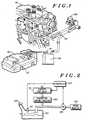
- FIG. 1 is a schematic diagram of a reciprocating engine with an evaporative emissions system.
- An engine 101 is fueled from fuel residing in a fuel tank 103. Because some of the fuel in the fuel tank 103 is in gaseous form it periodically needs to be vented to prevent a dangerous buildup of pressure. While controlling any excessive pressure buildup in the fuel tank 103 it is also vital not to emit hydrocarbons, HCs, to the atmosphere.
- the fuel tank 103 pressure can be vented using an evaporative emissions system as illustrated here.
- the fuel tank 103 is vented through the evaporative. capture canister 105.
- the captured fuel vapor in the evaporative capture canister 105 is inducted into the engine 101 and burned. Burning the captured fuel vapor is done by inducting the vapor in the evaporative capture canister 105 into the intake manifold 107 of the engine 101 via a flow regulation valve 109.
- a flow rate in the system is measured while a DP across the fuel tank is zero.
- DP is a differential pressure measured comparing the atmospheric pressure outside the fuel tank with a pressure inside the fuel tank. The measured flow rate is indicative of a vapor generation rate only. Because the DP across the tank in zero, there is no flow through any leaks in the tank.
- the next step is to measure the flow rate at another DP across the tank. This is done by pulling the vacuum on the fuel tank using the engine.
- FIG. 2 is a schematic representation of the evaporative emission system introduced in FIG. 1.
- a controller 203 is used to operate certain elements.
- the controller 203 is constructed using a Motorola 68HC705B6 microcontroller.
- the Motorola 68HC705B6 microcontroller includes on-board program memory in the form of EPROM (Erasable Programmable Read Only Memory), and an analog to digital converter to interpret a pressure signal from a DP sensor 113.
- EPROM Erasable Programmable Read Only Memory
- This type of controller 203 is easily constructed by those skilled in the art.
- FIG. 3 a flow chart is presented that symbolically describes the various method steps encoded into the controller's program memory.
- the controller 203 is connected to the flow regulation valve 109 for coupling the intake manifold 107 to the fuel system, and for measuring the flow generated by the fuel tank 103.
- the controller 203 also manages the canister vent valve 111, and measures the DP across the fuel tank 103 via the DP sensor 113.
- the leak test is essentially broken into three major sections, a fuel cap test, a fuel state test, and a small leak test.
- the method steps associated with these three major sections are encoded into the controller 203 of FIG. 2 and are executed whenever the leak test is invoked.
- the first is entitled the fuel cap test.
- This test is a gate to the other two tests in FIG. 3 and essentially checks to see if a fuel cap 205 in FIG. 2 is on the fuel tank 103. If the fuel cap 205 is on the fuel tank 103, the next test is to determine a state of the fuel.
- the fuel state test is a vapor generation test. A rate of vapor generation is related to a temperature and volatility of the fuel.
- a small leak test which searches for a small leak in the fuel tank.
- step 307 the flow regulation valve 109 is closed by the controller 203. Closure of the flow regulation valve 109 cuts off any path for vapor flow into the intake manifold 107 of the engine.
- step 309 the controller checks to see if the pressure indicated by the DP sensor 113 is increasing. This checking is typically done over three or four seconds. If there is any vapor generation, the pressure indicated by the DP sensor 113 will increase measurably. If the DP measurement is increasing, there is a pressure build up in the fuel tank and it is inferred that the fuel cap 205 is intact. If in step 309 it is determined that the signal generated by the DP sensor 113 is not increasing, it can't be said for sure that the fuel cap 205 is on or off and further tests are executed.
- step 311 The next portion of the fuel cap test, step 311, is executed by opening the flow regulation valve 109 to attempt to draw a vacuum on the fuel tank 103 using the engine 101 via the intake manifold 107.
- step 313 the output signal of the DP sensor 113 is monitored and checked to see if DP is decreasing. If DP is decreasing, it is likely that there are no large leaks and the fuel state test is initiated. If DP is not decreasing, then the fuel cap 205 is assumed to be off or a large leak is present. If it is determined that the fuel cap 205 is off then step 327 is executed and the routine 300 is exited at step 329.
- a first step 315 in the fuel state test is to regulate the DP in the fuel tank 103 to a first pressure - here zero inches of water using the flow regulation valve 109.
- step 317 vapor flow is measured using the flow regulation valve 109, and reference flow variable VR is provided based on the vapor flow measurement.
- a flow correction factor may optionally be applied depending on the reference flow variable. This adjusts for the slight increase in vapor generation when the tank pressure is lowered.
- the correction factor is derived empirically and may be a function of the reference variable.
- step 321 the fuel tank DP is regulated down to a second pressure - here 10 inches of water below atmospheric pressure using the flow control measurement device 103.
- step 323 the vapor flow is again measured and a pressurized flow variable VP is provided based on the vapor flow measurement.
- step 325 if VP - VR - CF indicates flow due to a leak greater than the OBD II specification, then a leak is indicated in step 327. If VP - VR - CF is not greater than the OBD II specification, then a leak is not indicated and the routine is exited at step 329. Step 325 essentially swamps out the effect of vapor flow on the small leak test. This is a significant departure from prior art approaches and enables a more accurate and reliable leak test in an evaporative emissions system.
- the steps above measure flow for a relatively short period of time typically 15 seconds. During this time the vapor flow is relatively constant, but certain factors may cause the vapor flow to fluctuate. Statistical processing or filtering can be used to account for these fluctuations.
- vehicle motion agitating the fuel and fuel tank flex cause fluctuations. The vehicle motion agitates the fuel, which causes increased vapor generation. This results in abnormally high vapor generation for a short period of time.
- Fuel tank flex causes a transient flow into or out of the fuel tank unrelated to leaks. A lowpass filter or median filter can be used to reject these transients.
- the tests shown in FIG. 3 are preferably aborted if a significant amount of fuel slosh is detected to minimize inaccuracies.
- Fuel slosh can be caused by the vehicle traversing across a rough road. Fuel slosh can be measured using the DP sensor 113. Preferably, a standard deviation of regularly measured DP measurements is used to determine fuel sloshing behavior.
- the above-described approach overcomes problems with varying vapor generation due to fuel volatility and temperature by measuring vapor generation in the absence of leak flow and subtracting this effect from a subsequent measurement of leak flow.
- the time to run the test is independent of the fuel level, fuel volatility, fuel temperature and leak size.
- the new method is also immune to errors caused by changes in fuel level because the flow rate due to vapor generation or due to a leak is unchanged by the amount of space above the fuel in the tank. Also, because the new monitor measures flow at a fixed vacuum, fuel tank flex is also constant and does not change the flow measurement.
- the invention consists of the three steps enumerated above followed by filtering or statistical processing the resulting signal to remove unwanted transient noise.
- the fuel state measurement may be of value to the engine's air-fuel ratio control system.
- the above-described approach offers significantly better accuracy than prior art systems because it accounts for variations in fuel vapor generation rate due to changes in fuel volatility and fuel temperature. This approach also accounts for changes in the vapor space above the liquid fuel in the fuel tank that cause errors in the prior art repressurization type systems. The described approach is safer and more accurate than prior art approaches.
Landscapes
- Engineering & Computer Science (AREA)
- Chemical & Material Sciences (AREA)
- Combustion & Propulsion (AREA)
- Mechanical Engineering (AREA)
- General Engineering & Computer Science (AREA)
- Supplying Secondary Fuel Or The Like To Fuel, Air Or Fuel-Air Mixtures (AREA)
Claims (10)
- Ein Verfahren zur Detektion eines Lecks in einem Verdampfungsemissionssystem für ein Fahrzeug, und das Verfahren die folgenden Schritte aufweist:Messung von Dampfdurchfluss aus dem Verdampfungsemissionssystem heraus, wobei eine erste Druckdifferenz zwischen dem Inneren eines Kraftstofftanks und der Atmosphäre aufrecht erhalten wird, und Bereitstellung einer Bezugsdampfdurchflussvariable, die von der Messung abhängig ist;Messung von Dampfdurchfluss aus dem Verdampfungsemissionssystem heraus, wobei eine andere Druckdifferenz zwischen dem Inneren des Kraftstofftanks und der Atmosphäre aufrecht erhalten wird, und Bereitstellung einer Dampf- und Leckdurchflussvariable unter Druck, die von der Messung abhängig ist;Anzeige eines Lecks, falls eine Differenz zwischen der Bezugsdampfdurchflussvariable und der Dampf- und Leckdurchflussvariable unter Druck größer ist als ein vorherbestimmter Leckflussfaktor.
- Ein Verfahren in Übereinstimmung mit Anspruch 1, bei dem die Schritte zum Aufrechthalten einer Druckdifferenz zwischen der Atmosphäre und dem Kraftstofftank weiter die folgenden Schritte aufweisen:Berechnung einer Standardabweichung der Druckdifferenz zwischen der Atmosphäre und dem Kraftstofftank; undAbbrechen der übrigen Schritte, falls die berechnete Standardabweichung einen vorherbestimmten Schwellwert übersteigt.
- Ein Verfahren zur Detektion eines Lecks in einem Verdampfungsemissionssystem für ein Fahrzeug, und das Verfahren die folgenden Schritte aufweist:Schließen eines Belüftungsventils des Verdampfungsauffangkanisters, das zwischen dem Kraftstofftank und der Atmosphäre angeordnet ist;Regulierung einer Druckdifferenz zwischen der Atmosphäre und dem Kraftstofftank auf 0 cm Wassersäule durch Steuerung eines Durchflussregelventils, das zwischen dem Kraftstofftank und der Eingangssammelleitung der Maschine angeordnet ist;Messung von Dampfdurchfluss unter Verwendung des Durchflussregelventils und Bereitstellung einer Bezugsdampfdurchflussvariable;Bestimmung eines Flusskorrekturfaktors, der abhängig ist von der Bezugsdampfdurchflussvariable für eine Druckdifferenz zwischen der Atmosphäre und dem Kraftstofftank von 25,4 cm Wassersäule;Regulierung einer Druckdifferenz zwischen der Atmosphäre und dem Kraftstofftank auf 25,4 cm Wassersäule durch Steuerung eines Durchflussregelventils;Messung von Dampfdurchfluss unter Verwendung des Durchflussregelventils und Bereitstellung einer Durchflussvariable unter Druck; undAnzeige eines Lecks, abhängig von der Bezugsdampfdurchflussvariable, dem Flusskorrekturfaktor und der Durchflussvariable unter Druck.
- Ein Verfahren in Übereinstimmung mit Anspruch 3, bei dem der Schritt zum Anzeigen eines Lecks die folgenden Schritte aufweist:Bestimmung einer Leckflussvariable, die abhängig ist von einer Differenz zwischen der Durchflussvariable unter Druck und sowohl der Bezugsdampfdurchflussvariable als auch dem Flusskorrekturfaktor; undAnzeige des Lecks, falls die Leckflussvariable einen vorherbestimmten Schwellwert übersteigt.
- Ein Verfahren in Übereinstimmung mit Anspruch 3, bei dem der Schritt zum Einregeln einer Druckdifferenz zwischen der Atmosphäre und dem Kraftstofftank weiter die folgenden Schritte aufweist:Berechnung einer Standardabweichung der Druckdifferenz zwischen der Atmosphäre und dem Kraftstofftank; undAbbrechen der übrigen Schritte, falls die berechnete Standardabweichung einen vorherbestimmten Schwellwert übersteigt.
- Eine Vorrichtung zur Detektion eines Lecks in einem Verdampfungsemissionssystem für ein Fahrzeug, und die Vorrichtung das Folgende aufweist:Ein Durchflussregelventil zur Messung von Dampfdurchfluss heraus aus dem Verdampfungsemissionssystem, wobei eine erste Druckdifferenz zwischen dem Inneren des Kraftstofftanks und der Atmosphäre aufrecht erhalten wird, und zur Bereitstellung einer Bezugsdampfdurchflussvariable, die von der Messung abhängig ist, und das Durchflussregelventil zur Messung von Dampfdurchfluss aus dem Verdamp fungsemissionssystem heraus, wobei eine zweite Druckdifferenz zwischen dem Inneren des Kraftstofftanks und der Atmosphäre aufrecht erhalten wird, und zur Bereitstellung einer Dampf- und Leckdurchflussvariable unter Druck, die von der Messung abhängig ist;eine Steuerung zur Anzeige eines Lecks, falls die Differenz zwischen der Bezugsdampfdurchflussvariable und der Dampf- und Leckdurchflussvariable unter Druck größer ist als ein vorherbestimmter Leckflussfaktor.
- Eine Vorrichtung in Übereinstimmung mit Anspruch 6, bei der die Steuerung weiter aufweist:Mittel zur Berechnung einer Standardabweichung der Druckdifferenz zwischen der Atmosphäre und dem Kraftstofftank; undAbbruch der Leckanzeige, falls die berechnete Standardabweichung einen vorherbestimmten Schwellwert übersteigt.
- Eine Vorrichtung zur Detektion eines Lecks in einem Verdampfungsemissionssystem für ein Fahrzeug, und die Vorrichtung aufweist:Mittel zum Schließen eines Belüftungsventils des Verdampfungsauffangkanisters, das zwischen einem Kraftstofftank und der Atmosphäre angeordnet ist;Mittel zur Regulierung einer Druckdifferenz zwischen der Atmosphäre und dem Kraftstofftank auf 0 cm Wassersäule durch Steuerung eines Durchflussregelventils, das zwischen dem Kraftstofftank und einer Eingangssammelleitung der Maschine angeordnet ist;Mittel zur Messung von Dampfdurchfluss unter Verwendung des Durchflussregelventils und zur Bereitstellung einer Bezugsdampfdurchflussvariable;Mittel zur Bestimmung eines Flusskorrekturfaktors, der abhängig ist von der Bezugsdampfdurchflussvariable für eine Druckdifferenz zwischen der Atmosphäre und dem Kraftstofftank von 25,4 cm Wassersäule;Mittel zur Regulierung einer Druckdifferenz zwischen der Atmosphäre und dem Kraftstofftank auf 25,4 cm Wassersäule durch Steuerung eines Durchflussregelventils;Mittel zur Messung von Dampfdurchfluss unter Verwendung des Durchflussregelventils und zur Bereitstellung einer Dampfdurchflussvariable unter Druck; undMittel zur Anzeige eines Lecks, die abhängig sind von der Bezugsdampfdurchflussvariable, dem Flusskorrekturfaktor und der Dampfdurchflussvariable unter Druck.
- Eine Vorrichtung in Übereinstimmung mit Anspruch 8, bei der die Mittel zur Anzeige eines Lecks weiter aufweisen:Mittel zur Bestimmung einer Leckflussvariable, die abhängig ist von einer Differenz zwischen der Dampfdurchflussvariable unter Druck und sowohl der Bezugsdampfdurchflussvariable als auch des Flusskorrekturfaktors; undbei der die Mittel zur Anzeige des Lecks ein Leck anzeigen, falls die Leckflussvariable einen vorherbestimmten Schwellwert übersteigt.
- Eine Vorrichtung in Übereinstimmung mit Anspruch 9, bei der die Steuerung weiter aufweist:Mittel zur Berechnung einer Standardabweichung der Druckdifferenz zwischen der Atmosphäre und dem Kraftstofftank; undAbbruch der Leckanzeige, falls die berechnete Standardabweichung einen vorherbestimmten Schwellwert übersteigt.
Applications Claiming Priority (3)
| Application Number | Priority Date | Filing Date | Title |
|---|---|---|---|
| US511331 | 1995-08-03 | ||
| US08/511,331 US5637788A (en) | 1995-08-03 | 1995-08-03 | Apparatus and method of detecting a leak in an evaporative emissions system |
| PCT/US1996/010131 WO1997006421A1 (en) | 1995-08-03 | 1996-06-12 | Apparatus and method of detecting a leak in an evaporative emissions system |
Publications (3)
| Publication Number | Publication Date |
|---|---|
| EP0789836A1 EP0789836A1 (de) | 1997-08-20 |
| EP0789836A4 EP0789836A4 (de) | 1998-12-16 |
| EP0789836B1 true EP0789836B1 (de) | 2001-10-24 |
Family
ID=24034432
Family Applications (1)
| Application Number | Title | Priority Date | Filing Date |
|---|---|---|---|
| EP96918472A Expired - Lifetime EP0789836B1 (de) | 1995-08-03 | 1996-06-12 | Vorrichtung und verfahren zur detektion eines lecks in einem verdampfungsemissionssteuerungssystem |
Country Status (4)
| Country | Link |
|---|---|
| US (1) | US5637788A (de) |
| EP (1) | EP0789836B1 (de) |
| DE (1) | DE69616269T2 (de) |
| WO (1) | WO1997006421A1 (de) |
Cited By (1)
| Publication number | Priority date | Publication date | Assignee | Title |
|---|---|---|---|---|
| US11333570B1 (en) | 2020-11-10 | 2022-05-17 | Denso International America, Inc. | Leak check strategies avoiding high vapor generation conditions |
Families Citing this family (31)
| Publication number | Priority date | Publication date | Assignee | Title |
|---|---|---|---|---|
| SE509087C2 (sv) * | 1997-04-30 | 1998-12-07 | Volvo Ab | Förfarande och anordning för täthetsmätning i ett tanksystem |
| DE19726559A1 (de) * | 1997-06-23 | 1998-12-24 | Bosch Gmbh Robert | Diagnosemodul |
| US6016690A (en) * | 1997-09-05 | 2000-01-25 | Siemens Canada Limited | Automotive evaporative emission leak detection system and method |
| US5884610A (en) * | 1997-10-10 | 1999-03-23 | General Motors Corporation | Fuel reid vapor pressure estimation |
| JPH11303693A (ja) * | 1998-04-17 | 1999-11-02 | Nissan Motor Co Ltd | 蒸発燃料処理装置の診断装置 |
| JP3561650B2 (ja) * | 1999-02-05 | 2004-09-02 | 本田技研工業株式会社 | 内燃機関の蒸発燃料処理装置 |
| US6158270A (en) * | 1999-08-17 | 2000-12-12 | Garman; Benjamin D. | Method and apparatus for detecting vapor leakage |
| US6530265B2 (en) * | 1999-08-30 | 2003-03-11 | Daimlerchrysler Corporation | Small/gross leak check |
| US6382017B1 (en) * | 1999-11-10 | 2002-05-07 | Delphi Technologies, Inc. | Evaporative emission leak detection method with vapor generation compensation |
| US6477890B1 (en) | 2000-09-15 | 2002-11-12 | K-Line Industries, Inc. | Smoke-producing apparatus for detecting leaks |
| US6550316B1 (en) * | 2001-10-01 | 2003-04-22 | General Motors Corporation | Engine off natural vacuum leakage check for onboard diagnostics |
| US6807847B2 (en) * | 2002-02-21 | 2004-10-26 | Delphi Technologies, Inc. | Leak detection method for an evaporative emission system including a flexible fuel tank |
| US6742537B2 (en) * | 2002-07-16 | 2004-06-01 | Eaton Corporation | Combination solenoid operated flow control and shut-off valve with pressure transducer |
| EP1816338A1 (de) * | 2006-02-07 | 2007-08-08 | Inergy Automotive Systems Research (SA) | Verfahren zur Erkennung von Leckagen und zugehöriges Kraftstoffsystem |
| DE102006034076A1 (de) * | 2006-07-24 | 2008-01-31 | Robert Bosch Gmbh | Verfahren zur Tankleckdiagnose in einer Tankentlüftungsvorrichtung |
| US20090314072A1 (en) * | 2006-10-25 | 2009-12-24 | Inergy Automotive Systems Research (Societe Anonyme) | Method and system for detecting a cap off situation on the fuel tank of a vehicle |
| EP1946954A1 (de) * | 2007-01-18 | 2008-07-23 | Inergy Automotive Systems Research (SA) | Verfahren und System zum Erkennen des Fehlens des Tankdeckels eines Fahrzeugs |
| US8397552B2 (en) * | 2010-10-01 | 2013-03-19 | GM Global Technology Operations LLC | Large leak diagnostic tool for a sealed fuel system in a vehicle |
| US20140334946A1 (en) * | 2013-05-08 | 2014-11-13 | Volvo Car Corporation | Leakage detection system and method for fuel tank systems |
| US9091227B2 (en) | 2013-07-18 | 2015-07-28 | Ford Global Technologies, Llc | Leak detection based on fuel level |
| KR101532485B1 (ko) * | 2013-09-17 | 2015-06-30 | 코리아에프티 주식회사 | 차량용 캐니스터 검사장치 |
| US9458801B2 (en) | 2013-10-31 | 2016-10-04 | Ford Global Technologies, Llc | Fuel system leak check based on fuel reid vapor pressure |
| US9822737B2 (en) | 2014-04-08 | 2017-11-21 | Ford Global Technologies, Llc | System and methods for a leak check module comprising a reversible vacuum pump |
| KR102379164B1 (ko) * | 2014-07-29 | 2022-03-25 | 삼성전자주식회사 | 가스 내부누출 자동 검사 방법 및 led 칩 제조 방법 |
| US9829370B2 (en) | 2015-04-27 | 2017-11-28 | Ford Global Technologies, Llc | Methods and systems for fuel level indicators in a saddle fuel tank |
| US9677512B2 (en) | 2015-04-29 | 2017-06-13 | Ford Global Technologies, Llc | Systems and methods for reducing bleed emissions |
| US10101238B2 (en) | 2016-05-16 | 2018-10-16 | General Electric Company | Integrated ventilation and leak detection system and method of assembly |
| US10173520B1 (en) * | 2017-09-29 | 2019-01-08 | Nissan North America, Inc. | Fuel cap detection system |
| CN107886593B (zh) * | 2017-10-27 | 2020-11-10 | 西安交通大学 | 一种燃油箱蒸发排放泄漏诊断检测策略的计算方法 |
| CN110230547B (zh) * | 2019-05-27 | 2021-11-23 | 江苏大学 | 一种车载燃油泄漏检测方法及其检测系统 |
| DE102020112715A1 (de) | 2020-05-11 | 2021-11-11 | Kautex Textron Gmbh & Co. Kg | Verfahren und System zur Ermittlung des Verschlussstatus eines Kraftstofftankverschlusses |
Family Cites Families (25)
| Publication number | Priority date | Publication date | Assignee | Title |
|---|---|---|---|---|
| US3465562A (en) * | 1967-10-31 | 1969-09-09 | Robert W Donohoe | Electro-pneumatic porosity test method and means |
| US3818752A (en) * | 1971-04-28 | 1974-06-25 | N Lindeberg | Method and apparatus for testing tightness |
| US3786671A (en) * | 1972-02-03 | 1974-01-22 | J Caron | Vehicle vacuum chamber leak testing device |
| US3800586A (en) * | 1972-04-24 | 1974-04-02 | Uson Corp | Leak testing apparatus |
| FR2257080B1 (de) * | 1974-01-08 | 1976-05-14 | Sud Ouest Ste Nationale Gaz | |
| SE386271B (sv) * | 1974-09-25 | 1976-08-02 | G M Bergstrand | Anordning foer kontroll av laeckage fran en behallare |
| US4091658A (en) * | 1974-12-09 | 1978-05-30 | Shafer Valve Company | Electronic fluid pipeline leak detector and method |
| US4144743A (en) * | 1974-12-09 | 1979-03-20 | Shafer Valve Company | Electronic fluid pipeline leak detector and method |
| US4012944A (en) * | 1974-12-09 | 1977-03-22 | Shafer Valve Company | Electronic fluid pipeline leak detector and method |
| IT1047349B (it) * | 1975-10-07 | 1980-09-10 | Gastaldo R | Procedimento e dispositivo automatico per il collaudo di cavita a tenuta |
| US4587619A (en) * | 1981-12-14 | 1986-05-06 | Scans Associates, Inc. | Method and apparatus for electronic leak testing |
| NO155717C (no) * | 1984-07-13 | 1987-05-13 | Moss Glasvaerk As | Innretning for pneumatisk kontroll av beholdere med hensyn til tetthet og sperrende defekter. |
| US4660519A (en) * | 1984-07-13 | 1987-04-28 | Motorola, Inc. | Engine control system |
| JPS61196132A (ja) * | 1985-02-27 | 1986-08-30 | Toyota Motor Corp | エンジン本体からのエア洩れ検査方法 |
| SE447604B (sv) * | 1985-04-02 | 1986-11-24 | Protronic Ab | Forfarande och anordning for detektering i en rorsektion |
| US4791805A (en) * | 1985-06-07 | 1988-12-20 | Expertek, Inc. | Fuel tank leak detection apparatus |
| US4876530A (en) * | 1987-10-13 | 1989-10-24 | The Marley Company | Method and apparatus for detecting leakage in fuel storage and delivery systems |
| US4905501A (en) * | 1987-12-24 | 1990-03-06 | Kabushiki Kaisha Nippon Automation | Jig for leak check |
| US4993256A (en) * | 1988-04-20 | 1991-02-19 | Kabushiki Kaisha Fukuda | Leakage test method and apparatus |
| US4854158A (en) * | 1988-08-22 | 1989-08-08 | Expertek, Inc. | Method and apparatus for leak testing a fluid containing chamber |
| US5078006A (en) * | 1990-08-30 | 1992-01-07 | Vista Research, Inc. | Methods for detection of leaks in pressurized pipeline systems |
| US5107698A (en) * | 1991-04-05 | 1992-04-28 | Leslie Gilliam | Smoke generating apparatus and method for in situ vacuum leak detection |
| US5187974A (en) * | 1991-08-29 | 1993-02-23 | Snap-On Tools Corporation | Vehicular pressure-testing apparatus |
| US5408866A (en) * | 1992-11-25 | 1995-04-25 | Nissan Motor Co., Ltd. | Leak diagnosis system for evaporative emission control system |
| GB9302958D0 (en) * | 1993-02-13 | 1993-03-31 | Lucas Ind Plc | Method of and apparatus for detecting fuel system leak |
-
1995
- 1995-08-03 US US08/511,331 patent/US5637788A/en not_active Expired - Lifetime
-
1996
- 1996-06-12 WO PCT/US1996/010131 patent/WO1997006421A1/en active IP Right Grant
- 1996-06-12 DE DE69616269T patent/DE69616269T2/de not_active Expired - Lifetime
- 1996-06-12 EP EP96918472A patent/EP0789836B1/de not_active Expired - Lifetime
Cited By (1)
| Publication number | Priority date | Publication date | Assignee | Title |
|---|---|---|---|---|
| US11333570B1 (en) | 2020-11-10 | 2022-05-17 | Denso International America, Inc. | Leak check strategies avoiding high vapor generation conditions |
Also Published As
| Publication number | Publication date |
|---|---|
| EP0789836A4 (de) | 1998-12-16 |
| US5637788A (en) | 1997-06-10 |
| DE69616269T2 (de) | 2002-06-27 |
| WO1997006421A1 (en) | 1997-02-20 |
| DE69616269D1 (de) | 2001-11-29 |
| EP0789836A1 (de) | 1997-08-20 |
Similar Documents
| Publication | Publication Date | Title |
|---|---|---|
| EP0789836B1 (de) | Vorrichtung und verfahren zur detektion eines lecks in einem verdampfungsemissionssteuerungssystem | |
| JP3599196B2 (ja) | 内熱機関を有する自動車用のキャニスタパージ装置用の正の圧力診断装置及びキャニスタパージ装置の部分からの許容し得ない漏れを診断するための方法 | |
| JP3614433B2 (ja) | 正圧診断装置を含んだキャニスタパージシステム | |
| US6164123A (en) | Fuel system leak detection | |
| US7350512B1 (en) | Method of validating a diagnostic purge valve leak detection test | |
| JP3192145B2 (ja) | タンク液面検出方法および装置 | |
| US6474148B2 (en) | Diagnostic apparatus for fuel vapor purge system | |
| EP1816338A1 (de) | Verfahren zur Erkennung von Leckagen und zugehöriges Kraftstoffsystem | |
| US5463998A (en) | Method and arrangement for checking the operability of a tank-venting system | |
| US5560243A (en) | Device for venting a fuel tank and a process for checking the functional capability of the device | |
| US6283098B1 (en) | Fuel system leak detection | |
| US6065335A (en) | Method for detecting the fill level quantity of a tank system | |
| US6536261B1 (en) | Vacuum leak verification system and method | |
| US5964812A (en) | Evaporative emissions leak detection system and method utilizing on-vehicle dynamic measurements | |
| US5957115A (en) | Pulse interval leak detection system | |
| US5666925A (en) | Method and arrangement for diagnosing a tank-venting system | |
| US5265577A (en) | Method and arrangement for checking the operability of a tank-venting system | |
| US6814063B2 (en) | Control of fuel vapor processing device | |
| US6035708A (en) | Method for detecting a tanking operation on a receptacle | |
| US6308559B1 (en) | Two stage monitoring of evaporative purge system | |
| US6966347B2 (en) | Method and device for tank leakage diagnosis at elevated fuel degassing | |
| CA2054939C (en) | Apparatus for the intermittent storage and controlled feeding into the intake manifold of an internal combustion engine of volatile gasoline components | |
| KR100645305B1 (ko) | 연료 시스템의 대규모 누설 감지 방법 | |
| KR20210142335A (ko) | 연료 탱크 리크 진단 장치 및 방법 | |
| CN115803514A (zh) | 内燃发动机蒸发系统泄漏和燃料箱排气管路的诊断方法和装置 |
Legal Events
| Date | Code | Title | Description |
|---|---|---|---|
| PUAI | Public reference made under article 153(3) epc to a published international application that has entered the european phase |
Free format text: ORIGINAL CODE: 0009012 |
|
| AK | Designated contracting states |
Kind code of ref document: A1 Designated state(s): DE FR GB IT |
|
| 17P | Request for examination filed |
Effective date: 19970820 |
|
| A4 | Supplementary search report drawn up and despatched |
Effective date: 19981029 |
|
| AK | Designated contracting states |
Kind code of ref document: A4 Designated state(s): DE FR GB IT |
|
| RHK1 | Main classification (correction) |
Ipc: G01M 3/32 |
|
| GRAG | Despatch of communication of intention to grant |
Free format text: ORIGINAL CODE: EPIDOS AGRA |
|
| 17Q | First examination report despatched |
Effective date: 20001207 |
|
| GRAG | Despatch of communication of intention to grant |
Free format text: ORIGINAL CODE: EPIDOS AGRA |
|
| GRAH | Despatch of communication of intention to grant a patent |
Free format text: ORIGINAL CODE: EPIDOS IGRA |
|
| GRAH | Despatch of communication of intention to grant a patent |
Free format text: ORIGINAL CODE: EPIDOS IGRA |
|
| GRAA | (expected) grant |
Free format text: ORIGINAL CODE: 0009210 |
|
| AK | Designated contracting states |
Kind code of ref document: B1 Designated state(s): DE FR GB IT |
|
| PG25 | Lapsed in a contracting state [announced via postgrant information from national office to epo] |
Ref country code: FR Free format text: LAPSE BECAUSE OF FAILURE TO SUBMIT A TRANSLATION OF THE DESCRIPTION OR TO PAY THE FEE WITHIN THE PRESCRIBED TIME-LIMIT Effective date: 20011024 |
|
| REF | Corresponds to: |
Ref document number: 69616269 Country of ref document: DE Date of ref document: 20011129 |
|
| REG | Reference to a national code |
Ref country code: GB Ref legal event code: IF02 |
|
| EN | Fr: translation not filed | ||
| PLBE | No opposition filed within time limit |
Free format text: ORIGINAL CODE: 0009261 |
|
| STAA | Information on the status of an ep patent application or granted ep patent |
Free format text: STATUS: NO OPPOSITION FILED WITHIN TIME LIMIT |
|
| 26N | No opposition filed | ||
| PGFP | Annual fee paid to national office [announced via postgrant information from national office to epo] |
Ref country code: IT Payment date: 20090622 Year of fee payment: 14 |
|
| PGFP | Annual fee paid to national office [announced via postgrant information from national office to epo] |
Ref country code: GB Payment date: 20090507 Year of fee payment: 14 |
|
| GBPC | Gb: european patent ceased through non-payment of renewal fee |
Effective date: 20100612 |
|
| PG25 | Lapsed in a contracting state [announced via postgrant information from national office to epo] |
Ref country code: IT Free format text: LAPSE BECAUSE OF NON-PAYMENT OF DUE FEES Effective date: 20100612 |
|
| PG25 | Lapsed in a contracting state [announced via postgrant information from national office to epo] |
Ref country code: GB Free format text: LAPSE BECAUSE OF NON-PAYMENT OF DUE FEES Effective date: 20100612 |
|
| PGFP | Annual fee paid to national office [announced via postgrant information from national office to epo] |
Ref country code: DE Payment date: 20140630 Year of fee payment: 19 |
|
| REG | Reference to a national code |
Ref country code: DE Ref legal event code: R119 Ref document number: 69616269 Country of ref document: DE |
|
| PG25 | Lapsed in a contracting state [announced via postgrant information from national office to epo] |
Ref country code: DE Free format text: LAPSE BECAUSE OF NON-PAYMENT OF DUE FEES Effective date: 20160101 |