EP0789808B1 - Arrangement at the intake manifold of an internal combustion engine - Google Patents
Arrangement at the intake manifold of an internal combustion engine Download PDFInfo
- Publication number
- EP0789808B1 EP0789808B1 EP95938676A EP95938676A EP0789808B1 EP 0789808 B1 EP0789808 B1 EP 0789808B1 EP 95938676 A EP95938676 A EP 95938676A EP 95938676 A EP95938676 A EP 95938676A EP 0789808 B1 EP0789808 B1 EP 0789808B1
- Authority
- EP
- European Patent Office
- Prior art keywords
- engine
- air
- combustion
- inlet manifold
- coupling device
- Prior art date
- Legal status (The legal status is an assumption and is not a legal conclusion. Google has not performed a legal analysis and makes no representation as to the accuracy of the status listed.)
- Expired - Lifetime
Links
Images


Classifications
-
- F—MECHANICAL ENGINEERING; LIGHTING; HEATING; WEAPONS; BLASTING
- F02—COMBUSTION ENGINES; HOT-GAS OR COMBUSTION-PRODUCT ENGINE PLANTS
- F02B—INTERNAL-COMBUSTION PISTON ENGINES; COMBUSTION ENGINES IN GENERAL
- F02B29/00—Engines characterised by provision for charging or scavenging not provided for in groups F02B25/00, F02B27/00 or F02B33/00 - F02B39/00; Details thereof
- F02B29/04—Cooling of air intake supply
-
- F—MECHANICAL ENGINEERING; LIGHTING; HEATING; WEAPONS; BLASTING
- F02—COMBUSTION ENGINES; HOT-GAS OR COMBUSTION-PRODUCT ENGINE PLANTS
- F02B—INTERNAL-COMBUSTION PISTON ENGINES; COMBUSTION ENGINES IN GENERAL
- F02B29/00—Engines characterised by provision for charging or scavenging not provided for in groups F02B25/00, F02B27/00 or F02B33/00 - F02B39/00; Details thereof
- F02B29/04—Cooling of air intake supply
- F02B29/045—Constructional details of the heat exchangers, e.g. pipes, plates, ribs, insulation, materials, or manufacturing and assembly
- F02B29/0475—Constructional details of the heat exchangers, e.g. pipes, plates, ribs, insulation, materials, or manufacturing and assembly the intake air cooler being combined with another device, e.g. heater, valve, compressor, filter or EGR cooler, or being assembled on a special engine location
-
- F—MECHANICAL ENGINEERING; LIGHTING; HEATING; WEAPONS; BLASTING
- F02—COMBUSTION ENGINES; HOT-GAS OR COMBUSTION-PRODUCT ENGINE PLANTS
- F02B—INTERNAL-COMBUSTION PISTON ENGINES; COMBUSTION ENGINES IN GENERAL
- F02B29/00—Engines characterised by provision for charging or scavenging not provided for in groups F02B25/00, F02B27/00 or F02B33/00 - F02B39/00; Details thereof
- F02B29/04—Cooling of air intake supply
- F02B29/045—Constructional details of the heat exchangers, e.g. pipes, plates, ribs, insulation, materials, or manufacturing and assembly
- F02B29/0462—Liquid cooled heat exchangers
-
- Y—GENERAL TAGGING OF NEW TECHNOLOGICAL DEVELOPMENTS; GENERAL TAGGING OF CROSS-SECTIONAL TECHNOLOGIES SPANNING OVER SEVERAL SECTIONS OF THE IPC; TECHNICAL SUBJECTS COVERED BY FORMER USPC CROSS-REFERENCE ART COLLECTIONS [XRACs] AND DIGESTS
- Y02—TECHNOLOGIES OR APPLICATIONS FOR MITIGATION OR ADAPTATION AGAINST CLIMATE CHANGE
- Y02T—CLIMATE CHANGE MITIGATION TECHNOLOGIES RELATED TO TRANSPORTATION
- Y02T10/00—Road transport of goods or passengers
- Y02T10/10—Internal combustion engine [ICE] based vehicles
- Y02T10/12—Improving ICE efficiencies
Definitions
- the present invention concerns an inlet manifold arrangement for an internal combustion engine.
- the object of the inlet manifold of an internal combustion engine is to convey the air of combustion to the engine cylinders as uniformly as possible. It is frequently desirable to use the same engine design for different types of engine, for example for a normally aspirated engine or for a turbocharged engine.
- converting a normally aspirated engine to a turbocharged engine in this way requires extensive modifications to the inlet manifold in order to add a charging air cooler thereto for connecting a turbocharger in order to compress the air of combustion for the engine. This compression of the air of combustion is not used to best effect to increase the engine power. Compressing the air of combustion increases the amount thereof fed to the engine per cycle and consequently more fuel can be fed to the engine and burned.
- the compression of the air of combustion increases its temperature, which, as is known, causes the air to attempt to expand.
- a charging air cooler is conventionally mounted separately but connected to the engine and usually consists of a core disposed in a casing.
- the coolant for the core usually the engine coolant, flows through the casing, thereby cooling the air of combustion which passes through the core.
- a charging air cooler of this type is associated with a number of comparatively serious disadvantages.
- Another disadvantage is that it is comparatively awkward to dimension the cooler, or radiator, for another type of internal combustion engine having other performance levels since a new casing has to be designed and built.
- the heat exchanger consists of a self-contained system comprising an element equipped with a heat-storing active medium which is connected in a heat-exchanging manner to the air of combustion. Said element is usually filled with a heat-accumulating active medium which acts as a latent accumulator at the engine operating temperature.
- the medium changes phase from solid to liquid when the engine power output is high and when the charging air has to be cooled. At idling or low-load the medium changes phase in the opposite direction and heats the intake air.
- a charging air cooler in this way it is conventional either to use the ambient air as cooling medium or a heat-accumulating medium.
- US-A-4 269 158 discloses a charging air cooler for a turbocharged internal combustion engine, which cooler is to be used with the engine inlet manifold which is constructed such that it can be used with or without the charging air cooler.
- the cooler is mounted in a similar manner to a spacer element between the cylinder head and inlet manifold.
- the object of the present invention is to provide an arrangement of the initially mentioned type which enables simply one engine design to be used for normally aspirated or turbocharged engines.
- the arrangement comprises an element which is constructed with ducts and which is formed with two coupling device halves which communicate with the ducts and which can be connected to two corresponding coupling device halves which are disposed on the inlet manifold and of which the one communicates with the feed member for air of combustion for the engine and with a discharge pipe for the coolant thereof and the other of which communicates with the inlet manifold and with a feed pipe for said coolant.
- the arrangement according to the invention is characterized in that the element constructed with ducts is an integral-type charging air cooler, i.e. it is of the type without a casing, arranged so that the temperature of the air of combustion is adapted to the engine operating requirements by means of the engine coolant.
- the arrangement according to the invention is characterized in that said element constructed with ducts has a connection for feeding air of combustion for the engine to the inlet manifold and is arranged such that it blocks the flow of coolant between the feed and discharge pipes.
- the arrangement according to the invention furthermore improves the air supply to the engine cylinders with respect to that which was hitherto possible, for all types of engine.
- Figure 1 shows schematically a turbocharged engine with a charging air cooler arranged according to the invention.
- Figures 2 and 3 show the engine in Figure 1 as a normally aspirated engine and turbocharged engine, respectively, with a through-flow pipe.
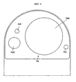
- Figure 4 shows a plan view of an embodiment of a coupling device half according to the invention.
- FIG. 1 generally designates an internal combustion engine which has six cylinders, and 2 designates the engine inlet manifold. Openings 2a which communicate with the respective cylinders of the engine 1 are shown with dashed contours.
- An element formed with flow ducts is generally designated 3 and is formed with two halves 4a, 5a of coupling devices 4, 5, which halves 4a, 5a communicate with the ducts, and the corresponding halves 4b, 5b of which coupling devices 4, 5 are disposed on the inlet manifold 2.
- the coupling device half 4b is thus mounted at one end of a duct 6 mounted on the inlet manifold 2.
- the coupling device half 4b is connected to the duct 6 and to an engine coolant discharge pipe 7, such that the connections do not communicate with one another but communicate with respective flow ducts of the element 3 via the coupling device half 4a.
- the coupling device half 5b is connected to the inlet manifold 2 and to a feed pipe 8 for coolant of the engine 1. Said connections do not communicate with one another but communicate with respective flow ducts of the element 3 via the coupling half 5a.
- Figure 1 which shows an engine fed by a turbo assembly 9, illustrates a flow path for air of combustion of the engine 1 from the turbo assembly 9 via the duct 6, the coupling device 4, the air duct of the element 3, the coupling device 5 and the inlet manifold 2 to the openings 2a.
- a flow path for coolant of the engine 1 Arranged in a corresponding manner is a flow path for coolant of the engine 1 from the feed pipe 8 with the coupling device 5, the coolant duct of the element 3, the coupling device 4 and the discharge pipe 7.
- the object of the turbo assembly 9 is to compress the air of combustion in order to provide a greater amount of air for the engine per cycle. During compression, the air of combustion is heated and, in order to utilize the advantage attained by compression, the air of combustion has to be cooled before it reaches the inlet manifold 2.
- the element 3 in this case serves as a charging air cooler and, according to the invention, is of the so-called integral type, i.e. it is of the type without a casing. With this construction there is practically no risk of the coolant passing into the air of combustion. It will be appreciated that, with the construction and installation of the charging air cooler in accordance with the invention, said cooler can easily be dimensioned to suit the particular requirements.
- FIG 2 in which, where appropriate, the same reference numerals are used as in Figure 1, shows, as mentioned, an embodiment of the invention used in the case of a normally aspirated engine.
- 10 designates an air filter which is connected to the duct 6 in place of the turbo assembly 9.
- the element 3 according to the invention is a through-flow pipe 3' which allows the air of combustion of the engine 1 to flow from the air filter 10 to the inlet manifold 2 but is arranged so as to block the flow of coolant between the feed and discharge pipes 8 and 7, respectively.
- FIG 3 which shows a turbocharged engine
- the unit according to the invention is a through-flow pipe 3' as in Figure 2, but a turbo assembly 9 is connected to the duct 5, as in Figure 1.
- the coupling device half shown in plan view in Figure 4 is, for example, the part designated 4a in Figure 1.
- the coupling device half 4a has, on the one hand, two continuous bolt holes 4a1 for mounting the element 3 with the duct 6 via its coupling device half 4b and, on the other hand, two continuous openings 4a2, 4a3.
- the opening 4a2 communicates with the discharge pipe 7 whilst the opening 4a3 communicates with the duct 6.
- sealing elements such as O-rings have been omitted.
- the arrangement according to the invention enables the same basic engine to be used for a plurality of different engine designs having performance levels adapted to particular requirements.
Landscapes
- Engineering & Computer Science (AREA)
- Physics & Mathematics (AREA)
- Thermal Sciences (AREA)
- Chemical & Material Sciences (AREA)
- Combustion & Propulsion (AREA)
- Mechanical Engineering (AREA)
- General Engineering & Computer Science (AREA)
- Supercharger (AREA)
- Quick-Acting Or Multi-Walled Pipe Joints (AREA)
Description
Claims (3)
- An inlet manifold (2) apparatus for an internal combustion engine (1), comprising an element (3; 3') which is formed with flow ducts and which is formed with two coupling device halves (4a, 5a) which communicate with the ducts and which is connected to two corresponding coupling device halves (4b, 5b) which are disposed on the inlet manifold (2) and of which one (4b) of said coupling device halves communicates with a member (9; 10) for feeding air of combustion for the engine and with a discharge pipe (7) for coolant and of which the other (5b) of said coupling device halves communicates with the inlet manifold (2) and with a feed pipe (8) for said coolant.
- An inlet manifold apparatus according to Claim 1, wherein said member for feeding air of combustion for the engine (1) comprises a turbocharger (9), and wherein the element (3) formed with flow ducts is an integral-type charging air cooler, i.e. of the type without a casing, arranged so that the temperature of the air of combustion is adapted to the operating requirements of the engine (1) by means of said coolant.
- An inlet manifold apparatus according to Claim 1, wherein the engine is of the normally aspirated type, and wherein the element (3; 3') formed with flow ducts has a through-flow pipe (3') for supplying air of combustion for the engine to the inlet manifold (2) and is arranged such that it blocks the flow of coolant between the feed and discharge pipes (8 and 7, respectively).
Applications Claiming Priority (3)
| Application Number | Priority Date | Filing Date | Title |
|---|---|---|---|
| SE9404077 | 1994-11-24 | ||
| SE9404077A SE502710C2 (en) | 1994-11-24 | 1994-11-24 | Device at an internal combustion engine suction pipe |
| PCT/SE1995/001270 WO1996016260A1 (en) | 1994-11-24 | 1995-10-26 | Arrangement at the intake manifold of an internal combustion engine |
Publications (2)
| Publication Number | Publication Date |
|---|---|
| EP0789808A1 EP0789808A1 (en) | 1997-08-20 |
| EP0789808B1 true EP0789808B1 (en) | 2001-01-03 |
Family
ID=20396103
Family Applications (1)
| Application Number | Title | Priority Date | Filing Date |
|---|---|---|---|
| EP95938676A Expired - Lifetime EP0789808B1 (en) | 1994-11-24 | 1995-10-26 | Arrangement at the intake manifold of an internal combustion engine |
Country Status (7)
| Country | Link |
|---|---|
| US (1) | US6073616A (en) |
| EP (1) | EP0789808B1 (en) |
| JP (1) | JPH10509225A (en) |
| BR (1) | BR9509914A (en) |
| DE (1) | DE69519806T2 (en) |
| SE (1) | SE502710C2 (en) |
| WO (1) | WO1996016260A1 (en) |
Families Citing this family (9)
| Publication number | Priority date | Publication date | Assignee | Title |
|---|---|---|---|---|
| US6805108B2 (en) | 2002-12-20 | 2004-10-19 | Caterpillar Inc | Heat exchanger for a supercharger |
| US6976479B1 (en) * | 2004-08-10 | 2005-12-20 | Electro-Motive Diesel, Inc. | Engine with optimized engine charge air-cooling system |
| DE102005044291A1 (en) * | 2005-09-16 | 2007-03-29 | Behr Industry Gmbh & Co. Kg | Stacking plate heat exchanger, in particular intercooler |
| DE102007024631A1 (en) * | 2007-05-24 | 2008-11-27 | Behr Gmbh & Co. Kg | Integrated charging module |
| US9303552B2 (en) * | 2012-12-31 | 2016-04-05 | General Electric Company | Diesel engine and transverse turbocharger |
| CZ2013278A3 (en) * | 2013-04-11 | 2014-10-22 | Halla Visteon Climate Control Corporation | Heat-exchange apparatus |
| KR101534726B1 (en) * | 2013-12-06 | 2015-07-07 | 현대자동차 주식회사 | Engine system having turbo charger |
| KR101534733B1 (en) * | 2013-12-16 | 2015-07-07 | 현대자동차 주식회사 | Engine system having turbo charger |
| JP6462351B2 (en) * | 2014-12-19 | 2019-01-30 | 三菱重工業株式会社 | Internal combustion engine |
Family Cites Families (7)
| Publication number | Priority date | Publication date | Assignee | Title |
|---|---|---|---|---|
| US2622571A (en) * | 1950-02-02 | 1952-12-23 | Fehling Hans Reinhard | Internal-combustion engine and the operation thereof |
| US3091228A (en) * | 1961-04-17 | 1963-05-28 | Caterpillar Tractor Co | Engine with turbocharger and aftercooling |
| US4191148A (en) * | 1977-06-30 | 1980-03-04 | Cummins Engine Company, Inc. | Aftercooler assembly for internal combustion engine |
| US4269158A (en) * | 1978-07-06 | 1981-05-26 | Allis-Chalmers Corporation | Intercooler for internal combustion engine |
| WO1983002481A1 (en) * | 1982-01-13 | 1983-07-21 | Tholen, Paul | Internal combustion supercharged motor with heat exchanger of the combustion air |
| US4476842A (en) * | 1982-09-20 | 1984-10-16 | Allis-Chalmers Corporation | Intercooler damper support |
| US4452216A (en) * | 1982-09-27 | 1984-06-05 | Allis-Chalmers Corporation | Even temperature intercooler |
-
1994
- 1994-11-24 SE SE9404077A patent/SE502710C2/en unknown
-
1995
- 1995-10-26 JP JP8516762A patent/JPH10509225A/en not_active Ceased
- 1995-10-26 EP EP95938676A patent/EP0789808B1/en not_active Expired - Lifetime
- 1995-10-26 DE DE69519806T patent/DE69519806T2/en not_active Expired - Fee Related
- 1995-10-26 US US08/836,944 patent/US6073616A/en not_active Expired - Lifetime
- 1995-10-26 WO PCT/SE1995/001270 patent/WO1996016260A1/en not_active Ceased
- 1995-10-26 BR BR9509914A patent/BR9509914A/en not_active IP Right Cessation
Also Published As
| Publication number | Publication date |
|---|---|
| EP0789808A1 (en) | 1997-08-20 |
| JPH10509225A (en) | 1998-09-08 |
| WO1996016260A1 (en) | 1996-05-30 |
| DE69519806D1 (en) | 2001-02-08 |
| SE9404077L (en) | 1995-12-11 |
| BR9509914A (en) | 1997-09-30 |
| DE69519806T2 (en) | 2001-08-09 |
| SE502710C2 (en) | 1995-12-11 |
| US6073616A (en) | 2000-06-13 |
| SE9404077D0 (en) | 1994-11-24 |
Similar Documents
| Publication | Publication Date | Title |
|---|---|---|
| US6116026A (en) | Engine air intake manifold having built-in intercooler | |
| US4269158A (en) | Intercooler for internal combustion engine | |
| US6293264B1 (en) | Supercharger aftercooler for internal combustion engines | |
| US6457442B1 (en) | Liquid-cooled internal combustion engine | |
| GB1560769A (en) | Low-compression piston internalcombustion engine with turbosupercharging and control of the intake air temperature | |
| US20040050374A1 (en) | Exhaust-gas recirculation system of an internal combustion engine | |
| US20020189255A1 (en) | Combined remote first intake air aftercooler and a second fluid from an engine cooler for an engine | |
| US6073616A (en) | Arrangement at the intake manifold of an internal combustion engine | |
| EP0167807B1 (en) | A supercharger system for use with heat engines | |
| WO2001044739A3 (en) | Switched heat exchanger | |
| US4708120A (en) | Apparatus and method for treating air from a turbocharger | |
| WO2001069064B1 (en) | Cast heat exchanger system | |
| JP2882438B2 (en) | Intake manifold for internal combustion engine | |
| US20050126168A1 (en) | Internal combustion engine | |
| WO1988006679A1 (en) | Apparatus and method for treating air from a turbocharger | |
| CN1226532C (en) | Intake manifolds for small internal combustion engines | |
| JP5423169B2 (en) | Internal combustion engine | |
| JPS5820924A (en) | Intake device for engine with supercharger | |
| CA2217770A1 (en) | System for controlling the temperature of a temperature control fluid in an internal combustion engine | |
| JPH09242549A (en) | Inter cooler | |
| JPS5930168Y2 (en) | Air heater device for supercharged engine with intercooler | |
| JPH01117916A (en) | Cooler of water cooling type engine | |
| JPS5813075Y2 (en) | Charge air heating device for internal combustion engine with supercharger | |
| CN109519267B (en) | Cooling system comprising air inlet and exhaust pipeline | |
| JPS60224939A (en) | Engine with turbosupercharger |
Legal Events
| Date | Code | Title | Description |
|---|---|---|---|
| PUAI | Public reference made under article 153(3) epc to a published international application that has entered the european phase |
Free format text: ORIGINAL CODE: 0009012 |
|
| 17P | Request for examination filed |
Effective date: 19970516 |
|
| AK | Designated contracting states |
Kind code of ref document: A1 Designated state(s): DE ES FR GB IT SE |
|
| 17Q | First examination report despatched |
Effective date: 19990826 |
|
| GRAG | Despatch of communication of intention to grant |
Free format text: ORIGINAL CODE: EPIDOS AGRA |
|
| 17Q | First examination report despatched |
Effective date: 19990826 |
|
| GRAG | Despatch of communication of intention to grant |
Free format text: ORIGINAL CODE: EPIDOS AGRA |
|
| GRAH | Despatch of communication of intention to grant a patent |
Free format text: ORIGINAL CODE: EPIDOS IGRA |
|
| GRAH | Despatch of communication of intention to grant a patent |
Free format text: ORIGINAL CODE: EPIDOS IGRA |
|
| GRAA | (expected) grant |
Free format text: ORIGINAL CODE: 0009210 |
|
| AK | Designated contracting states |
Kind code of ref document: B1 Designated state(s): DE ES FR GB IT SE |
|
| PG25 | Lapsed in a contracting state [announced via postgrant information from national office to epo] |
Ref country code: SE Free format text: LAPSE BECAUSE OF FAILURE TO SUBMIT A TRANSLATION OF THE DESCRIPTION OR TO PAY THE FEE WITHIN THE PRESCRIBED TIME-LIMIT Effective date: 20010103 Ref country code: FR Free format text: LAPSE BECAUSE OF FAILURE TO SUBMIT A TRANSLATION OF THE DESCRIPTION OR TO PAY THE FEE WITHIN THE PRESCRIBED TIME-LIMIT Effective date: 20010103 Ref country code: ES Free format text: THE PATENT HAS BEEN ANNULLED BY A DECISION OF A NATIONAL AUTHORITY Effective date: 20010103 |
|
| REF | Corresponds to: |
Ref document number: 69519806 Country of ref document: DE Date of ref document: 20010208 |
|
| ITF | It: translation for a ep patent filed | ||
| EN | Fr: translation not filed | ||
| PG25 | Lapsed in a contracting state [announced via postgrant information from national office to epo] |
Ref country code: GB Free format text: LAPSE BECAUSE OF NON-PAYMENT OF DUE FEES Effective date: 20011026 |
|
| PLBE | No opposition filed within time limit |
Free format text: ORIGINAL CODE: 0009261 |
|
| STAA | Information on the status of an ep patent application or granted ep patent |
Free format text: STATUS: NO OPPOSITION FILED WITHIN TIME LIMIT |
|
| REG | Reference to a national code |
Ref country code: GB Ref legal event code: IF02 |
|
| 26N | No opposition filed | ||
| GBPC | Gb: european patent ceased through non-payment of renewal fee |
Effective date: 20011026 |
|
| PGFP | Annual fee paid to national office [announced via postgrant information from national office to epo] |
Ref country code: DE Payment date: 20061009 Year of fee payment: 12 |
|
| PGFP | Annual fee paid to national office [announced via postgrant information from national office to epo] |
Ref country code: IT Payment date: 20061031 Year of fee payment: 12 |
|
| PG25 | Lapsed in a contracting state [announced via postgrant information from national office to epo] |
Ref country code: DE Free format text: LAPSE BECAUSE OF NON-PAYMENT OF DUE FEES Effective date: 20080501 |
|
| PG25 | Lapsed in a contracting state [announced via postgrant information from national office to epo] |
Ref country code: IT Free format text: LAPSE BECAUSE OF NON-PAYMENT OF DUE FEES Effective date: 20071026 |