EP0789640B1 - Steuerung von schweissbandnaehten mittels videokamera und fuzzy-logik - Google Patents
Steuerung von schweissbandnaehten mittels videokamera und fuzzy-logik Download PDFInfo
- Publication number
- EP0789640B1 EP0789640B1 EP95938779A EP95938779A EP0789640B1 EP 0789640 B1 EP0789640 B1 EP 0789640B1 EP 95938779 A EP95938779 A EP 95938779A EP 95938779 A EP95938779 A EP 95938779A EP 0789640 B1 EP0789640 B1 EP 0789640B1
- Authority
- EP
- European Patent Office
- Prior art keywords
- current
- puddle
- weld
- rule
- membership
- Prior art date
- Legal status (The legal status is an assumption and is not a legal conclusion. Google has not performed a legal analysis and makes no representation as to the accuracy of the status listed.)
- Expired - Lifetime
Links
- 238000003466 welding Methods 0.000 title claims description 23
- 238000004458 analytical method Methods 0.000 title description 2
- 230000006870 function Effects 0.000 claims description 50
- 238000000034 method Methods 0.000 claims description 18
- 230000008859 change Effects 0.000 claims description 16
- 230000007423 decrease Effects 0.000 claims description 8
- RTAQQCXQSZGOHL-UHFFFAOYSA-N Titanium Chemical compound [Ti] RTAQQCXQSZGOHL-UHFFFAOYSA-N 0.000 claims description 7
- 238000012545 processing Methods 0.000 claims description 6
- 229910001220 stainless steel Inorganic materials 0.000 claims description 5
- 238000003384 imaging method Methods 0.000 claims description 4
- 230000005540 biological transmission Effects 0.000 claims description 2
- 230000008878 coupling Effects 0.000 claims 1
- 238000010168 coupling process Methods 0.000 claims 1
- 238000005859 coupling reaction Methods 0.000 claims 1
- 239000000463 material Substances 0.000 description 12
- 230000008569 process Effects 0.000 description 10
- 239000010936 titanium Substances 0.000 description 6
- 229910052719 titanium Inorganic materials 0.000 description 6
- 230000003287 optical effect Effects 0.000 description 5
- 238000013459 approach Methods 0.000 description 4
- 239000010935 stainless steel Substances 0.000 description 4
- 239000011324 bead Substances 0.000 description 3
- 239000000945 filler Substances 0.000 description 3
- 239000011261 inert gas Substances 0.000 description 3
- XKRFYHLGVUSROY-UHFFFAOYSA-N Argon Chemical compound [Ar] XKRFYHLGVUSROY-UHFFFAOYSA-N 0.000 description 2
- 230000008901 benefit Effects 0.000 description 2
- 238000004364 calculation method Methods 0.000 description 2
- 230000001419 dependent effect Effects 0.000 description 2
- 238000010586 diagram Methods 0.000 description 2
- 230000014509 gene expression Effects 0.000 description 2
- 230000005484 gravity Effects 0.000 description 2
- 229910052751 metal Inorganic materials 0.000 description 2
- 239000002184 metal Substances 0.000 description 2
- 238000004886 process control Methods 0.000 description 2
- 241000435809 Sarea Species 0.000 description 1
- 229910052786 argon Inorganic materials 0.000 description 1
- 238000013473 artificial intelligence Methods 0.000 description 1
- 238000013528 artificial neural network Methods 0.000 description 1
- 238000011217 control strategy Methods 0.000 description 1
- 238000013461 design Methods 0.000 description 1
- 238000010891 electric arc Methods 0.000 description 1
- 238000005516 engineering process Methods 0.000 description 1
- 239000007789 gas Substances 0.000 description 1
- 238000010438 heat treatment Methods 0.000 description 1
- 238000013507 mapping Methods 0.000 description 1
- 230000007246 mechanism Effects 0.000 description 1
- 238000002844 melting Methods 0.000 description 1
- 230000008018 melting Effects 0.000 description 1
- 150000002739 metals Chemical class 0.000 description 1
- 238000012360 testing method Methods 0.000 description 1
- WFKWXMTUELFFGS-UHFFFAOYSA-N tungsten Chemical compound [W] WFKWXMTUELFFGS-UHFFFAOYSA-N 0.000 description 1
- 229910052721 tungsten Inorganic materials 0.000 description 1
- 239000010937 tungsten Substances 0.000 description 1
Images




Classifications
-
- B—PERFORMING OPERATIONS; TRANSPORTING
- B23—MACHINE TOOLS; METAL-WORKING NOT OTHERWISE PROVIDED FOR
- B23K—SOLDERING OR UNSOLDERING; WELDING; CLADDING OR PLATING BY SOLDERING OR WELDING; CUTTING BY APPLYING HEAT LOCALLY, e.g. FLAME CUTTING; WORKING BY LASER BEAM
- B23K9/00—Arc welding or cutting
- B23K9/10—Other electric circuits therefor; Protective circuits; Remote controls
- B23K9/1006—Power supply
- B23K9/1043—Power supply characterised by the electric circuit
- B23K9/1056—Power supply characterised by the electric circuit by using digital means
- B23K9/1062—Power supply characterised by the electric circuit by using digital means with computing means
-
- B—PERFORMING OPERATIONS; TRANSPORTING
- B23—MACHINE TOOLS; METAL-WORKING NOT OTHERWISE PROVIDED FOR
- B23K—SOLDERING OR UNSOLDERING; WELDING; CLADDING OR PLATING BY SOLDERING OR WELDING; CUTTING BY APPLYING HEAT LOCALLY, e.g. FLAME CUTTING; WORKING BY LASER BEAM
- B23K9/00—Arc welding or cutting
- B23K9/12—Automatic feeding or moving of electrodes or work for spot or seam welding or cutting
- B23K9/127—Means for tracking lines during arc welding or cutting
- B23K9/1272—Geometry oriented, e.g. beam optical trading
- B23K9/1274—Using non-contact, optical means, e.g. laser means
Definitions
- This invention relates to automated GTAW (gas tungsten arc welding) using computer based signal processing and programmed logic to control welding functions, in particular, welding control using fuzzy logic analysis of video imaged puddle dimensions.
- GTAW gas tungsten arc welding
- GTAW is a widely used welding process, illustrated in the closest prior art documents U.S. patent 5,275,327 and the article "Sensing of the Weld Pool Depth With Neural Network and Fuzzy Control" by Yasuyoshi Kaneko et al, in PROCEEDINGS OF The IECON, 1993, vol. 1 dated 15 November 1993, by which an electric arc is formed by a welding torch, a shroud of inert gas, such as argon, is applied from the torch to the weld area and a weld and filler material, such as titanium or 17-4PH stainless steel, is supplied as a relatively thin wire.
- inert gas such as argon
- the weld material forms a so-called "puddle" in the weld area, e.g., the space or joint between two pieces.
- the characteristics of the puddle are dependent on the type of wire, weld material, thickness and heat sink properties.
- Stainless steel is known to produce a weld bead that has waves or ripples to the eye. Titanium flows more easily, producing a generally smooth weld bead.
- the characteristics of the puddle indicate the integrity of the weld in the sense that if the arc is too hot, the puddle will be larger.
- the temperature of the arc is determined by the arc current. The current heats the work-piece and the size of the puddle is a function of the temperature in the weld area. More current is needed to maintain the work-piece weld area at a given temperature as the work-piece gets thicker, and conversely, if the material thickness decreases, the weld area will get hotter. This can lead to changes in puddle width, indicating the change in the materials thickness. Thus, the weld characteristics will change as the work-piece's thickness changes.
- Automated GTAW attempts to provide more uniform welds by controlling temperature, motion of the head and wire feed rates.
- U.S. patent 4,724,302 describes an automated welding process that maintains certain bead dimensions within specified ranges to achieve proper weld strength.
- the system employs a method of automatically controlling a weld head (puddle) based on the characteristics of the head height and width using interpolated values of head height and width.
- this approach typifies those that employ Boolean logic, one in which a particular object, for example a variable, is or is not a member of a given set of parameters.
- Traditional systems in other words, have used rigid "set theory" using crisp values.
- Welding is an area of technology that is particularly suited to approaches that do not use rigid Boolean set theory, but instead uses set theory in which a particular parameter has a degree of membership in one or more groups. This approach imitates human thinking and is called "fuzzy logic", in contrast with rigid Boolean logic that is the foundation of tradition computational control systems.
- Fuzzy logic was introduced by Zadeh in 1965, and, generally speaking, deals with such inherently fuzzy human concepts as " very, most, few” but as applied in a rigid mathematical framework. This may be called “fuzzy subset theory”.
- fuzzy logic The application of fuzzy logic to systems that have used Boolean set theory in the past, has produced the fast growing field of so-called “artificial intelligence”.
- artificial intelligence The objective of these systems is to capture the knowledge of the human expert in a particular problem area, representing it in a modular, expandable structure and transferring it to others.
- the process involves considering the questions of process physics, knowledge acquisition, knowledge representation, inference mechanism, control strategies, user interfaces and uncertainty.
- the objects of the present invention include providing an improved GTAW welding system using fuzzy logic control with a reliable way to measure the puddle and a flexible way to apply the weld wire into the puddle.
- each membership function is defined by a range for a puddle dimension.
- each membership function is defined by an x value that defines a dimension (width or length) calling for a big decrease in current and a degree of membership or fit in the function for that dimension as an associated y coordinate.
- the "degree of fit" is the alpha ( ⁇ ) value
- Total current is then compared to the actual current to produce an error that is used to modify the actual current to achieve the total current.
- Total Current current moment current area
- additional fuzzy logic subsets are used for puddle length and the current area and current moment are computed from each of those sets in which the measured dimensions fall.
- the puddle width may be BN (very narrow, calling for a big increase in current) but the length may be BP (very wide, calling for a big decrease in the current).
- the weld torch contains a wire feed that may be remotely moved around the weld puddle during the weld process to adjust the wire feed position relative to the weld direction.
- the head contains a gear system coupled to a servo motor.
- a plurality of puddle values for length and width are obtained from the optical view of the puddle. Some of these values are discarded in a computational process that determines the centerline of the puddle based upon the distribution of the puddle widths over several successive scans.
- the present invention provides an extremely precise and repeatable weld and minimizes excessive weld input temperatures. Another feature is that the invention provides a versatile wire feed arrangement for robotic GTAW welders.
- Membership functions and rules provide the ability to handle complex relationships easily, which is an important benefit of fuzzy logic.
- An application's rules and membership functions also contain the expert's knowledge about a system.
- the adjectives used to formulate rules are more rigorously defined in the application's membership functions.
- the shapes of the membership functions are generally triangular and trapezoidal.
- the control system's logic may be fuzzy, but measured inputs from a physical system, and the outputs required to control it will be precise. Precise values in fuzzy logic systems are termed "crisp".
- Fuzzy logic is an extension of traditional Boolean logic, while Boolean logic requires a statement or condition to be either completely TRUE or completely FALSE. Fuzzy logic allows partial truth and potential falseness.
- Fuzzy logic is derived from the more general theory of fuzzy sets. Functions in a welding system are created relating "measured weld puddle widths" to "acceptable weld puddle widths". Thus, it can be calculated that the measured weld puddle width is 60% TRUE and 40% FALSE, for example.
- this measured puddle width value maps to two membership functions: P(positive) and BP(big positive).
- P .320 to .360
- BP .340 to 1.00
- Two membership functions are operated on in this example: the 0.355 measured puddle width maps to the degree of membership of .4 for P and 0.6 for BP.
- the 0.4 and 0.6 indicates the degree of membership for each fuzzy logic membership function that the 0.355 maps into. Therefore, the actual measured width belongs to two membership functions or membership sets.
- the membership function uses an average, weighted by the respective degree of membership values to calculate the crisp or defuzzified output.
- the area and the moment definition are application specific and are dependent on the process physics, materials, and the welded process control equipment.
- the moments and area are defined as follows: Membership Function Moment Area BN -2.0 2.0 N -1.0 2.0 Z 0 2.0 P 1.0 2.0 BP 2.0 2.0
- the new current value is used to adjust the systems current output using feedback control, as described below.
- the 17-4PH rule sets are as follows, as defined from Figs 2 and 3
- measured weld puddle width is BN and measured weld puddle length is BP, THEN current is P.
- measured weld puddle width is N and measured weld puddle length is BN THEN current is P.
- measured weld puddle width is N and measured weld puddle length is BP, THEN current is Z.
- measured weld puddle width is Z and measured weld puddle length is BN, THEN current is Z.
- measured weld puddle width is Z and measured weld puddle length is Z
- THEN current is Z.
- measured weld puddle width is P and measured weld puddle length is BN, THEN current is Z.
- measured weld puddle width is P and measured weld puddle length is Z
- THEN current is Z.
- measured weld puddle width is BP and measured weld puddle length is BN, THEN current is BN.
- measured weld puddle width is BP and measured weld puddle length is N
- THEN current is N.
- measured weld puddle width is BP and measured weld puddle length is Z, THEN current is N.
- measured weld puddle width is BP and measured weld puddle length is P, THEN current is BN.
- measured weld puddle width is BP and measured weld puddle length is BP, THEN current is BN.
- the 0.310 weld puddle length maps as follows: It has two fuzzy logic membership functions. Rule 1) the weld puddle length is in P with a membership of 0.6 and Rule 2) the weld puddle length is also in Z with a membership there of 0.5. For the weld puddle width of 0.225, the width maps to two fuzzy logic membership functions as well: Rule 3) in the function for Z, with a degree of membership there of 0.3 and Rule 4) in the function N, with a degree of membership of 0.8. In this case these four (4) out of the above twenty five (25) rules will fire: Rule 8, 9,13, and 14. The computation for current assumes these notations:
- New current actual measured current + I
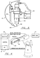
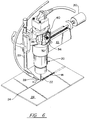
- Fig. 4 shows a robotic welding arm 10 on a base and a controller 14 that includes a monitor 16 for providing real-time graphic information of weld operation, such as the view of the weld puddle shown in Fig.8.
- a weld (e.g., GTAW) torch 20 (see also Fig 6) is located at the end of the arm 10, and includes an electrode 22 for providing the arc current that heats a joint 24 on a work-piece 26.
- Inert gas is supplied around the electrode 22 from a supply 13.
- the current is provided from a power supply (PS) 15, which is controlled by the controller to produce the required current according to the fuzzification and defuzzification process explained previously and the basic program steps described below.
- PS power supply
- Weld wire 28 is fed from a line feed motor 31 through a rotatable wire feed arm 29, melting to form the puddle, which has a rippled or wavy pattern as shown, the characteristic of 17-4PH weld material. (When Titanium is used the puddle is generally smooth.)
- Optical filters 40 lie in the path between the camera and the work-piece, as illustrated in Fig. 7
- a second motor 30 rotates and, through the gears 32 and 34, rotates wire guide arm 29, whose position is sensed by a position sensor 33 coupled to the arm (e.g. circular gear rack and pinion, as shown, or a timing belt) around a torch optics section 36, which contains, as shown in Fig.
- a strobe 38 narrows the bandwidth of the optical and infra red energy that reaches the camera, mainly limiting the energy to light in the wavelength range of the strobe 38.
- Strobe light is pulsed at a frequency determined by a strobe signal 55 from a signal processor (not shown in Fig. 4, but 50 in Fig. 10) on the line 44a.
- the result is the snapshot of the weld puddle as shown in Fig. 8, which may have any of the characteristics, over several snapshots, of length and width shown in the fuzzy logic rules shown in Fig 9.
- the overall system includes a microcontroller/signal processor 50 with a memory (MEM) 52 to store retrievable values corresponding to 1) the membership function shown in the fuzzy logic table (Figs 1, 2 and 3); and 2) the area and moment of each set BN, N, Z, P and BP (Fig. 11).
- the signal processor 50 also includes an input/output section or interface for signal transceiving.
- the microcontroller receives from the current control 54 a signal, Current Out, indicating the weld current L and provides a signal, Calculated Current, which is generated using the fuzzification and defuzzification signal processing described above based on' the strobed image produced from an optics section 56.
- the current is provided from a power supply 58.
- a signal, Wire Feed Velocity, is provided from a wire feed velocity sensor 60.
- the motor 30 receives a signal, Commanded Arm Position, to place the wire feed arm in a desired location at which the difference between the arm location signal and the commanded arm location is zero.
- the flow-chart shown in Fig. 12 illustrates the steps employed by the system controller, through the signal processor 50, using the previously described fuzzification and defuzzification relationships when welding the seam 18 in Fig. 6.
- a number of frames of the puddle are obtained through successive strobing, providing puddle dimension data in step S2, for instance the length and width described in above example 2.
- the puddle width data is processed to yield the puddle centerline based upon the range of puddle width.
- the membership tables, e.g., Figs 1, 2 and 3 are addressed by mapping the length and width to the membership functions, producing the degree of membership or alpha values.
- step S5 the area and moment for each function with an alpha greater than zero is recalled.
- step S7 the current area and moment for each function with an alpha greater than zero is computed using equations 2 and 3 and the steps described, in either example 1 or 2 above.
- the values for I are summed in step S8 and the sum or total is compared with the actual current (current out in Fig. 10) in step S9, producing an error signal, which the signal processor 50 uses in step S10 to compute the required change in current to bring the error to zero in step S9.
Landscapes
- Engineering & Computer Science (AREA)
- Physics & Mathematics (AREA)
- Plasma & Fusion (AREA)
- Mechanical Engineering (AREA)
- Theoretical Computer Science (AREA)
- Optics & Photonics (AREA)
- Geometry (AREA)
- Feedback Control In General (AREA)
- Arc Welding In General (AREA)
Claims (13)
- Schweißgerät mit einem Brenner (20), einer Abbildungseinrichtung (36) und einer Steuerung (14) zum Steuern des dem Brenner zufließenden Schweißstroms,
dadurch gekennzeichnet, daß die Steuerung eine Signalverarbeitungseinrichtung aufweist, dieSignale von der Abbildungseinrichtung (36) empfängt, um eine oder mehrere Abmessungen einer Schweißluppe zu ermitteln, die von dem Schweißgerät gebildet wird;die Zugehörigkeitsgrade der einen oder der mehreren Abmessungen in einer Mehrzahl benachbarter Fuzzylogikmengen bestimmt, welche mögliche Luppenabmessungen von einem Minimum zu einem Maximum hin abdecken;aus den Fuzzylogikmengen, für die die Zugehörigkeitsgrade von Null verschieden sind, eine Mehrzahl möglicher Stromänderungswette ermittelt, indem eine Mehrzahl von Fuzzyregeln verwendet wird; undaus den möglichen Stromänderungswerten dadurch ein Stromänderungssignal ermittelt, daß Stromwerte der Regeln summiert werden, wobei die Stromwerte als Proportionalfunktion der ermittelten Zugehörigkeitsgrade bestimmt werden. - Schweißgerät nach Anspruch 1, bei dem eine Breitenabmessung der Schweißluppe ermittelt wird.
- Schweißgerät nach Anspruch 1, bei dem sowohl eine Breitenabmessung als auch eine Längenabmessung der Schweißluppe ermittelt wird, wobei die Zugehörigkeitsgrade für die Breitenabmessung in einer Mehrzahl von Breiten-Fuzzylogikmengen ermittelt wird, und die Zugehörigkeitsgrade für die Längenabmessung in einer Mehrzahl von Längen-Fuzzylogikmengen bestimmt werden.
- Schweißgerät nach Anspruch 2, mit einem Drahtzuführer, der Titandraht zuführt, wobei es fünf Fuzzylogikregeln entsprechend fünf Luppenbreiten-Fuzzymengen gibt und fünf mögliche Stromänderungswerte für eine starke Stromzunahme, für eine Stromzunahme, für keine Stromänderung, für eine Stromabnahme und für eine starke Stromabnahme bereitgestellt werden.
- Schweißgerät nach Anspruch 3, mit einem Drahtzuführer, der Draht aus rostfreiem Stahl zuführt, wobei es fünfundzwanzig Fuzzylogikregeln entsprechend fünf Luppenlängen-Fuzzymengen und fünf Luppenbreiten-Fuzzymengen gibt, wobei fünf mögliche Stromänderungswerte für eine starke Stromzunahme, für eine Stromzunahme, für keine Stromänderung, für eine Stromabnahme und für eine starke Stromabnahme bereitgestellt werden.
- Schweißgerät nach einem vorhergehenden Anspruch, bei dem die Stromwerte der Regeln Strommomentenwerte und Stromflächenwerte enthalten, von denen die Strommomentenwerte und die Stromflächenwerte bestimmt werden aus einer Multiplikation von mindestens einem der Zugehörigkeitsgrade der einen oder mehreren Luppenabmessungen und einem Momentenwert bzw. einem Flächenwert in Verbindung mit den möglichen Stromänderungswerten, und wobei die Strommomentenwerte aufsummiert werden, die Stromflächenwette aufsummiert werden, und die aufsummierten Strommomentenwerte durch die aufsummierten Stromflächenwerte dividiert werden, um das Stromänderungssignal zu erhalten.
- Schweißgerät nach den Ansprüchen 3 und 6, bei dem der Strommomentenwert und der Stromflächenwert einer Regel bestimmt werden, indem das Minimum des Zugehörigkeitsgrads der Breitenabmessung in der zu der Regel gehörigen Breiten-Fuzzymenge und des Zugehörigkeitsgrads der Längenabmessung innerhalb der zu der Regel gehörigen Längen-Fuzzymenge genommen wird und dieses Minimum multipliziert wird mit dem Momentenwert bzw. dem Stromflächenwert, der zu dein Stromänderungswert der Regel gehört.
- Schweißgerät nach einem vorhergehenden Anspruch, umfassend einen an dein Brenner (20) angebrachten Drahtzuführer (29), der um die Achse des Brenners (20) senkrecht zu der Schweißluppe drehend bewegbar ist.
- Schweißgerät nach Anspruch 8, bei dem der Zuführer (29) über eine Übertragungskupplung (32, 34) mit einer Welle gekoppelt ist, und wobei der Zuführer (29) von einem die Welle drehenden Motor drehend angetrieben wird.
- Schweißgerät nach Anspruch 8 oder 9, umfassend einen Servoantrieb, der auf Signale von der Signalverarbeitungseinrichtung anspricht, um die Drahtzufuhr zu Stellen auf einander entgegengesetzten Seiten der Schweißluppe weiterzuschalten.
- Schweißgerät nach einem vorhergehenden Anspruch, bei dem die Abbildungseinrichtung (36) aufeinanderfolgende Video-Einzelbilder der Schweißluppe (18) liefert, und wobei die Signalverarbeitungseinrichtung eine Einrichtung aufweist, um die Mittellinie der Luppe (18) aus den Bildern zu ermitteln und ein erstes Zentrierungssignal zum Zentrieren des Brenners (20) über der Luppe (18) zu liefern.
- Schweißverfahren, umfassend folgende Schritte:Beleuchten einer Schweißluppe (18) mit stroboskopischem Licht während des Schweißens; undBereitstellen von Signalen, die kennzeichnend sind für eine oder mehrere Schweißluppenabmessungen, basierend auf individuellen Video-Einzelbildern der Schweißluppe, die aus dem stroboskopischen Licht in einer Videokamera innerhalb eines oberhalb der Luppe (18) befindlichen Schweißbrenners (20) erzeugt werden;
gekennzeichnet durch die Schritte:Speichern von N Zugehörigkeitsfunktionen, die jeweils einen Zugehörigkeitsgrad der einen oder mehreren Luppenabmessungen in einer Mehrzahl von Fuzzymengen angeben;In-Beziehung-Setzen der Fuzzymengen mit Schweißstromänderungswerten unter Verwendung von Fuzzyregeln und Abspeichern eines Momentenwerts und einer Fläche für jeden dieser Stromänderungswerte;Bereitstellen eines Alphasignals für jede Regel, die zündet, wobei das Alphasignal einer Regel den Zugehörigkeitsgrad der einen oder mehreren Abmessungen in den zu dieser Regel gehörigen Fuzzymengen angibt;Bereitstellen für jede Regel, für die ein Alphawert erzeugt wird, von Momenten- und Flächensignalen, die das Produkt des Alphawerts für die Regel mit dem Momentenwert bzw. dem Flächenwert des zu der Regel gehörigen Stromänderungswerts angeben; undÄndern des Schweißstroms als Funktion der Summe der Momentensignale, dividiert durch die Summe der Flächensignale. - Verfahren nach Anspruch 12, bei dem die Breiten- und Längenabmessungen der Luppe bestimmt werden, wobei das Alphasignal einer Regel der geringste der Zugehörigkeitsgrade der Breiten- und Längen-Luppenabmessungen in den zu der Regel gehörigen Breiten- und Längen-Fuzzymengen ist.
Applications Claiming Priority (3)
| Application Number | Priority Date | Filing Date | Title |
|---|---|---|---|
| US332633 | 1994-10-31 | ||
| US08/332,633 US5614116A (en) | 1994-10-31 | 1994-10-31 | Welding control using fuzzy logic analysis of video imaged puddle dimensions |
| PCT/US1995/013380 WO1996013354A1 (en) | 1994-10-31 | 1995-10-26 | Welding control using fuzzy logic analysis of video imaged puddle dimensions |
Publications (2)
| Publication Number | Publication Date |
|---|---|
| EP0789640A1 EP0789640A1 (de) | 1997-08-20 |
| EP0789640B1 true EP0789640B1 (de) | 1999-05-26 |
Family
ID=23299122
Family Applications (1)
| Application Number | Title | Priority Date | Filing Date |
|---|---|---|---|
| EP95938779A Expired - Lifetime EP0789640B1 (de) | 1994-10-31 | 1995-10-26 | Steuerung von schweissbandnaehten mittels videokamera und fuzzy-logik |
Country Status (5)
| Country | Link |
|---|---|
| US (2) | US5614116A (de) |
| EP (1) | EP0789640B1 (de) |
| JP (1) | JPH10507970A (de) |
| DE (1) | DE69509916T2 (de) |
| WO (1) | WO1996013354A1 (de) |
Families Citing this family (24)
| Publication number | Priority date | Publication date | Assignee | Title |
|---|---|---|---|---|
| JPH09141451A (ja) * | 1995-11-17 | 1997-06-03 | Miyachi Technos Corp | 抵抗溶接制御方法 |
| US6130407A (en) * | 1998-07-29 | 2000-10-10 | Tregaskiss, Ltd. | Arc welding torch |
| DE60035706T2 (de) | 1999-11-04 | 2008-04-30 | Aeromet Corp., Eden Prairie | Steuersystem zum deponieren von pulver in ein schmelzbad |
| JP4045713B2 (ja) * | 2000-01-31 | 2008-02-13 | 松下電器産業株式会社 | 自動機用溶接機 |
| PT1448334E (pt) * | 2001-11-15 | 2011-06-28 | Precitec Vision Gmbh & Co Kg | Processo e dispositivo para detetar a qualidade de uma costura de soldadura durante a soldadura de peças de trabalho |
| FR2836621B1 (fr) * | 2002-02-28 | 2004-04-16 | Snecma Services | Instrument de projection thermique |
| FR2836618B1 (fr) * | 2002-02-28 | 2004-04-16 | Snecma Services | Instrument de projection thermique |
| FR2836619B1 (fr) * | 2002-02-28 | 2004-04-16 | Snecma Services | Instrument de projection thermique |
| WO2003095135A1 (fr) * | 2002-05-13 | 2003-11-20 | Honda Giken Kogyo Kabushiki Kaisha | Equipement et procede de soudage tig |
| US7154064B2 (en) * | 2003-12-08 | 2006-12-26 | General Motors Corporation | Method of improving weld quality |
| US9937577B2 (en) | 2006-12-20 | 2018-04-10 | Lincoln Global, Inc. | System for a welding sequencer |
| US11072034B2 (en) | 2006-12-20 | 2021-07-27 | Lincoln Global, Inc. | System and method of exporting or using welding sequencer data for external systems |
| US10994358B2 (en) | 2006-12-20 | 2021-05-04 | Lincoln Global, Inc. | System and method for creating or modifying a welding sequence based on non-real world weld data |
| US10994357B2 (en) | 2006-12-20 | 2021-05-04 | Lincoln Global, Inc. | System and method for creating or modifying a welding sequence |
| US9104195B2 (en) | 2006-12-20 | 2015-08-11 | Lincoln Global, Inc. | Welding job sequencer |
| DE202008003757U1 (de) | 2008-03-18 | 2009-08-13 | Kuka Systems Gmbh | Drehanschlusskupplung |
| WO2009015850A2 (de) | 2007-08-02 | 2009-02-05 | Kuka Systems Gmbh | Drehanschlusskupplung |
| US8927901B2 (en) * | 2008-03-17 | 2015-01-06 | Alcoa Inc. | Buried-arc welding of metal work pieces with through-the-arc seam tracking |
| US8354608B2 (en) * | 2009-05-14 | 2013-01-15 | B6 Sigma, Inc. | Methods for control of a fusion welding process by maintaining a controlled weld pool volume |
| AT508696B1 (de) | 2009-09-11 | 2015-06-15 | Fronius Int Gmbh | Überwachungsmodul zur überwachung eines prozesses mit einem lichtbogen |
| AT511177B1 (de) | 2011-03-10 | 2015-12-15 | Fronius Int Gmbh | Verfahren und vorrichtung zur überwachung eines lichtbogenprozesses |
| CN107662056A (zh) * | 2016-07-28 | 2018-02-06 | 中国科学院沈阳自动化研究所 | 一种焊接送丝引导头 |
| CN117283090B (zh) * | 2023-09-19 | 2026-04-10 | 南京师范大学 | 一种实时调控气孔缺陷的铝合金电弧增材制造系统及方法 |
| CN117548824B (zh) * | 2024-01-11 | 2024-04-02 | 武汉新耐视智能科技有限责任公司 | 一种光学精密测定机器人激光远程焊接方法 |
Family Cites Families (13)
| Publication number | Priority date | Publication date | Assignee | Title |
|---|---|---|---|---|
| DE246931C (de) * | ||||
| JPS5542185A (en) * | 1978-09-22 | 1980-03-25 | Kawasaki Heavy Ind Ltd | Detecting device for arc welding or the like |
| US4613743A (en) * | 1984-12-03 | 1986-09-23 | General Electric Company | Arc welding adaptive process control system |
| DD246931A1 (de) * | 1986-02-25 | 1987-06-24 | Zentralinstitut Schweiss | Verfahren zum automatischen duennblechschweissen mit hilfe des wig-schweissverfahrens |
| US4724302A (en) * | 1987-03-30 | 1988-02-09 | General Electric Company | Bead process control with profiler |
| JP2861285B2 (ja) * | 1990-06-14 | 1999-02-24 | 株式会社明電舎 | 電縫管の溶接入熱制御装置 |
| US5270516A (en) * | 1991-04-01 | 1993-12-14 | Matsushita Electric Industrial Co., Ltd. | Arc welding machine |
| JP2803386B2 (ja) * | 1991-04-16 | 1998-09-24 | 株式会社明電舎 | 電縫管溶接管理方法およびその装置 |
| JPH0542367A (ja) * | 1991-08-09 | 1993-02-23 | Sansha Electric Mfg Co Ltd | ガスシールドアーク溶接電源の出力制御方法 |
| JPH07105194B2 (ja) * | 1991-09-24 | 1995-11-13 | 岩崎電気株式会社 | ランプ用ガラス管封止工程のファジイ制御装置 |
| JPH0584572A (ja) * | 1991-09-27 | 1993-04-06 | Hitachi Seiko Ltd | 半自動アーク溶接機 |
| JPH05177353A (ja) * | 1991-12-27 | 1993-07-20 | Hitachi Zosen Corp | 自動溶接用アークセンサ |
| US5275327A (en) * | 1992-10-13 | 1994-01-04 | Eg&G Idaho, Inc. | Integrated optical sensor |
-
1994
- 1994-10-31 US US08/332,633 patent/US5614116A/en not_active Ceased
-
1995
- 1995-10-26 JP JP8514631A patent/JPH10507970A/ja active Pending
- 1995-10-26 DE DE69509916T patent/DE69509916T2/de not_active Expired - Fee Related
- 1995-10-26 EP EP95938779A patent/EP0789640B1/de not_active Expired - Lifetime
- 1995-10-26 WO PCT/US1995/013380 patent/WO1996013354A1/en not_active Ceased
-
1999
- 1999-03-25 US US09/276,219 patent/USRE36926E/en not_active Expired - Fee Related
Also Published As
| Publication number | Publication date |
|---|---|
| USRE36926E (en) | 2000-10-31 |
| DE69509916D1 (de) | 1999-07-01 |
| JPH10507970A (ja) | 1998-08-04 |
| US5614116A (en) | 1997-03-25 |
| EP0789640A1 (de) | 1997-08-20 |
| WO1996013354A1 (en) | 1996-05-09 |
| DE69509916T2 (de) | 1999-09-30 |
Similar Documents
| Publication | Publication Date | Title |
|---|---|---|
| USRE36926E (en) | Welding control using fuzzy logic analysis of video imaged puddle dimensions | |
| Cheng et al. | Real-time sensing of gas metal arc welding process–A literature review and analysis | |
| Rout et al. | Weld seam detection, finding, and setting of process parameters for varying weld gap by the utilization of laser and vision sensor in robotic arc welding | |
| Chen et al. | Intelligent methodology for sensing, modeling and control of pulsed GTAW: Part 1--Bead-on-plate welding | |
| Kovacevic et al. | Neurofuzzy model-based weld fusion state estimation | |
| Liu et al. | A tutorial on learning human welder's behavior: Sensing, modeling, and control | |
| CN111738369A (zh) | 基于熔池视觉特征的焊熔透状态及熔深实时预测方法 | |
| Chen et al. | Robotic welding systems with vision-sensing and self-learning neuron control of arc welding dynamic process | |
| EP0520893B1 (de) | Auf die schweissgebietvision gegründetes Verfahren und System zum rechnergestützten Schweissen | |
| Baek et al. | Optimization of weld penetration prediction based on weld pool image and deep learning approach in gas tungsten arc welding | |
| Singh et al. | A review on smart welding systems: AI integration and sensor-based process optimization | |
| Peng et al. | Closed-loop control of medium-thickness plate arc welding based on weld-face vision sensing | |
| He et al. | Integrating human expertise to optimize the fabrication of parts with complex geometries in WAAM | |
| Lim et al. | Estimation of weld pool sizes in GMA welding process using neural networks | |
| Nalajam et al. | Experimental and theoretical investigations on cold metal transfer welds using neural networks: a computational model of weld geometry | |
| Lakov | Adaptive robot under fuzzy control | |
| Einerson et al. | Development of an intelligent system for cooling rate and fill control in GMAW | |
| Zhang et al. | Sensitivity of front-face weld geometry in representing the full penetration | |
| Carrino et al. | A neuro-fuzzy approach for increasing productivity in gas metal arc welding processes | |
| Hong et al. | Vision based GTA weld pool sensing and control using neurofuzzy logic | |
| Rout et al. | Optimal setting of arc welding robot and laser sensor variables for getting maximal weld quality, positional accuracy, and smooth trajectory | |
| Anand et al. | Crack identification and trajectory planning for automatic gas metal arc welding | |
| Xia et al. | Real-time control of torch height in NG-GMAW process based on passive vision sensing technology | |
| Curiel et al. | Weld joint reconstruction and classification algorithm for trajectory generation in robotic welding | |
| Glasder | Deep Learning-based deposition modelling and path planning in Wire Arc Additive Manufacturing |
Legal Events
| Date | Code | Title | Description |
|---|---|---|---|
| PUAI | Public reference made under article 153(3) epc to a published international application that has entered the european phase |
Free format text: ORIGINAL CODE: 0009012 |
|
| 17P | Request for examination filed |
Effective date: 19970528 |
|
| AK | Designated contracting states |
Kind code of ref document: A1 Designated state(s): DE FR GB |
|
| 17Q | First examination report despatched |
Effective date: 19970819 |
|
| GRAG | Despatch of communication of intention to grant |
Free format text: ORIGINAL CODE: EPIDOS AGRA |
|
| GRAG | Despatch of communication of intention to grant |
Free format text: ORIGINAL CODE: EPIDOS AGRA |
|
| GRAH | Despatch of communication of intention to grant a patent |
Free format text: ORIGINAL CODE: EPIDOS IGRA |
|
| GRAH | Despatch of communication of intention to grant a patent |
Free format text: ORIGINAL CODE: EPIDOS IGRA |
|
| GRAA | (expected) grant |
Free format text: ORIGINAL CODE: 0009210 |
|
| AK | Designated contracting states |
Kind code of ref document: B1 Designated state(s): DE FR GB |
|
| ET | Fr: translation filed | ||
| REF | Corresponds to: |
Ref document number: 69509916 Country of ref document: DE Date of ref document: 19990701 |
|
| PLBE | No opposition filed within time limit |
Free format text: ORIGINAL CODE: 0009261 |
|
| STAA | Information on the status of an ep patent application or granted ep patent |
Free format text: STATUS: NO OPPOSITION FILED WITHIN TIME LIMIT |
|
| PGFP | Annual fee paid to national office [announced via postgrant information from national office to epo] |
Ref country code: GB Payment date: 20000412 Year of fee payment: 5 |
|
| PGFP | Annual fee paid to national office [announced via postgrant information from national office to epo] |
Ref country code: DE Payment date: 20000413 Year of fee payment: 5 |
|
| PGFP | Annual fee paid to national office [announced via postgrant information from national office to epo] |
Ref country code: FR Payment date: 20000428 Year of fee payment: 5 |
|
| 26N | No opposition filed | ||
| PG25 | Lapsed in a contracting state [announced via postgrant information from national office to epo] |
Ref country code: GB Free format text: LAPSE BECAUSE OF NON-PAYMENT OF DUE FEES Effective date: 20001026 |
|
| GBPC | Gb: european patent ceased through non-payment of renewal fee |
Effective date: 20001026 |
|
| PG25 | Lapsed in a contracting state [announced via postgrant information from national office to epo] |
Ref country code: FR Free format text: LAPSE BECAUSE OF NON-PAYMENT OF DUE FEES Effective date: 20010629 |
|
| PG25 | Lapsed in a contracting state [announced via postgrant information from national office to epo] |
Ref country code: DE Free format text: LAPSE BECAUSE OF NON-PAYMENT OF DUE FEES Effective date: 20010703 |
|
| REG | Reference to a national code |
Ref country code: FR Ref legal event code: ST |