EP0789258B1 - Automatisches Messsystem für die Abnutzung von Stromdrähten - Google Patents
Automatisches Messsystem für die Abnutzung von Stromdrähten Download PDFInfo
- Publication number
- EP0789258B1 EP0789258B1 EP96500022A EP96500022A EP0789258B1 EP 0789258 B1 EP0789258 B1 EP 0789258B1 EP 96500022 A EP96500022 A EP 96500022A EP 96500022 A EP96500022 A EP 96500022A EP 0789258 B1 EP0789258 B1 EP 0789258B1
- Authority
- EP
- European Patent Office
- Prior art keywords
- subsystem
- level
- measuring system
- signal
- cameras
- Prior art date
- Legal status (The legal status is an assumption and is not a legal conclusion. Google has not performed a legal analysis and makes no representation as to the accuracy of the status listed.)
- Expired - Lifetime
Links
- 230000003287 optical effect Effects 0.000 claims abstract description 44
- 238000012545 processing Methods 0.000 claims abstract description 33
- 238000005259 measurement Methods 0.000 claims description 16
- 230000002093 peripheral effect Effects 0.000 claims description 14
- 230000005855 radiation Effects 0.000 claims description 10
- 230000006870 function Effects 0.000 claims description 7
- 238000004891 communication Methods 0.000 claims description 6
- 239000000872 buffer Substances 0.000 claims description 4
- 230000000977 initiatory effect Effects 0.000 claims description 4
- 230000008901 benefit Effects 0.000 claims description 3
- 230000003137 locomotive effect Effects 0.000 claims description 2
- 239000000463 material Substances 0.000 claims description 2
- 230000001052 transient effect Effects 0.000 claims description 2
- 210000003027 ear inner Anatomy 0.000 description 9
- 238000010586 diagram Methods 0.000 description 6
- 238000001514 detection method Methods 0.000 description 4
- 230000004224 protection Effects 0.000 description 3
- 238000012800 visualization Methods 0.000 description 3
- 230000003213 activating effect Effects 0.000 description 2
- 230000005540 biological transmission Effects 0.000 description 2
- 230000008859 change Effects 0.000 description 2
- 238000010276 construction Methods 0.000 description 2
- 239000004973 liquid crystal related substance Substances 0.000 description 2
- 239000011159 matrix material Substances 0.000 description 2
- 238000000034 method Methods 0.000 description 2
- 238000012986 modification Methods 0.000 description 2
- 230000004048 modification Effects 0.000 description 2
- 238000012544 monitoring process Methods 0.000 description 2
- 230000010287 polarization Effects 0.000 description 2
- 229920001296 polysiloxane Polymers 0.000 description 2
- OKTJSMMVPCPJKN-UHFFFAOYSA-N Carbon Chemical compound [C] OKTJSMMVPCPJKN-UHFFFAOYSA-N 0.000 description 1
- 230000001174 ascending effect Effects 0.000 description 1
- 238000006243 chemical reaction Methods 0.000 description 1
- 238000012937 correction Methods 0.000 description 1
- 230000000694 effects Effects 0.000 description 1
- 238000001914 filtration Methods 0.000 description 1
- 239000006233 lamp black Substances 0.000 description 1
- 230000005693 optoelectronics Effects 0.000 description 1
- 239000003973 paint Substances 0.000 description 1
- 238000012805 post-processing Methods 0.000 description 1
- 230000008569 process Effects 0.000 description 1
- 230000008439 repair process Effects 0.000 description 1
- 230000002441 reversible effect Effects 0.000 description 1
- 230000000630 rising effect Effects 0.000 description 1
- 238000007789 sealing Methods 0.000 description 1
- 238000005728 strengthening Methods 0.000 description 1
- 238000012795 verification Methods 0.000 description 1
Images

Classifications
-
- G—PHYSICS
- G01—MEASURING; TESTING
- G01B—MEASURING LENGTH, THICKNESS OR SIMILAR LINEAR DIMENSIONS; MEASURING ANGLES; MEASURING AREAS; MEASURING IRREGULARITIES OF SURFACES OR CONTOURS
- G01B11/00—Measuring arrangements characterised by the use of optical techniques
- G01B11/02—Measuring arrangements characterised by the use of optical techniques for measuring length, width or thickness
- G01B11/04—Measuring arrangements characterised by the use of optical techniques for measuring length, width or thickness specially adapted for measuring length or width of objects while moving
- G01B11/046—Measuring arrangements characterised by the use of optical techniques for measuring length, width or thickness specially adapted for measuring length or width of objects while moving for measuring width
Definitions
- the present invention consists of an automatic measuring system of the wear of the contact wires of overhead distribution that, being of the type that is used in railway lines to plan the replacement of cables, bases its operation on the use of laser rays that are reflected vertically on the overhead distribution, and are captured by some cameras with automatic focusing; that are connected to an image processing system, to determine the width of the worn surface; and that has the purpose of making it possible to simplify the optical subsystem and lighting subsystem, strengthening the image processing subsystem, which leads to a lower cost and simplification of the unit, aside from allowing its expansion in the future very easily without making significant structural modifications, in such a way that it allows the measuring of the wear of the overhead distribution in each and every one of the points of any railway line.
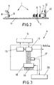
- an opto-electronic system is conventionally known to inspect the state of wear of the overhead distribution of a railway track, that is installed in one of the cars of the train and that bases its operation on the use of laser beams that fall upon the bottom part of the cable or cables of the overhead distribution, on which the pantographs of the locomotives are supported, producing the wear of the cables by friction.
- the laser rays that fall upon said bottom part of the overhead distribution are reflected and captured by some cameras provided with CCD sensors. These cameras automatically focus the overhead distribution, in such a way that the real image thereof is obtained.
- the image captured by the cameras is processed to determine the width of the worn surface, determining the state of the overhead distribution.
- the entire unit is mounted on a car that runs along the path to be inspected, for which purpose on the ceiling of said car an opening has been made through which the lighting and capturing of the image of the cables is made possible.
- optical and lighting subsystems used have a very elaborate and complex structure, that is complemented by the captured image processing subsystem, which, though complex, is simpler.
- This structure determines greater difficulty, when the future expansion of the system for subsequent modifications is put forth, aside from the fact that the optical subsystem turns out to be more expensive than what is really needed to carry out the measurement of the width of the wear of the cable of the overhead distribution.
- Article "An Artificial Vision System used for the Measurements of the Overhead Wire in railway Applications” describes a system for measuring the wear of the overhead contact wire of a railway.
- the system is capable of measuring the cross section of the overhead wire without physical contact at high speed (160 km/h), with a rate of error less than 5%.
- the measuring method is based on an artificial vision system.
- the invention is characterized in that its laser lighting subsystem is formed by a plurality of identical modules placed horizontally and sideways to the image capturing cameras, each one of said lighting modules having laser, being comprised of a the laser diode which remains opposite a piano-cylindrical lens that forms the emitted light in a vertical plane.
- plano-cylindrical lens After the plano-cylindrical lens there are two lenses in the horizontal plane that ensure the divergence that is required in this plane.
- the laser emitter there is a third mirror, that remains located in the space between the two above mentioned mirrors, in such a way that the beam of light makes a zigzag optical path guided by the mirrors, for lengthening the optical path so that its size is suitable to light up an area that corresponding to each module; achieving minimum distances between the components of the system so as to obtaina greater use of the space and better compactness of the system.
- the optical path followed by a beam emitted by the laser lighting subsystem is independent from the optical path followed by a beam received by the image capturing subsystem.
- the laser diode is connected to a NTC thermistor and to a Peltier cell.
- the thermistor and the Peltier cell are connected to each other, and in turn they are connected to a temperature control circuit that receives the signals coming the cell and from the thermistor, in such a way that it regulates the temperature of the laser, so that it functions at a constant temperature, since temperature variations during its functioning represent variations in the laser emission wave length, therefore this arrangement allows the emission of the beam of light to be carried out with a constant wave length.
- the laser diode is related to a photo-diode monitor that detects the emitted radiation, and they are connected to a control circuit to control the laser polarization current and therefore the emission strength thereof.
- the image capturing subsystem comprises a plurality of cameras, each one of which faces a first surface mirror that is placed on a support at 45°, in such a way that the images are collected in the horizontal plane.
- the first surface mirrors are placed on the support by means of a material that absorbs vibrations, and besides it has means to adjust the slant thereof, for the purpose of achieving the orientation suited to the capturing of images.
- the lenses are conventional and non-specific which greatly reduces costs.
- the equipment can function when there is no light (at night) or when there is too much (at high noon) without any problems.
- the automatic focusing subsystem is characterized in that it is formed by a D.C. motor capable of being operated manually by means of a remote control or by means of push buttons, to carry out the initial focusing, from which the focusing is done automatically.
- the automatic focusing is controlled by a control circuit, that is connected to the D.C. motor, which in turn is connected to a worm, in such a way that upon activating the motor, a frame, to which a plurality of platforms supporting the cameras are integral, moves.
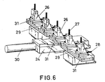
- Each one of said platforms is mounted on an individual carriage capable of being operated by hand by means of a plurality of positioning controls in three axis, in such a way that it enables adjustment of the optical capturing subsystem slightly overlapping the fields of vision of the cameras, upon activating the individual positioning controls in each one of the three axis of each one of the cameras.
- a mixed analogic/digital loop for controlling a position of the motor (45) comprises:
- the analogic control loop is formed by a differential encoder that in turn is connected to the motor, generating pulses when the motor turns, in such a way that it indicates the relative position of the frame with regard to the initial focus obtained manually.
- the differential encoder is connected to the detector (47), said detector (47) being connected to two inputs of the meter (49), wherein the calculated signal has been previously loaded after carrying out an initial focusing, so as to obtain in the meter (49) output a signal proportional to a position the motor has with regard to an initial position of the frame, said signal being applied to an input of the digital/analog converter (50) with an output connected to the first input of the comparator (52), which receives the on the second input an analogic signal of a distance between the camera lens (62) and the CCD sensor in each moment, the comparator (52) providing a difference signal that, after passing through the adjuster (51) and the compensator of dead spots (43), is applied as a speed signal to the direct current/direct current converter (44) for controlling rotation of the motor (45) so as to position the frame in a suitable point to focus.
- connection of the detector of the direction of rotation of the motor, to the clock of the meter is done by means of a divider, considering that the field depth of the cameras does not have to be very precise in the signal coming from the analogic loop, in this way a resolution of positioning resolution more suitable to the field depth of the camera is obtained, simplifying the digital/analogic converter connected to the comparator output.
- the feed subsystem of the different subsystems that comprise the invention is defined by a plurality of voltage sources, that from the line voltage different voltages of operation are furnished for the subsystems of the invention.
- Each one of the voltage sources is connected to a network by means of suitable filters, a voltage sources control circuit (56) and to a supervision circuit (57), the voltage sources control circuit (56) and the supervision circuit (57) being connected to a state memorizing circuit (58), that in turn is connected to a time starting circuit (59) and to a display (60); so as to upon connecting the feed subsystem, a temporized initiation be produced during which the sources (55) do not have output voltages to avoid initial transient from influencing said output, after carrying out the initiation, the voltage sources be activated and a period of time afterwards, the supervision circuit, for ensuring that the supervision circuit functions when all the voltages are established, deactivate all voltage sources if an anomaly is produced in one of the voltage sources, all incidences being indicated optically.
- Some of the voltage sources, and more specifically those used for the laser lighting subsystem require a sequential start to be carried out, for which purpose the source control circuit is connected to a sequential starting circuit, which in turn is connected to the voltage sources that must function with this type of start, each one of these sources being connected to the source supervision circuit that is connected to the state memory , correctly controlling the sequential starting of these sources.
- this processing subsystem is defined by a plurality of transputers that operate in bridge, and that are connected to a personal computer for communication with the operator.
- connection lines with the personal computer is divided in four image processing levels.
- the first level is comprised by the detection of images of each camera whose task is to detect the possible impressions and to send to the next level only the portion of the image that contains them.
- the second level carries out the measurement of the detected impressions and is comprised of a number of modules lower than the number of modules used in the first level.
- Each measuring module of the first level communicates with two modules of the second level, with the particularity that the end modules of the first level are communicated with two of the second level, the ones farthest apart from each other.
- the communication of the first level with the second level uses the most direct communication line, except when said line is busy, a circumstance that makes it necessary to use another line, which is the one farthest away, which causes better usage of the transputers, since when the impression is in an end, normally there is no impression in the other one, thus the transputer corresponding to this end is normally inactive. In this way, the speed and capacity of the system are increased.
- the third level is of composition and it classifies the data processed in the previous level, since in the previous level as well as in the first one, the operations are carried out in any order to obtain greater processing speed, and the data is sent as soon as it is ready wherever it is possible to do so, therefore, the data arrives out of order in space and time.
- the reclassification is possible thanks to the information that accompanies the measurements. In this way, at the output of the third level, the measurements have a fixed format and are perfectly in order.
- the fourth level is comprised by making the history and supervision control as well as the control of the entire network, this level being the only one that communicates with personal computer.
- the fourth level is also responsible for setting off the cameras and monitoring the mistakes that could have been produced during transmission, errors that have to be corrected. Besides, it classifies all the operations to be carried out with the external devices, with the personal computer as well as with the cameras, table, focusing, gates, etc. Besides, it is responsible for storing in the hard disk and of the interface with the user; graphic outputs, alarms keyboard control.
- the personal computer acts as a mere intelligent peripheral and is connected to the network by means of a serial/parallel interface.
- the task of the personal computer consists of providing the system with resources such as the handling of the disks, graphic display and the keyboard.
- resources such as the handling of the disks, graphic display and the keyboard.
- a program that carries out two tasks runs in it: initially it loads each transputer with the corresponding program; then it manages all the requests of the network.
- the image processing subsystem acts independently from the speed of the car in which it is installed always taking the same number of images per second; said number of images being available to be varied so as to obtain a desired number of images per unit of length.
- the processing subsystem is connected to some auxiliary peripherals comprised of a digital/analogic converter that receives the measurement of height, to some link buffers of the cameras, to the digital/analogic converter for self-focusing, and to a Telec point meter.
- the height of the contact wire that supplies the operating voltage of the train It is essential to know the height for two reasons: the first one is the apparent size of objects varies with distance and the second one is that the overlapping of cameras also varies. To know the real size of an impression and in order to distinguish which of them are doubles of other ones for each shoot it must be accompanied by the height of the contact wire that supplies the operating voltage of the train.
- the measurement of the real impression of the overhead distribution of an entire path is obtained, associated to the position thereof on the track, making graphs of said impression with regard to said position, which determines the impression existing in the overhead distribution of an entire path it being possible to make forecasts regarding replacement of the cable.
- the measuring system of the wear of the overhead distribution contact wires of the invention is especially applicable to determine the wear of the wires of the overhead distribution of railway lines, for which reason it is of the type that is based on the principle of obtaining, by quasi-regular reflection of the optical image of the impression of the contact wire.
- the visualization of the edges of the impression in other words, the width thereof, is perfect, since the change of curvature in the cross-section of the wires of the overhead distribution is taken advantage of.
- a laser ray emitting subsystem (4) that is comprised of a series of identical modules that are located sideways to the image capturing optical system (2) is used.
- the focusing of the optical image capturing subsystem (2) is done automatically, processing the captured image by means of a processing subsystem, to determine the width of the worn surface.
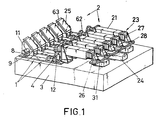
- the optical image capturing system (2) as well as the laser lighting subsystem (1) and the automatic focusing subsystem are mounted on an optical table (3) that remains located inside the car.
- Said table remains placed horizontally and located under a groove made in the ceiling, in order to allow lighting and obtainment of the image of the overhead distribution, just as it will be described hereinafter.
- the laser lighting subsystem (1) is comprised of six identical modules placed sideways to the optical image capturing subsystem (2), which is defined by five identical modules.
- the number of modules can vary in terms of the needs.
- Each one of the modules that comprise the laser lighting subsystem includes as a light source (4) a laser diode (13) of 500 mW of maximum emitting power at a central emission frequency, at 25° C, around 810 nm, in a band width of 2nm.
- the radiation emitted by the laser diode (13) is concentrated by a first converging plano-spherical lens (5), that reduces the output divergences by about 50%, thus making it possible to make use of almost all of the power of the radiated light.
- the beam of light emerging from the converging plano-spherical lenses (5) is formed on the vertical plane by means of a positive plano-cylindrical lens, which remains located in such a way that the beam that emerges from it has the least possible divergence.
- the optical path followed by a beam emitted by the laser lighting subsystem (1) is independent from the optical path followed by a beam received by the image capturing subsystem (2).
- the lenses (7) that ensure the required horizontal divergence are placed on the horizontal plane.
- a frame (12) that supports a mirror (10), in such a way that the beam of light falls on the mirror (9) and is reflected towards mirror (10) from which it is reflected towards mirror (11), following a zigzag optical path, for lengthening the optical path so that its "horizontal size" (which is crosswise after mirror (11)) is the suitable one to light up the area that corresponds to each module; achieving minimum distances between components of the system so as to obtain a better use of space.
- Each module, with its card constitutes a complete unit that can be moved from its housing on the table for repair, adjustment, etc.
- This entire unit remains placed on a frame (14) that is fastened to the optical table (3).
- the laser diode itself (13), already commented on above, is connected to a photo-diode monitor (15) that is placed in the rear part of the unit (4) and it detects about 10% of the useful radiation emitted by the laser, in such a way that by means of the detection carried out it is possible to control the polarization current of the laser diode through an electronic control circuit (16), which in turn is connected to the laser diode (13) to control the emission power thereof.
- the laser matrix (13) is mounted on a Peltier cell (18) which combined with a NTC thermistor (17), that carries out temperature sensor functions, allows the laser diode to operate at a constant temperature, by means of an external temperature control circuit (20).
- This operating temperature control is very important when the matrix is used in applications where a very refined wave length value is required, such as in the present case, due to the fact that the wave length varies with temperature. It is estimated that the wave length variation in terms of temperature is around 0.2 to 0.3 nm/°C.
- the NTC thermistor (17) with the Peltier cell (18) define a refed system that allows the setting of the connection temperature independently from the value of emitted power or outside temperature.
- the Peltier cell is a thermoelectric device that acts like a reversible heat pump, in other words, it cools or heats depending on the direction of the current that passes through it.
- a liquid crystal display for showing temperature indicates an operating temperature of each diode. Due to the delicate construction process between laser diodes, it is very difficult to make two alike, therefore, the electric characteristics vary from one diode to another, thus the current and the voltage that must be applied to leach laser varies, thus, it is necessary to gauge each one independently, it not being possible to exchange them once the gauging has taken place.
- the power control is done by current control, since the power emitted is proportional to the injected current.
- the basic power control circuit is comprised of an adjustable current source; likewise a liquid crystal display for showing power indicates an operating power of each diode.
- the optical image capturing subsystem (2) is described hereinafter.
- the optical image capturing subsystem is formed by five identical modules whose optical axes are separated 200 nm from each other.
- Each module is basically defined by a conventional high speed photographic camera, provided with a conventional lens and a CCD sensor.
- the optical axis is placed horizontally and is directed vertically by a first surface mirror(25)inclined 45°.
- the first surface mirrors (25) are placed on a support (63), which upon being close to the lens, a small variation in its position greatly influences the location of the "object". For this reason the support (63) is especially strong and the same can include fine adjustment of the mirror in the two axes by means of screws.
- the mirror-support connection is sealed with silicone to prevent undesired relative movements. In any case the permanent elasticity of this sealing with silicone allows any subsequent small readjustment of the mirror.
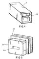
- the lens (62) remains fastened and after it, given its large viewing angle, there is an optical labyrinth (21) especially designed and built for this use, by means of which it guarantees that only the light that passes through the lens and that comes from the object reaches the CCD sensor without it being possible to capture light, that through the lens, comes from areas that do not correspond to the object.
- this "object” is the image that of the CCD given by the lens in the object plane that, at the nominal height is a horizontal crosswise to the track axis.
- the labyrinths rest on the same support as the lenses and are painted inside and outside with dull lamp black color paint.
- the light coming from the labyrinths (21) comes out through a groove (32) made in the rear part.
- the interferential filters (23) are not interchangeable and if their positions are altered it is necessary to readjust the adjacent lasers.
- the CCD sensors have associated the 'electronics corresponding to the control of the module and matching of the signals supplied by the module to the image processors defined by transputers that will be described hereinafter. Likewise, it includes a module feed supervision system.
- This structure allows the system to function during the day or at night indistinctly.
- the optical resolution is defined as: that which determines the relation of size between object and image.
- the distance between the object and the lens P is the height of the contact wire, therefore it is necessary to determine said height, which is done by a peripheral as it will be described hereinafter.
- the distance between the lens and image, P' is the distance from the lens to the CCD sensor. To maintain a correct focus, for each distance P between the contact wire and the lens, it is necessary to position the CCD cameras of the lenses at their corresponding distance P' .
- the problem is posed of mechanically positioning the CCD cameras at the suitable distance from the lens.
- the mechanical part of this focusing system has been represented in figure 6 and which is comprised by a frame (24) placed in a center position on the optical table, that includes a worm (30) that is activated by a continuous current motor.
- Some platforms (31) have been provided for on the frame (24): two side ones and a center one, that are coupled together, in such a way that single movement according to axis Z is made possible.
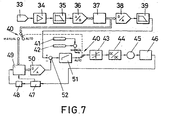
- figure 7 With regard to the electronic control of the self-focusing system, its block diagram has been represented in figure 7 that is comprised of the peripheral that determines the height of the contact wire and more specifically the distance between it and the lenses, which is represented by module (33), that is connected to an amplifier (34) and the latter to a filter (35) whose output is applied to a digital/analog converter (36) which in turned applied to an EPROM from which the distance from the CCD to the lenses is obtained with a digital value, a signal that is converted into analogic by means of the converter (38) and conveniently filtered by module (39).
- module (33) that is connected to an amplifier (34) and the latter to a filter (35) whose output is applied to a digital/analog converter (36) which in turned applied to an EPROM from which the distance from the CCD to the lenses is obtained with a digital value, a signal that is converted into analogic by means of the converter (38) and conveniently filtered by module (39).
- the signal coming from the filter (39) is applied to a comparator (52) whose output is applied to a regulator (51) that after a switch (40) by means of which it goes from the manual focusing position to the automatic focusing one, it is applied to the motor (45) through a compensator of the dead spots (43) of the motor and of a converter of continuous current to continuous current (44).
- the output of the motor (45) is applied to an encoder (46) and this is in turn applied to a detector of the direction of rotation (47) which is connected to the ascending-descending count input of a meter (49) and to the clock input of the meter, by means of a divider (48).
- the meter (49) is connected by a switch (40), that determines the automatic or manual operating position to the memory (37) output.
- a first part that positions the focusing table in a specific reference point.
- the real position of the table is attained by means of the encoder (46) that is incremental and not absolute, therefore the positioning of the table is relative to its original location, which is understood to be the position of the table when the control loop is open, which is the same as indicating that we are in manual mode; and consequently without position adjustment which would correspond to the automatic mode.
- the second part is comprised by the generation of this reference point that corresponds to the solution of the optical equation, where the table must be positioned.
- the adjustment loop works with the signal coming from the filter (39), as the position recognition signal and the signal coming from the digital/analog converter (50), which is the real position signal of the focusing table.
- the signal coming from the filter (39) is generated in terms of the height of the contact wire; while the signal coming from the digital/analog converter (50) is calculated by counting the pulses provided by the incremental encoder (46) that is placed in the shaft of the motor (45), which moves the frame (24) that has also been named in this memory table.
- the output of the incremental encoder (46) is applied to a detector of the direction of rotation (47), in such a way that it indicates to the meter (49) that carries out an ascending or descending count, on the initial value in storage through its load input after positioning in the switch (40) in the manual position, whereby the signal coming from the memory (37) is stored in the same.
- the output of the detector of the direction of rotation (47) is applied to the clock input by means of a divisor by 16, this is due to the fact that the incremental encoder (46) provides a pulse/ ⁇ m, and if this output were used directly, we would obtain with it positioning solutions in the neighborhood of one ⁇ m, with which it would be necessary to use analog/digital and digital/analog converters (50) of many bits.
- the table is positioned with a precision of 16 ⁇ m.
- the pulse output of the encoder is divided by 16. In this way the necessary converters need many less bits, greatly simplifying the structure thereof.
- the detection of the direction of rotation is done by means of a relatively complicated circuit. ⁇ Due to the position of the encoder (46), in the stopping point of the motor (45) (stop due to the adjustment loop, not a stop due to feed disconnection in the terminals of the same), transitory pulses can be produced which are to be taken into account thus said circuit has been designed as a sequential nonsynchronous-synchronized circuit and implemented in a PAL.
- the difference between the real position and the reference position signals determine an error signal, which is introduced in the adjuster (51) obtaining at the output of the same the control signal, in speed, that attacks the continuous current converter to continuous current (44) that governs the motor (45.) Due to the dead spot that the motor has, the output of the adjuster (51) passes through a block that compensates said effect, obtaining at the output of the same the speed recognition signal that really attacks the continuous current converter to continuous current (44).
- the analogic signal that represents the contact wirelens distance is digitized in the converter (36) that represents the distance P.
- This digital signal directs a memory position in the EPROM (37), where it is recorded, the value that must take the distance between the object and the CCD, P'.
- This data corresponds to the solution of the above mentioned optical equation, and it is taken as the reference position for the optical table.
- the reference signal is obtained in the analogic manner, signal that is used as a recognition in the positioning loop.
- Reference (41) represents manual control and reference (42) represents the reference provided by the personal computer connected to the transputers of the image processing system, that will be described later on.
- the reference position value determined at the output of the EPROM (37) is loaded in the meter (49) that measures the table position. In this way it is ensured that the control loop starts from a correct position.
- the error signal at that moment is null since the signals applied to the comparator (52) have the same voltage, and when the loop -closes (automatic position), the incremental positioning control is carried out with regard to the position established manually.
- Manual movement of the table can be done from the personal computer itself established by the input (42) or from an external control, established by the input (41), that consists of four push buttons for advancing in both directions slowly and rapidly.
- the self-focusing control circuit uses a mixed analogic/digital loop to control the position of the motor (45); by means of a circuit based on EPROM (37) carries out a digital calculation of a reference position of the distance from a contact wire to the lens (62). from which the distance that must exist between the lens and the CCD sensor is calculated; compares this signal with the signal of the loop; generates a difference signal that acts upon the motor (45) forcing both compared signals to be equal, whereby the frame (24) is correctly placed in order to achieve automatic focusing.
- the feed subsystem is comprised of a series of sources (55) that are connected to the network by means of the corresponding filter.
- Each one of these sources (55) is connected to a control circuit (56) a supervision circuit (57), these two being connected to a state memorizing circuit (58) that in turn is connected to a time starting circuit (59) and to a display (60).
- the timed starting circuit (59) has two outputs (53) and (54).
- Signal (53) is used to adjust to zero the memory (58) of the state of the sources, therefore all the sources are connected to a voltage of 220 volts, the output thereof remaining inhibited. In this way it is prevented that the transitory one, due to the connection of the transformers, influences the output of the sources.
- the supervision system (57) informs about the state of the sources from the first moment, therefore the visualization (60) will be of failure of all the pilot lights, for example red ones (lack of voltage).
- the source control (56) activates each one of them simultaneously or by means of the sequential starting block (61), that will be described hereinafter.
- the visualization system indicates the correct starting of the sources, the pilot lights turning green for example.
- the second control signal (54) activates the protection system for example 0.5 s after establishing all the voltages, in such a way that if any of the voltages is not present or fails later on, the anomaly is memorized and all the sources are immediately turned off. Then one can see in the display the source causing the error in red color and the rest remains green.
- the source (55) corresponding to the indicated subsystem is governed from the source feed circuit (56) through a sequential starting circuit (61), producing the sequential starting control of the source.
- This subsystem is comprised of a series of transputers that have been connected forming five lines, that converge in the personal computer.
- Each line is divided into four numbered image processing levels.
- the first level carries out the detection of the images of each camera, and its task consists of determining the possible impressions and sending to the next level only the portion of the image that contains them.
- the second level carries out the measurement of the impression and it is formed by four modules, unlike the first level that is comprised of five.
- the number of modules of this level is smaller since the total image has been reduced eliminating the portions that do not contain the impression.
- Each first level module is communicated with two of the second level the farthest away from each other as possible.
- the first level module of one end is connected to the module of the same end and that of the other end of the second module.
- the processing line will normally be more direct, but if the corresponding transputer is busy measuring an impression, another line is used. Going on with this example, given that when the impression is in one end the normal thing is that there is nothing in the other end.
- a transputer which would otherwise be under-used, is taken advantage of. In this way, together with the performance of the transputers, the speed and capacity of the system is increased.
- Level three carries out the composition of the measures taken and only the measurements of the impressions that have been detected reach it: only the first two levels work directly with pixels. In the two bottom levels the order of the data is not taken into account, to achieve maximum speed, the results are sent as soon as they are ready wherever it is possible to do so. Therefore they arrive out of order spatially and in time. Thanks to the information that accompanies the measurements it is possible to reclassify them and to change them to an absolute reference (up to now they have had a relative reference to the camera to which they belong.) At the output, the measurements have a fixed format and are perfectly classified.
- the fourth level is comprised of the history and control level and it controls the entire network and supervises the conveyance of the data through the same. It is formed by a single transputer which is the master of the system.
- the network have several states according to the task that is being carried out. Going from one to another is done by the messages that are sent from here and that are distributed along the entire network. It is also responsible for setting off the cameras and monitoring the errors that could be produced during transmission and it is responsible for correcting them. It orders all the operations without external devices, with the personal computer as well as with cameras, focusing table, height converter, gates, etc.
- This transputer is the only one that communicates directly with the personal computer, therefore it is responsible for the storage in hard disk and interface with the user: graphic outputs, alarms and keyboard control.
- the personal computer acts as a mere intelligent peripheral. It is connected to the network by means of the serial/parallel interface and its task is to provide to the system resources such as management of disks, graphic display and keyboard. For this purpose, a program that carries out two tasks runs in it: initially it loads each transputer with the corresponding program, then it attends to the requests of the network.
- the fourth level does not directly manage the peripherals developed for the system, which consist of the Telec point detector, measured from the height of the overhead distribution, number of contact wires among others.
- the image processing subsystem acts independently from the speed of the car in which it is installed always taking the same number of images per second; said number of images being available to be varied so as to obtain a desired number of images per unit of length.
- the image processing subsystem is connected to a plurality of auxiliary peripherals comprised of an analog/digital converter for receiving a measurement of height a plurality of link buffers of the CCD cameras; a digital/analog converter for self-focusing; a Telec point meter, so as to obtain a real impression associated to a position on the track.
- auxiliary peripherals comprised of an analog/digital converter for receiving a measurement of height a plurality of link buffers of the CCD cameras; a digital/analog converter for self-focusing; a Telescope point meter, so as to obtain a real impression associated to a position on the track.
- peripherals are controlled by level (5) with a weaker transputer, but that makes it possible to go from any format to the standard link and, in turn, to unload the master transputer of work.
- level (5) with a weaker transputer, but that makes it possible to go from any format to the standard link and, in turn, to unload the master transputer of work.
- the fourth level gives orders and the fifth level carries them out.
- the fifth management level of inputs/outputs for managing the peripherals is included in an image processing subsystem.
- Another one of the peripheral connected to the personal computer is comprised by the link buffer which is designed to work in calm electromagnetic environments, that is to way without noise and interference.
- the functionality of the model based on transputers depends on the infallibility of these links, since it is not foreseen that they try again a communication that has failed.
- At the card level it is not necessary to use exciters, but it is necessary to do so for remote communications of meters, about all in environments as noisy as a train.
Landscapes
- Physics & Mathematics (AREA)
- General Physics & Mathematics (AREA)
- Length Measuring Devices By Optical Means (AREA)
- Length Measuring Devices With Unspecified Measuring Means (AREA)
- Investigating Or Analyzing Materials By The Use Of Magnetic Means (AREA)
- Measurement Of Length, Angles, Or The Like Using Electric Or Magnetic Means (AREA)
Claims (13)
- Automatisches Messsystem zum Messen des Verschleißes von Fahrleitungsdrähten von dem Typ, der auf Eisenbahnstrecken verwendet wird,
bei dem Laserstrahlen verwendet werden, die auf einen unteren Teil wenigstens eines Kabels der Fahrleitung fallen, an dem Stromabnehmer von Lokomotiven aufliegen und an dem die Laserstrahlen reflektiert werden;
wobei die Laserstrahlen von einer Vielzahl von Kameras erfasst werden, die in einem Bilderfassungssystem (2) installiert sind, und die Kameras mit CCD-Sensoren und Kameraobjektiven (62) versehen sind;
die CCD-Kameras mittels eines automatischen Fokussier-Teilsystems automatisch auf die Fahrleitung fokussieren;
ein Bildbearbeitungs-Teilsystem ein erfasstes Bild verarbeitet, um die Breite einer Verschleißfläche zu bestimmen;
das System an einem Wagen angebracht ist, der auf einem zu prüfenden Weg entlang fährt, wobei ein Loch in der Decke des Wagens ausgebildet ist, um Beleuchtung und Erfassung des Bildes des wenigstens einen Kabels zu ermöglichen;
ein Laserbeleuchtungs-Teilsystem (1) eine Vielzahl identischer Module umfasst, die horizontal an Seiten der CCD-Kameras angeordnet sind;
jedes Modul aus einer Laserdiode (13) besteht, deren Emission von Licht auf einer vertikalen Ebene mittels einer planzylindrischen Sammellinse (7) erzeugt wird, auf die zwei Linsen (7) in einer horizontalen Ebene folgen, um Streuung zu gewährleisten, die in der Ebene erforderlich ist;
ein Strahl, der von dem Laserbeleuchtungs-Teilsystem (1) emittiert wird, einem Lichtweg folgt, der unabhängig von einem Lichtweg ist, dem ein Strahl folgt, der von dem Bilderfassungs-Teilsystem (2) empfangen wird;
dadurch gekennzeichnet, dass das Bilderfassungs-Tellsystem (2) umfasst:wobeieine Vielzahl von CCD-Kameras;eine Vielzahl erster Oberflächenspiegel (25);
sich jede CCD-Kamera gegenüber jedem ersten Oberflächenspiegel (25) befindet;
jeder erste Oberflächenspiegel (25) auf einer Auflage (63) in 45° auf einem Material angeordnet ist, die versehen ist mit:wobei jede CCD-Kamera versehen ist mit:einer Dämpfungseinrichtung zum Absorbieren von Schwingungen; undeiner Einstelleinrichtung, die anschließende Feineinstellungen ermöglicht,einem Labyrinth (21) zwischen dem Kameraobjektiv (62) und dem CCD-Sensor, das gewährleistet, dass Licht, das zu dem CCD-Sensor gelangt, von dem Kameraobjektiv (62) kommt, ohne dass es möglich ist, das anderes verfügbares Licht zu ihm gelangt;eine Vielzahl von Interferenzfiltern (23) zwischen dem Labyrinth (21) und dem CCD-Sensor, die nur Strahlung, die in einem Durchlassband derselben enthalten ist, zu dem Sensor gelangen lässt, wobei die Strahlung für jede Kamera spezifisch ist. - Automatisches Messsystem nach Anspruch 1, dadurch gekennzeichnet, dass ein Strahl, der von den zwei Linsen (7) projiziert wird, von Spiegeln (9, 10, 11) geführt, einem Zickzack-Lichtweg folgt, um:den Lichtweg zu verlängern, so dass seine Größe sich dazu eignet, einen Bereich zu beleuchten, der jedem Modul entspricht;minimale Abstände zwischen Komponenten des Systems zu erzielen, um so eine bessere Nutzung des Raums zu erreichen.
- Automatisches Messsystem nach Anspruch 1, dadurch gekennzeichnet, dass das automatische Fokussier-Teilsystem einen Gleichstrommotor (45) umfasst, der:wobei jede der Plattformen (31) an einem einzelnen Schlitten (26) angebracht ist, der von Hand mittels einer Vielzahl von Posltionier-Bedienelementen (27, 28, 29) zur anfänglichen Einstellung in drei Achsen betätigt werden kann, um:von Hand oder automatisch von einer Steuerschaltung betrieben werden kann,mittels einer Schnecke (30) mit einem Rahmen (24) verbunden ist, um den Rahmen (24) zu bewegen, an dem sich eine Vielzahl von Plattformen (31) befindet, die die Kameras tragen,die manuelle oder automatische Ausführung einer anfänglichen Fokussierung zu ermöglichen,ein optisches Erfassungssystem so einzustellen, dass sich die Sichtfelder der Kameras geringfügig überlappen,um dann das Umschalten der Steuerschaltung auf Betrieb zum automatischen Fokussieren gleichzeitig für alle Kameras zu ermöglichen.
- Automatisches Messsystem nach Anspruch 3, dadurch gekennzeichnet, dass das automatische Fokussier-Teilsystem eine gemischte Analog/Digital-Schleife zum Steuern einer Position des Motors (45) umfasst, wobei die Steuerschaltung umfasst:eine auf EPROM (37) basierende Schaltung, die eine Berechnungseinrichtung zum digitalen Berechnen einer Bezugsposition eines Abstandes zwischen einem Fahrleitungsdraht und einem Kameraobjektiv (62) enthält, anhand der ein Abstand zwischen dem Kameraobjektiv (62) und dem CCD-Sensor berechnet wird, so dass ein berechnetes Signal bereitgestellt wird;eine Vergleichseinrichtung zum Vergleichen des berechneten Signals mit einem gemessenen Signal, das von einer Messeinrichtung bereitgestellt wird;eine Subtrahiereinrichtung, die ein Differenzsignal erzeugt, das durch Subtrahieren des gemessenen Signals von dem berechneten Signal entsteht;eine Einrichtung zum Anlegen des Differenzsignals an den Motor (45), wobei beide verglichenen Signale, d.h. das berechnete Signal und das gemessene Signal, gezwungen werden, gleich zu sein, so dass der Rahmen (24) richtig zum automatischen Fokussieren angeordnet wird.
- Automatisches Messsystem nach Anspruch 4, dadurch gekennzeichnet, dass die gemischte Analog/Digital-Schleife umfasst:wobei der Differenzkodierer (46) aufweist:eine Kompensationseinrichtung für Totpunkte (43) des Motors (45);einen Gleichstromumrichter (44) des Motors (45);einen Differenzkodierer (46);einen Detektor (47) für die Drehrichtung des Motors (45);eine Messeinrichtung (49), die versehen ist mit:zwei Eingängen, einem Aufwärts-Abwärts-Zähl-Steuereingang und einem Takteingang;einem Ausgang;einen Digital-/Analog-Wandler (50);eine Einstellvorrichtung (51);einen Komparator (52), der mit einem ersten Eingang und einem zweiten Eingang versehen ist;einen Eingang, der mit dem Motor (45) verbunden ist, so dass Impulse erzeugt werden, wenn sich der Motor dreht, um die relative Position des Rahmens (24) in Bezug auf eine anfängliche Fokusposition anzuzeigen, die manuell erreicht wird;einen Ausgang, der mit dem Detektor (47) verbunden ist, wobei der Detektor (47) mit zwei Eingängen verbunden ist von:der Messeinrichtung (49), wobei das berechnete Signal im Voraus geladen worden ist, nachdem eine anfängliche Fokussierung durchgeführt wurde, um so am Ausgang der Messeinrichtung (49) ein Signal zu erreichen, das proportional zu einer Position ist, die der Motor in Bezug auf eine Anfangsposition des Rahmens hat, wobei das Signal angelegt wird an einen Ausgang des:Digital-/Analog-Wandlers (50) mit einem Ausgang, der verbunden ist mit dem ersten Eingang des:Komparators (52), der an dem zweiten Eingang ein analoges Signal eines Abstandes zwischen dem Kameraobjektiv (62) und dem CCD-Sensor in jedem Moment empfängt, wobei der Komparator (52) ein Differenzsignal bereitstellt, das, nachdem es durch die Einstelleinrichtung (51) und die Kompensationseinrichtung für tote Punkte (42) hindurchgeleitet wurde, als ein Geschwindigkeitssignal angelegt wird an:den Gleichstromumrichter (44), um Drehung des Motors (45) so zu steuern, dass der Rahmen an einem geeigneten Fokuspunkt positioniert wird.
- Automatisches Messsystem nach Anspruch 1, dadurch gekennzeichnet, dass ein Speise-Teilsystem umfasst:eine Vielzahl von Spannungsquellen (55), die verbunden sind mit:so dass:einem Netz mittels geeigneter Filter,einer Spannungsquellen-Steuerschaltung (56) und miteiner Überwachungsschaltung (57), wobei die Spannungsquellen-Steuerschaltung (56) und die Überwachungsschaltung (57) verbunden sind mit:einer Zustands-Speicherschaltung (58), die ihrerseits verbunden ist mit:einer Zeit-Anfangsschaltung (59) und mit:einer Anzeigeeinrichtung (60);beim Verbinden des Speise-Teilsystems eine zeitlich begrenzte Initialisierung erzeugt wird, während der die Quellen (55) keine Ausgangsspannungen haben, um zu verhindern, dass anfänglicher Stoß den Ausgang beeinflusst,nachdem die Initialisierung ausgeführt worden ist, die Spannungsquellen und nach einem Zeitraum danach die Überwachungsschaltung aktiviert werden, um zu gewährleisten, dass die Überwachungsschaltung arbeitet, wenn alle Spannungen hergestellt sind,alle Spannungsquellen deaktiviert werden, wenn eine Anomalie in einer der Spannungsquellen erzeugt wird, wobei alle Vorfälle optisch angezeigt werden.
- Automatisches Messsystem nach Anspruch 6, dadurch gekennzeichnet, dass die Spannungsquellen-Steuerschaltung (56) mit einer Schaltung (61) zum sequentiellen Starten verbunden werden kann, wobei die Schaltung (61) zum sequentiellen Starten mit wenigstens einer Spannungsquelle (55) verbunden werden kann, die nicht mit der Steuerschaltung (56) verbunden ist, um ein sequentielles Starten auszuführen.
- Automatisches Messsystem nach Anspruch 7, dadurch gekennzeichnet, dass ein sequentielles Starten bei dem Laserbeleuchtungs-Teilsystem (1) eingesetzt wird.
- Automatisches Messsystem nach Anspruch 1, dadurch gekennzeichnet, dass das Bildverarbeitungs-Teilsystem
unabhängig von der Geschwindigkeit des Wagens arbeitet, in dem es installiert ist, und stets eine gleiche Anzahl von Bildern pro Sekunde aufnimmt;
wobei die Anzahl von Bildern pro Sekunde, die verfügbar sind, verändert wird, um eine gewünschte Anzahl an Bildern pro Längeneinheit zu erhalten. - Automatisches Messsystem nach Anspruch 1, dadurch gekennzeichnet, dass das Bildverarbeitungs-Teilsystem eine Vielzahl von Transputern umfasst, die in Brückenbetrieb arbeiten und die zur Kommunikation mit einer Bedienungsperson mit einem Personalcomputer verbunden sind, wobei jede Verbindungsleitung in vier Bildverarbeitungsebenen unterteilt ist und die Bildverarbeitungsebenen umfassen:wobei die vierte Ebene die einzige Ebene ist, die mit dem Personal Computer kommuniziert.eine erste Ebene zum Erkennen von Bildern jeder Kamera, wobei ein Teil eines Bildes gelöscht wird, der keine Daten enthält;eine zweite Ebene zum Messen erkannter Daten, wobei die zweite Ebene weniger Transputer als die erste Ebene enthält;eine dritte Aufbereitungsebene zum Klassifizieren von auf der vorangehenden Ebene verarbeiteten Daten, da, um eine größere Verarbeitungsgeschwindigkeit zu erhalten, Daten in jeder beliebigen Reihenfolge auf den vorhergehenden Ebenen verarbeitet werden;eine vierte Ebene zum:Aufzeichnen von Verlauf, Durchführung von Überwachungssteuerung undSteuerung eines gesamten Netzes,
- Automatisches Messsystem nach Anspruch 10, dadurch gekennzeichnet, dass jeder Mess-Transputer der ersten Ebenen mit zwei Transputern der zweiten Ebene in Verbindung steht,
wobei Abschlusstransputer der ersten Ebene mit zwei Transputern der zweiten Ebene in Verbindung stehen, die am weitesten voneinander entfernt sind,
die direkteste Kommunikationsleitung verwendet wird, wenn diese Leitung nicht belegt ist;
ein nicht ausgelasteter Transputer genützt wird, da, wenn sich Daten an einem Ende befinden, sich normalerweise keine Daten am anderen Ende befinden;
wobei mit der Anordnung Geschwindigkeit und Kapazität des System erhöht werden. - Automatisches Messsystem nach Anspruch 10, dadurch gekennzeichnet, dass das Bildverarbeitungs-Teilsystem mit einer Vielzahl von Zusatz-Peripherieeinrichtungen verbunden ist, die umfassen:einen Analog-/Digital-Wandler zum Empfangen einer Höhenmessung;eine Vielzahl von Verknüpfungspuffern der CCD-Kameras;einen Digital-/Analog-Wandler zum automatischen Fokussieren;eine Kilometerpunkt-Messeinrichtung, um Echtzahlendaten im Zusammenhang mit einer Position auf der Strecke zu erhalten.
- Automatisches Messsystem nach Anspruch 10, dadurch gekennzeichnet, dass das Bildverarbeitungs-Teilsystem mit einer fünften Verwaltungsebene von Eingängen/Ausgängen zum Verwalten von Peripherieeinrichtungen versehen ist.
Priority Applications (3)
| Application Number | Priority Date | Filing Date | Title |
|---|---|---|---|
| EP96500022A EP0789258B1 (de) | 1996-02-09 | 1996-02-09 | Automatisches Messsystem für die Abnutzung von Stromdrähten |
| DE69629793T DE69629793D1 (de) | 1996-02-09 | 1996-02-09 | Automatisches Messsystem für die Abnutzung von Stromdrähten |
| AT96500022T ATE249059T1 (de) | 1996-02-09 | 1996-02-09 | Automatisches messsystem für die abnutzung von stromdrähten |
Applications Claiming Priority (1)
| Application Number | Priority Date | Filing Date | Title |
|---|---|---|---|
| EP96500022A EP0789258B1 (de) | 1996-02-09 | 1996-02-09 | Automatisches Messsystem für die Abnutzung von Stromdrähten |
Publications (2)
| Publication Number | Publication Date |
|---|---|
| EP0789258A1 EP0789258A1 (de) | 1997-08-13 |
| EP0789258B1 true EP0789258B1 (de) | 2003-09-03 |
Family
ID=8225492
Family Applications (1)
| Application Number | Title | Priority Date | Filing Date |
|---|---|---|---|
| EP96500022A Expired - Lifetime EP0789258B1 (de) | 1996-02-09 | 1996-02-09 | Automatisches Messsystem für die Abnutzung von Stromdrähten |
Country Status (3)
| Country | Link |
|---|---|
| EP (1) | EP0789258B1 (de) |
| AT (1) | ATE249059T1 (de) |
| DE (1) | DE69629793D1 (de) |
Families Citing this family (10)
| Publication number | Priority date | Publication date | Assignee | Title |
|---|---|---|---|---|
| GB9904927D0 (en) * | 1999-03-04 | 1999-04-28 | Roke Manor Research | Measurement of wear of the overhead power line for railways |
| ITVE20000036A1 (it) * | 2000-07-18 | 2002-01-18 | Tecnogamma S A S Di Zanini E & | Apparecchiatura di rilevamento dei parametri caratteristici di una linea aerea ferrotramviaria. |
| DE10044432A1 (de) * | 2000-09-08 | 2002-04-04 | Siemens Ag | Einrichtung, Verfahren und Verwendung für die automatische Erfassung des Verschleißes der Fahrdrähte von Oberleitungen für elektrisch angetriebene Fahrzeuge |
| DE10114575B4 (de) * | 2001-03-24 | 2006-03-30 | Fraunhofer-Gesellschaft zur Förderung der angewandten Forschung e.V. | Vorrichtung zur Bestimmung der Restdicke wenigstens eines rundlichen Fahrdrahts |
| JP2007271446A (ja) * | 2006-03-31 | 2007-10-18 | Meidensha Corp | 画像処理によるトロリ線摩耗測定装置 |
| WO2011120058A1 (en) * | 2010-03-26 | 2011-09-29 | Johannes Jacobus Coetzer | A calibration device |
| CN107560578B (zh) * | 2017-10-09 | 2024-01-30 | 西安明松电子科技有限公司 | 一种非接触式激光铁路接触网检测装置及方法 |
| CN112461761A (zh) * | 2020-11-18 | 2021-03-09 | 湖州辰丰线缆有限公司 | 一种线缆自动检测装置及检测方法 |
| CN113155037B (zh) * | 2021-04-29 | 2025-07-04 | 成都华聪智视科技有限公司 | 一种接触线检测装置及接触线检测方法 |
| CN117197700B (zh) * | 2023-11-07 | 2024-01-26 | 成都中轨轨道设备有限公司 | 智能化无人巡检接触网缺陷识别系统 |
-
1996
- 1996-02-09 DE DE69629793T patent/DE69629793D1/de not_active Expired - Lifetime
- 1996-02-09 AT AT96500022T patent/ATE249059T1/de not_active IP Right Cessation
- 1996-02-09 EP EP96500022A patent/EP0789258B1/de not_active Expired - Lifetime
Also Published As
| Publication number | Publication date |
|---|---|
| EP0789258A1 (de) | 1997-08-13 |
| DE69629793D1 (de) | 2003-10-09 |
| ATE249059T1 (de) | 2003-09-15 |
Similar Documents
| Publication | Publication Date | Title |
|---|---|---|
| ES2948448T3 (es) | Localización de datos de sensor recopilados durante la fabricación aditiva | |
| US3864039A (en) | Rail gage apparatus | |
| KR101735576B1 (ko) | 입자 검출기에 대한 향상 | |
| EP0789258B1 (de) | Automatisches Messsystem für die Abnutzung von Stromdrähten | |
| EP1305182B1 (de) | Messverfahren zur messung der eigenschaften eines oberleitungskabels für eisenbahn oder strassenbahn | |
| EP0532169B1 (de) | Optische Prüfsonde | |
| CA2887214A1 (en) | Apparatus and method for determining the target position deviation of two bodies | |
| US7221437B1 (en) | Method and apparatus for measuring distances using light | |
| WO1981003698A1 (en) | Method and apparatus for monitoring movement | |
| NL8000561A (nl) | Werkwijze voor het meten van afstanden en een inrichting voor het uitvoeren van de werkwijze. | |
| CN110146159B (zh) | 一种tof光投射模块的光功率检测装置和方法 | |
| GB1521263A (en) | Electro-optical position monitoring and control means | |
| KR20220037922A (ko) | 3차원 이미지 획득 장치 | |
| US20230384428A1 (en) | Laser-safety control for lidar applications | |
| CN119472801A (zh) | 吸热器上的能量分布情况检测方法及镜场控制模组 | |
| CN209783873U (zh) | Tof相机杂散光检测装置 | |
| KR20190068039A (ko) | 변위센서를 이용한 스크라이브 장치 및 그것의 동작 방법 | |
| RU2138410C1 (ru) | Устройство для измерения износа контактного провода | |
| CN114249214A (zh) | ToF电梯光幕装置、电梯和操作方法 | |
| US20030202173A1 (en) | System and method for measuring the quality of an illumination field from a laser line illumination system | |
| JPH03171401A (ja) | 磁気ヘツド位置測定装置 | |
| US20240248283A1 (en) | Lens Assembly and Thermal Correction for Machine Vision System | |
| RU2174214C2 (ru) | Устройство для контроля износа контактного провода | |
| CN120063146A (zh) | 基于激光散斑的桥梁微形变非接触测量系统及测量方法 | |
| SU1479821A2 (ru) | Устройство дл контрол линейных размеров |
Legal Events
| Date | Code | Title | Description |
|---|---|---|---|
| PUAI | Public reference made under article 153(3) epc to a published international application that has entered the european phase |
Free format text: ORIGINAL CODE: 0009012 |
|
| AK | Designated contracting states |
Kind code of ref document: A1 Designated state(s): AT BE CH DE DK FR GB GR IE IT LI LU NL PT SE |
|
| 17P | Request for examination filed |
Effective date: 19971112 |
|
| 17Q | First examination report despatched |
Effective date: 20010615 |
|
| GRAH | Despatch of communication of intention to grant a patent |
Free format text: ORIGINAL CODE: EPIDOS IGRA |
|
| RAP1 | Party data changed (applicant data changed or rights of an application transferred) |
Owner name: RED NACIONAL DE LOS FERROCARRILES ESPANOLES (RENFE |
|
| GRAS | Grant fee paid |
Free format text: ORIGINAL CODE: EPIDOSNIGR3 |
|
| GRAA | (expected) grant |
Free format text: ORIGINAL CODE: 0009210 |
|
| AK | Designated contracting states |
Kind code of ref document: B1 Designated state(s): AT BE CH DE DK FR GB GR IE IT LI LU NL PT SE |
|
| PG25 | Lapsed in a contracting state [announced via postgrant information from national office to epo] |
Ref country code: NL Free format text: LAPSE BECAUSE OF FAILURE TO SUBMIT A TRANSLATION OF THE DESCRIPTION OR TO PAY THE FEE WITHIN THE PRESCRIBED TIME-LIMIT Effective date: 20030903 Ref country code: LI Free format text: LAPSE BECAUSE OF FAILURE TO SUBMIT A TRANSLATION OF THE DESCRIPTION OR TO PAY THE FEE WITHIN THE PRESCRIBED TIME-LIMIT Effective date: 20030903 Ref country code: CH Free format text: LAPSE BECAUSE OF FAILURE TO SUBMIT A TRANSLATION OF THE DESCRIPTION OR TO PAY THE FEE WITHIN THE PRESCRIBED TIME-LIMIT Effective date: 20030903 Ref country code: AT Free format text: LAPSE BECAUSE OF FAILURE TO SUBMIT A TRANSLATION OF THE DESCRIPTION OR TO PAY THE FEE WITHIN THE PRESCRIBED TIME-LIMIT Effective date: 20030903 |
|
| REG | Reference to a national code |
Ref country code: GB Ref legal event code: FG4D |
|
| REG | Reference to a national code |
Ref country code: CH Ref legal event code: EP |
|
| REF | Corresponds to: |
Ref document number: 69629793 Country of ref document: DE Date of ref document: 20031009 Kind code of ref document: P |
|
| REG | Reference to a national code |
Ref country code: IE Ref legal event code: FG4D |
|
| PG25 | Lapsed in a contracting state [announced via postgrant information from national office to epo] |
Ref country code: SE Free format text: LAPSE BECAUSE OF FAILURE TO SUBMIT A TRANSLATION OF THE DESCRIPTION OR TO PAY THE FEE WITHIN THE PRESCRIBED TIME-LIMIT Effective date: 20031203 Ref country code: GR Free format text: LAPSE BECAUSE OF FAILURE TO SUBMIT A TRANSLATION OF THE DESCRIPTION OR TO PAY THE FEE WITHIN THE PRESCRIBED TIME-LIMIT Effective date: 20031203 Ref country code: DK Free format text: LAPSE BECAUSE OF FAILURE TO SUBMIT A TRANSLATION OF THE DESCRIPTION OR TO PAY THE FEE WITHIN THE PRESCRIBED TIME-LIMIT Effective date: 20031203 |
|
| PG25 | Lapsed in a contracting state [announced via postgrant information from national office to epo] |
Ref country code: DE Free format text: LAPSE BECAUSE OF FAILURE TO SUBMIT A TRANSLATION OF THE DESCRIPTION OR TO PAY THE FEE WITHIN THE PRESCRIBED TIME-LIMIT Effective date: 20031204 |
|
| NLV1 | Nl: lapsed or annulled due to failure to fulfill the requirements of art. 29p and 29m of the patents act | ||
| PG25 | Lapsed in a contracting state [announced via postgrant information from national office to epo] |
Ref country code: PT Free format text: LAPSE BECAUSE OF FAILURE TO SUBMIT A TRANSLATION OF THE DESCRIPTION OR TO PAY THE FEE WITHIN THE PRESCRIBED TIME-LIMIT Effective date: 20040203 |
|
| PG25 | Lapsed in a contracting state [announced via postgrant information from national office to epo] |
Ref country code: LU Free format text: LAPSE BECAUSE OF NON-PAYMENT OF DUE FEES Effective date: 20040209 Ref country code: IE Free format text: LAPSE BECAUSE OF NON-PAYMENT OF DUE FEES Effective date: 20040209 |
|
| REG | Reference to a national code |
Ref country code: CH Ref legal event code: PL |
|
| ET | Fr: translation filed | ||
| PLBE | No opposition filed within time limit |
Free format text: ORIGINAL CODE: 0009261 |
|
| STAA | Information on the status of an ep patent application or granted ep patent |
Free format text: STATUS: NO OPPOSITION FILED WITHIN TIME LIMIT |
|
| 26N | No opposition filed |
Effective date: 20040604 |
|
| REG | Reference to a national code |
Ref country code: IE Ref legal event code: MM4A |
|
| PGFP | Annual fee paid to national office [announced via postgrant information from national office to epo] |
Ref country code: GB Payment date: 20090204 Year of fee payment: 14 |
|
| PGFP | Annual fee paid to national office [announced via postgrant information from national office to epo] |
Ref country code: BE Payment date: 20090227 Year of fee payment: 14 |
|
| PGFP | Annual fee paid to national office [announced via postgrant information from national office to epo] |
Ref country code: IT Payment date: 20090223 Year of fee payment: 14 |
|
| PGFP | Annual fee paid to national office [announced via postgrant information from national office to epo] |
Ref country code: FR Payment date: 20081231 Year of fee payment: 14 |
|
| BERE | Be: lapsed |
Owner name: RED NACIONAL DE LOS FERROCARRILES ESPANOLES *RENFE Effective date: 20100228 |
|
| GBPC | Gb: european patent ceased through non-payment of renewal fee |
Effective date: 20100209 |
|
| REG | Reference to a national code |
Ref country code: FR Ref legal event code: ST Effective date: 20101029 |
|
| PG25 | Lapsed in a contracting state [announced via postgrant information from national office to epo] |
Ref country code: FR Free format text: LAPSE BECAUSE OF NON-PAYMENT OF DUE FEES Effective date: 20100301 |
|
| PG25 | Lapsed in a contracting state [announced via postgrant information from national office to epo] |
Ref country code: BE Free format text: LAPSE BECAUSE OF NON-PAYMENT OF DUE FEES Effective date: 20100228 |
|
| PG25 | Lapsed in a contracting state [announced via postgrant information from national office to epo] |
Ref country code: IT Free format text: LAPSE BECAUSE OF NON-PAYMENT OF DUE FEES Effective date: 20100209 Ref country code: GB Free format text: LAPSE BECAUSE OF NON-PAYMENT OF DUE FEES Effective date: 20100209 |