EP0789139A2 - Combustion engine with flanged generator - Google Patents
Combustion engine with flanged generator Download PDFInfo
- Publication number
- EP0789139A2 EP0789139A2 EP96115093A EP96115093A EP0789139A2 EP 0789139 A2 EP0789139 A2 EP 0789139A2 EP 96115093 A EP96115093 A EP 96115093A EP 96115093 A EP96115093 A EP 96115093A EP 0789139 A2 EP0789139 A2 EP 0789139A2
- Authority
- EP
- European Patent Office
- Prior art keywords
- combustion engine
- internal combustion
- generator
- bearings
- crankshaft
- Prior art date
- Legal status (The legal status is an assumption and is not a legal conclusion. Google has not performed a legal analysis and makes no representation as to the accuracy of the status listed.)
- Granted
Links
Images


Classifications
-
- F—MECHANICAL ENGINEERING; LIGHTING; HEATING; WEAPONS; BLASTING
- F02—COMBUSTION ENGINES; HOT-GAS OR COMBUSTION-PRODUCT ENGINE PLANTS
- F02B—INTERNAL-COMBUSTION PISTON ENGINES; COMBUSTION ENGINES IN GENERAL
- F02B63/00—Adaptations of engines for driving pumps, hand-held tools or electric generators; Portable combinations of engines with engine-driven devices
- F02B63/04—Adaptations of engines for driving pumps, hand-held tools or electric generators; Portable combinations of engines with engine-driven devices for electric generators
-
- B—PERFORMING OPERATIONS; TRANSPORTING
- B60—VEHICLES IN GENERAL
- B60K—ARRANGEMENT OR MOUNTING OF PROPULSION UNITS OR OF TRANSMISSIONS IN VEHICLES; ARRANGEMENT OR MOUNTING OF PLURAL DIVERSE PRIME-MOVERS IN VEHICLES; AUXILIARY DRIVES FOR VEHICLES; INSTRUMENTATION OR DASHBOARDS FOR VEHICLES; ARRANGEMENTS IN CONNECTION WITH COOLING, AIR INTAKE, GAS EXHAUST OR FUEL SUPPLY OF PROPULSION UNITS IN VEHICLES
- B60K5/00—Arrangement or mounting of internal-combustion or jet-propulsion units
- B60K5/12—Arrangement of engine supports
-
- F—MECHANICAL ENGINEERING; LIGHTING; HEATING; WEAPONS; BLASTING
- F01—MACHINES OR ENGINES IN GENERAL; ENGINE PLANTS IN GENERAL; STEAM ENGINES
- F01M—LUBRICATING OF MACHINES OR ENGINES IN GENERAL; LUBRICATING INTERNAL COMBUSTION ENGINES; CRANKCASE VENTILATING
- F01M11/00—Component parts, details or accessories, not provided for in, or of interest apart from, groups F01M1/00 - F01M9/00
- F01M11/0004—Oilsumps
- F01M2011/0054—Fastening to the cylinder block
-
- F—MECHANICAL ENGINEERING; LIGHTING; HEATING; WEAPONS; BLASTING
- F02—COMBUSTION ENGINES; HOT-GAS OR COMBUSTION-PRODUCT ENGINE PLANTS
- F02B—INTERNAL-COMBUSTION PISTON ENGINES; COMBUSTION ENGINES IN GENERAL
- F02B63/00—Adaptations of engines for driving pumps, hand-held tools or electric generators; Portable combinations of engines with engine-driven devices
- F02B63/04—Adaptations of engines for driving pumps, hand-held tools or electric generators; Portable combinations of engines with engine-driven devices for electric generators
- F02B63/044—Adaptations of engines for driving pumps, hand-held tools or electric generators; Portable combinations of engines with engine-driven devices for electric generators the engine-generator unit being placed on a frame or in an housing
- F02B2063/045—Frames for generator-engine sets
-
- F—MECHANICAL ENGINEERING; LIGHTING; HEATING; WEAPONS; BLASTING
- F02—COMBUSTION ENGINES; HOT-GAS OR COMBUSTION-PRODUCT ENGINE PLANTS
- F02B—INTERNAL-COMBUSTION PISTON ENGINES; COMBUSTION ENGINES IN GENERAL
- F02B3/00—Engines characterised by air compression and subsequent fuel addition
- F02B3/06—Engines characterised by air compression and subsequent fuel addition with compression ignition
Landscapes
- Engineering & Computer Science (AREA)
- Chemical & Material Sciences (AREA)
- Combustion & Propulsion (AREA)
- Mechanical Engineering (AREA)
- General Engineering & Computer Science (AREA)
- Transportation (AREA)
- Connection Of Motors, Electrical Generators, Mechanical Devices, And The Like (AREA)
- Cylinder Crankcases Of Internal Combustion Engines (AREA)
- Motor Or Generator Frames (AREA)
- Lubrication Of Internal Combustion Engines (AREA)
Abstract
Description
Die Erfindung betrifft eine Brennkraftmaschine, insbesondere selbstzündende Brennkraftmaschine, die ein Kurbelgehäuse aufweist, in dem eine Kurbelwelle drehbar gelagert ist, an der zumindest ein einen Kolben tragendes Pleuel angelenkt ist, wobei der Kolben in einem von einem Zylinderkopf abgedeckten Zylinder bewegbar ist und das Kurbelgehäuse kurbelwellenseitig von einer Ölwanne verschlossen ist, wobei die Brennkraftmaschine über Lager auf einem Untergrund aufstellbar ist und wobei von der Kurbelwelle ein Aggregat antreibbar ist.The invention relates to an internal combustion engine, in particular a self-igniting internal combustion engine, which has a crankcase in which a crankshaft is rotatably mounted, on which at least one connecting rod carrying a piston is articulated, the piston being movable in a cylinder covered by a cylinder head and the crankcase on the crankshaft side is closed by an oil pan, wherein the internal combustion engine can be set up on bearings on a surface and wherein an aggregate can be driven by the crankshaft.
Eine derartige Brennkraftmaschine ist aus der DE-OS 38 09 568 bekannt. Dabei ist diese Brennkraftmaschine mit einem angeflanschten Hilfaaggregat wie Getriebe, Hydraulikpumpe oder Kompressor so gelagert, daß im Gesamtschwerpunkt der Baueinheit aus Brennkraftmaschine und Hilfsaggregat in Form von Traglagern ausgebildete Lager angeordnet sind, die somit das wesentliche Gewicht der Baueinheit tragen. Dabei liegt der Gesamtschwerpunkt in jedem Fall im Bereich der Brennkraftmaschine. Zusätzlich sind stirnseitig der Brennkraftmaschine auf der dem Hilfsaggregat abgewandten Seite weitere Lager angeordnet, die als Hydrolager ausgebildet sind, die Schwingungsamplituden der Baueinheit aufnehmen sollen. Eine Lagerung der Baueinheit im Bereich des Hilfsaggregates ist nicht vorgesehen.Such an internal combustion engine is known from DE-OS 38 09 568. This internal combustion engine is mounted with a flanged auxiliary unit such as a gearbox, hydraulic pump or compressor so that in the overall center of gravity of the unit comprising the internal combustion engine and the auxiliary unit in the form of support bearings, bearings are arranged which thus bear the essential weight of the unit. The overall focus is in any case on the internal combustion engine. In addition, further bearings are arranged on the end of the internal combustion engine on the side facing away from the auxiliary unit, which bearings are designed as hydraulic bearings that are intended to absorb the vibration amplitudes of the structural unit. Storage of the structural unit in the area of the auxiliary unit is not provided.
Der Erfindung liegt die Aufgabe zugrunde, eine Brennkraftmaschine mit einem von der Kurbelwelle angetriebenen Aggregat bereitzustellen, bei der die Lagerung einerseits einen geringen Bauaufwand verursacht, andererseits zuverlässig und den unterschiedlichsten Bedürfnissen hinsichtlich der Kombination Brennkraftmaschine/Aggregat genügt.The invention has for its object to provide an internal combustion engine with an aggregate driven by the crankshaft, in which the storage causes on the one hand low construction costs, on the other hand reliable and satisfies a wide variety of needs with regard to the combination of the internal combustion engine / aggregate.
Diese Aufgabe wird dadurch gelöst, daß die Brennkraftmaschine und das Aggregat eine selbsttragende Einheit bilden und daß Lager stirnseitig der Brennkraftmaschine gegenüberliegend dem angekoppelten Aggregat und endseitig dem Aggregat gegenüberliegend der angekoppelten Brennkraftmaschine angeordnet sind. Durch die Ausbildung als selbsttragende Einheit entfällt der sonst bei derartigen Baueinheiten übliche und notwendige Aggregaterahmen oder Träger. Dieser Aggregaterahmen oder Träger muß bei konventionellen Baueinheiten entsprechend verwindungssteif ausgebildet sein, um die gemeinsame Lagerung und gegenseitige Ausrichtung von Brennkraftmaschine und angetriebenem Aggregat zu gewährleisten. In den Fällen, in denen bisher auf einen derartigen Aggregaterahmen oder Träger verzichtet werden kann, ist das Aggregat im Vergleich zu der Brennkraftmaschine so klein und leicht, daß eine alleinige Lagerung nur der Brennkraftmaschine ausreichend ist. In diesem Fall tritt aber auch das durch die vorliegende Erfindung gelöste Problem nicht auf, da dann in das Aggregat keine die Baueinheit belastende Lagerkräfte eingeleitet werden. Durch die Ausbildung als tragende Einheit und stirnseitige und endseitige Anordnung von Lagern an dieser Baueinheit kann diese ohne weiteres bei entsprechender Standfestigkeit des Untergrunds und entsprechender Anordnung von Standfüßen unter den Lagern auf beliebigem Untergrund aufgestellt werden. Dabei ist diese Baueinheit durch den Wegfall des Aggregaterahmens oder Trägers erheblich leichter als konventionelle Ausführungen, so daß beispielsweise bei einem mobilen Einsatz das Transportproblem leicher lösbar ist.This object is achieved in that the internal combustion engine and the unit form a self-supporting unit and that bearings are arranged on the front side of the internal combustion engine opposite the coupled unit and on the end side opposite the unit of the coupled internal combustion engine. Due to the training as a self-supporting unit, the assembly frame or carrier that is otherwise customary and necessary in such structural units is eliminated. In the case of conventional structural units, this unit frame or carrier must be designed to be correspondingly torsion-resistant in order to ensure the common mounting and mutual alignment of the internal combustion engine and the driven unit. In those cases in which such an assembly frame or carrier has hitherto been dispensed with, the assembly is so small and light in comparison to the internal combustion engine that storage only of the internal combustion engine is sufficient. In this case, however, the problem solved by the present invention does not occur, since then no bearing forces loading the structural unit are introduced into the unit. Due to the design as a load-bearing unit and front and end arrangement of bearings on this structural unit, this unit can be easily erected on any surface provided the base is stable and the feet are arranged accordingly. This unit is considerably lighter than conventional designs due to the omission of the unit frame or carrier, so that, for example, the transport problem is easier to solve in a mobile application.
In Weiterbildung der Erfindung ist das Aggregat ein Generator. Gerade bei dieser Ausbildung beziehungsweise Kombination haben in der Regel Brennkraftmaschine und Generator erhebliche Ausmaße und Gewichte, so daß bei deren Kombination bisher immer ein Aggregaterahmen oder Träger notwendig war. Durch die nunmehr erfolgte Ausbildung als selbsttragende Einheit ist zwar zumindest die Brennkraftmaschine kräftiger beziehungsweise steifer zu dimensionieren und auszulegen, wobei hier aber die dadurch erfolgte Gewichtszunahme erheblich geringer ist als die durch die ansonsten notwendigen Aggregaterahmen oder Träger.In a development of the invention, the unit is a generator. Especially with this design or combination, the internal combustion engine and generator generally have considerable dimensions and weights, so that their combination has so far always required an assembly frame or support. Due to the training that has now taken place as a self-supporting unit, at least the internal combustion engine can be dimensioned and designed to be stronger or stiffer, but here the weight gain that occurs is considerably less than that due to the otherwise necessary assembly frames or supports.
In Weiterbildung der Erfindung sind weitere Lager generatorseitig an der Brennkraftmaschine und/oder brennkraftmaschinenseitig an dem Generator angeordnet. Diese Lager werden je nach Bedarf eingesetzt beziehungsweise angebaut, so zum Beispiel wenn das Flächengewicht auf den Untergrund durch die endseitigen Lager zu hoch wird. Auch können diese Lager benutzt und eingesetzt werden, wenn der Generator beispielsweise zu Wartungs- oder Überholungszwecken abgebaut werden muß. Dann kann die Brennkraftmaschine beziehungsweise der Generator jeweils ohne weitere sonstigen (provisorischen) Unterstützungsmaßnahmen sicher abgestellt werden.In a further development of the invention, further bearings are arranged on the generator side on the internal combustion engine and / or on the internal combustion engine side on the generator. These bearings are used or attached as required, for example when the basis weight on the substrate becomes too high due to the end bearings. These bearings can also be used and used if the generator has to be dismantled, for example, for maintenance or overhaul purposes. Then the internal combustion engine or the generator can be safely shut down without any other (provisional) support measures.
In Weiterbildung der Erfindung ist die Ölwanne als tragendes Element ausgebildet. Dadurch kann mit einfachen Mitteln eine Verstärkung der Brennkraftmaschine erreicht werden, so daß diese insgesamt bei nur einem geringen Gewichtsaufwand insgesamt steifer ausgebildet wird. Selbstverständlich ist es im Rahmen der Erfindung auch möglich, alternativ oder zusätzlich das Kurbelgehäuse oder andere tragende Bauteile der Brennkraftmaschine steifer auszubilden.In a development of the invention, the oil pan is designed as a supporting element. As a result, the internal combustion engine can be strengthened with simple means, so that it is made more rigid overall with only a low weight. Of course, it is also possible within the scope of the invention, alternatively or additionally, to make the crankcase or other supporting components of the internal combustion engine stiffer.
In Weiterbildung der Erfindung sind Lager an dem Kurbelgehäuse und/oder der Ölwanne befestigbar. Dabei weist in weiterer Ausgestaltung ein Lager zwei Winkelstücke auf, die mit je einem ersten Schenkel aneinanderliegend eine Anlage für ein Dämpfungs- und Tragelement bilden und mit den zweiten Schenkeln an dem Kurbelgehäuse und der Ölwanne befestigbar sind. Allein durch diese erfindungsgemäße Ausgestaltung wird eine Erhöhung des Widerstandsmomentes auf den doppelten Wert gegenüber dem nur an dem Kurbelgehäuse befestigten Lager erreicht.In a development of the invention, bearings can be attached to the crankcase and / or the oil pan. In a further embodiment, a bearing has two angle pieces, each with a first one Legs adjacent to each other form a system for a damping and support element and can be fastened to the crankcase and the oil pan with the second legs. This embodiment of the invention alone increases the section modulus to twice the value of the bearing which is only attached to the crankcase.
In Weiterbildung der Erfindung sind die aneinanderliegenden Schenkel angenähert in der Ebene der Trennfuge zwischen Kurbelgehäuse und Ölwanne angeordnet. Dadurch können die beiden Winkelstücke zumindest angenähert gleich gefertigt werden, was hinsichtlich des Fertigungsaufwandes und der Bauteilevielfalt von Vorteil ist.In a development of the invention, the adjacent legs are arranged approximately in the plane of the joint between the crankcase and the oil pan. As a result, the two angle pieces can be made at least approximately the same, which is advantageous with regard to the manufacturing effort and the variety of components.
In Weiterbildung der Erfindung ist der Generator direkt an der Brennkraftmaschine oder über eine Zwischenglocke an die Brennkraftmaschine angekoppelt. Dabei wird in Weiterbildung der Erfindung die Zwischenglocke insbesondere dann zum Einsatz kommen, wenn zwischen der Kurbelwelle und der Welle ein koaxiales Getriebe eingeschaltet ist.In a development of the invention, the generator is coupled directly to the internal combustion engine or via an intermediate bell to the internal combustion engine. In a further development of the invention, the intermediate bell will be used in particular when a coaxial gear is engaged between the crankshaft and the shaft.
In Weiterbildung der Erfindung ist der Generator und/oder die Zwischenglocke mit dem Kurbelgehäuse und der Ölwanne verschraubt. Diese Ausbildung bietet insbesondere dann Vorteile, wenn die Ölwanne als tragendes Element ausgebildet ist, da dann der kraftübertragende Bereich rings um die Kurbelwelle zumindest ähnlich steif ausgebildet ist, so daß sich hinsichtlich der Kraftverteilung überall ähnliche Verhältnisse einstellen.In a development of the invention, the generator and / or the intermediate bell is screwed to the crankcase and the oil pan. This design offers advantages in particular when the oil pan is designed as a supporting element, since the force-transmitting area around the crankshaft is then at least similarly stiff, so that similar conditions can be found everywhere with regard to the force distribution.
In Weiterbildung der Erfindung ist die Kurbelwelle mit der Welle des Generators sowohl radial als auch axial starr und in Drehrichtung elastisch oder starr gekoppelt. Hier kann durch die entsprechende Wahl der Koppelung genau auf unterschiedliche Anforderungen bezüglich beispielsweise der Dämpfung von Drehschwingungen sowohl auf Seite der Brennkraftmaschine als auch auf Seite des Generators eingegangen werden.In a development of the invention, the crankshaft is rigidly coupled to the shaft of the generator both radially and axially and elastically or rigidly in the direction of rotation. Through the appropriate choice of the coupling, different requirements regarding, for example, the damping of torsional vibrations on both the internal combustion engine and the generator side can be met.
Weitere vorteilhafte Ausgestaltungen der Erfindung sind der Zeichnungsbeschreibung zu entnehmen, in der in den Figuren dargestellte Ausführungsbeispiele der Erfindung näher beschrieben ist.Further advantageous refinements of the invention can be found in the description of the drawing, in which exemplary embodiments of the invention illustrated in the figures are described in more detail.
Es zeigen:
- Figur 1:
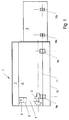
- Eine Brennkraftmaschine, bei der der Generator direkt angeflanscht ist,
- Figur 2:
- ein Ausführungsbeispiel, bei der der Generator über eine Zwischenglocke an der Brennkraftmaschine angeflanscht ist und
- Figur 3:
- einen teilweisen Querschnitt durch das Kurbelgehäuse und die Ölwanne der Brennkraftmaschine mit der erfindungsgemäß ausgebildeten Lagerung.
- Figure 1:
- An internal combustion engine in which the generator is flanged directly,
- Figure 2:
- an embodiment in which the generator is flanged to the internal combustion engine via an intermediate bell and
- Figure 3:
- a partial cross section through the crankcase and the oil pan of the internal combustion engine with the bearing designed according to the invention.
Die schematisch in Figur 1 dargestellte Brennkraftmaschine ist insbesondere eine selbstzündende Brennkraftmaschine in V-Bauart mit einer Zylinderleistung bis ca. 300 kW. Diese Brennkraftmaschine 1 weist ein Kurbelgehäuse 2 auf, in dem eine Kurbelwelle 3 drehbar gelagert ist. An diese Kurbelwelle 3 sind Pleuel 4 angelenkt, die jeweils einen Kolben 5 tragen. Die Kolben 5 gleiten in Zylindern 6, wobei die Zylinder von Zylinderköpfen 7 abgedeckt sind. An die Brennkraftmaschine 1 ist ein Aggregat, insbesondere ein Generator 8 angeflanscht. Dieser Generator 8 ist mit der Brennkraftmaschine im Bereich des Kurbelgehäuses 2 und der Ölwanne 12 verschraubt, wobei beide Bauelemente zusammen eine selbsttragende Einheit bilden. Gelagert ist die Einheit über Lager 9a, 9b, 9'a, 9'b, 10a, 10b, 10'a, 10'b. Dabei sind die Lager 9a, 9b, 9'a, 9'b an der Brennkraftmaschine 1 in Höhe der Trennfuge 11 zwischen Kurbelgehäuse 2 und Ölwanne 12 befestigt. Die Lager 9a, 9b, 9'a, 9'b weisen jeweils zwei Winkel 13a, 13b (Fig. 3) auf, die mit je einem Schenkel zusammenliegend die Auflage für ein Dämpfungs- und Tragelement 14 bilden. Die jeweils voneinander wegweisenden zweiten Schenkel der Winkel 13a, 13b sind mit dem Kurbelgehäuse 2 und der Ölwanne 12 verschraubt.The internal combustion engine shown schematically in FIG. 1 is, in particular, a self-igniting V-type internal combustion engine with a cylinder output of up to approximately 300 kW. This
Je nach Ausbildung und Größe der Brennkraftmaschine 1 und des angeflanschten Generators 8 ruht das Gewicht dieser Baueinheit nur auf den Lagern 9a, 9'a und 10b, 10'b. Die Lager 9b, 9'b und 10a, 10'a können in diesem Falle wegbleiben oder nur zu Montagezwecken von der Brennkraftmaschine 1 und dem Generator 8 benutzt werden um diese alleine auf dem Untergrund abstellen zu können.Depending on the design and size of the
Im wesentlichen Unterschied zu der Ausbildung gemäß Figur 1 ist in der Ausführungsform nach Figur 2 der Generator unter Zwischenfügung einer Zwischenglocke 15 an der Brennkraftmaschine 1 angeflanscht. Auch bei dieser Ausführungsform ist es wesentlich, daß die gesamte Baueinheit eine selbsttragende Einheit bildet. Dabei ist in der Zwischenglocke 15 die Kurbelwelle 3 beziehungsweise ein daran befestigter Abtriebsflansch mit der Genertorwelle 16 verbunden. Dabei kann je nach Erfordernissen hier auch ein koaxiales Getriebe zwischengeschaltet sein.In essence, in contrast to the design according to FIG. 1, in the embodiment according to FIG. 2 the generator is flanged to the
Claims (12)
dadurch gekennzeichnet, daß die Brennkraftmaschine (1) und das Aggregat eine selbsttragende Einheit bilden, und daß Lager (9a, 9'a, 10b 10'b) stirnseitig der Brennkraftmaschine (1) und endseitig dem Aggregat angeordnet sind.Internal combustion engine, in particular a self-igniting internal combustion engine, which has a crankcase in which a crankshaft is rotatably mounted, on which at least one connecting rod carrying a piston is articulated, the piston being movable in a cylinder covered by a cylinder head, and the crankcase on the crankshaft side by an oil pan is closed, the internal combustion engine being able to be set up on a base via bearings and an aggregate being drivable by the crankshaft,
characterized in that the internal combustion engine (1) and the unit form a self-supporting unit, and in that bearings (9a, 9'a, 10b 10'b) are arranged on the front side of the internal combustion engine (1) and on the end side of the unit.
dadurch gekennzeichnet, daß das Aggregat ein Generator (8) ist.Internal combustion engine according to claim 1,
characterized in that the unit is a generator (8).
dadurch gekennzeichnet, daß Lager (9b, 9'b, 10a 10'a) generatorseitig an der Brennkraftmaschine (1) und/oder brennkraftmaschinenseitig an dem Generator (8) angeordnet sind.Internal combustion engine according to claim 1 or 2,
characterized in that bearings (9b, 9'b, 10a 10'a) are arranged on the generator side on the internal combustion engine (1) and / or on the internal combustion engine side on the generator (8).
dadurch gekennzeichnet, daß die Lager (9b, 9'b, 10a 10'a) generatorseitig der Brennkraftmaschine (1) und/oder brennkraftmaschinenseitig an dem Generator (8) als Traglager ausgebildet sind.Internal combustion engine according to one of the preceding claims,
characterized in that the bearings (9b, 9'b, 10a 10'a) on the generator side of the internal combustion engine (1) and / or on the internal combustion engine side on the generator (8) are designed as support bearings.
dadurch gekennzeichnet, daß die Ölwanne (12) als tragendes Element ausgebildet ist.Internal combustion engine according to one of the preceding claims,
characterized in that the oil pan (12) is designed as a supporting element.
dadurch gekennzeichnet, daß Lager (9a, 9'a, 9b 9'b) an dem Kurbelgehäuse (2) und/oder der Ölwanne (12) befestigbar sind.Internal combustion engine according to one of the preceding claims,
characterized in that bearings (9a, 9'a, 9b 9'b) can be fastened to the crankcase (2) and / or the oil pan (12).
dadurch gekennzeichnet, daß je ein Lager (9a, 9'a, 9b 9'b) zwei Winkel (13a, 13b) aufweist, die mit je einem ersten Schenkel aneinanderliegend eine Anlage für ein Dämpfungs- und Tragelement bilden und der jeweils zweite Schenkel an dem Kurbelgehäuse (2) beziehungsweise der Ölwanne (12) befestigbar ist.Internal combustion engine according to one of the preceding claims,
characterized in that a respective bearing (9a, 9'a, 9b 9'b) has two angles (13a, 13b) which, with one first leg lying against the other, form a system for a damping and supporting element and the second leg the crankcase (2) or the oil pan (12) can be fastened.
dadurch gekennzeichnet, daß die aneinanderliegenden Schenkel angenähert in der Ebene der Trennfuge (11) zwischen Kurbelgehäuse (2) und Ölwanne (12) angeordnet sind.Internal combustion engine according to one of the preceding claims,
characterized in that the abutting legs are arranged approximately in the plane of the parting line (11) between the crankcase (2) and the oil pan (12).
dadurch gekennzeichnet, daß der Generator (8) direkt an der Brennkraftmaschine (1) oder über eine Zwischenglocke (15) an die Brennkraftmaschine (1) angekoppelt ist.Internal combustion engine according to one of the preceding claims,
characterized in that the generator (8) is coupled directly to the internal combustion engine (1) or via an intermediate bell (15) to the internal combustion engine (1).
dadurch gekennzeichnet, daß zwischen Kurbelwelle (3) und Welle (16) ein koaxiales Getriebe eingeschaltet ist.Internal combustion engine according to one of the preceding claims,
characterized in that a coaxial gear is engaged between the crankshaft (3) and the shaft (16).
dadurch gekennzeichnet, daß der Generator (8) und/oder die Zwischenglocke (15) mit dem Kurbelgehäuse (2) und der Ölwanne (12) verschraubt ist.Internal combustion engine according to one of the preceding claims,
characterized in that the generator (8) and / or the intermediate bell (15) is screwed to the crankcase (2) and the oil pan (12).
dadurch gekennzeichnet, daß die Kurbelwelle (3) mit der Welle (16) des Generators (8) sowohl radial als auch axial starr und in Drehrichtung elastisch oder starr gekoppelt ist.Internal combustion engine according to one of the preceding claims,
characterized in that the crankshaft (3) is rigidly coupled to the shaft (16) of the generator (8) both radially and axially and elastically or rigidly in the direction of rotation.
Applications Claiming Priority (2)
| Application Number | Priority Date | Filing Date | Title |
|---|---|---|---|
| DE19535942A DE19535942B4 (en) | 1995-09-27 | 1995-09-27 | Bearing arrangement for a drive train |
| DE19535942 | 1995-09-27 |
Publications (3)
| Publication Number | Publication Date |
|---|---|
| EP0789139A2 true EP0789139A2 (en) | 1997-08-13 |
| EP0789139A3 EP0789139A3 (en) | 1998-07-22 |
| EP0789139B1 EP0789139B1 (en) | 2001-03-14 |
Family
ID=7773327
Family Applications (1)
| Application Number | Title | Priority Date | Filing Date |
|---|---|---|---|
| EP96115093A Revoked EP0789139B1 (en) | 1995-09-27 | 1996-09-20 | Combustion engine with flanged generator |
Country Status (3)
| Country | Link |
|---|---|
| EP (1) | EP0789139B1 (en) |
| AT (1) | ATE199686T1 (en) |
| DE (2) | DE19535942B4 (en) |
Cited By (2)
| Publication number | Priority date | Publication date | Assignee | Title |
|---|---|---|---|---|
| EP0952334A2 (en) | 1998-04-23 | 1999-10-27 | Design & Manufacturing Solutions, Inc. | Pneumatically controlled compressed air assisted fuel injection system |
| CN102678813A (en) * | 2012-05-24 | 2012-09-19 | 中联重科股份有限公司 | Buffer unit and boom rearward tilting prevention device provided with buffer unit |
Families Citing this family (3)
| Publication number | Priority date | Publication date | Assignee | Title |
|---|---|---|---|---|
| JP3423864B2 (en) * | 1997-09-12 | 2003-07-07 | 本田技研工業株式会社 | Hybrid vehicle drive |
| DE102006037963A1 (en) * | 2006-08-12 | 2008-02-14 | Deutz Ag | IC Engine-machine unit is mounted on common support, air intake for engine running transversely through support and connecting with filter unit integrated with it and connected to engine by separate pipe |
| DE102011102774A1 (en) * | 2011-05-28 | 2012-11-29 | Volkswagen Aktiengesellschaft | Range extender for vehicle, comprises internal combustion engine, where internal combustion engine is driven by generator, which generates electric current and distance of bearing of crankshaft axis is in range of twenty to fifty centimeter |
Citations (8)
| Publication number | Priority date | Publication date | Assignee | Title |
|---|---|---|---|---|
| DE2302995A1 (en) † | 1972-02-04 | 1973-08-16 | Berliet Automobiles | HOUSING FOR COMBUSTION MACHINERY OF VEHICLES |
| DE7932802U1 (en) * | 1979-11-20 | 1980-05-08 | Elin-Union Ag Fuer Elektrische Industrie, Wien | Self-sufficient, mobile energy center |
| DE3035943A1 (en) * | 1980-09-24 | 1982-05-06 | Volkswagenwerk Ag, 3180 Wolfsburg | Vibration insulated vehicle power unit - has engine block connected to gearbox by flexible plates which permit some torsional movement |
| DE8334714U1 (en) * | 1983-12-03 | 1984-05-03 | Wirges, Gerhard, 2000 Hamburg | POWER GENERATOR |
| DE3334429A1 (en) * | 1983-09-23 | 1985-04-11 | Lindenberg Aggregate GmbH, 5064 Rösrath | Combustion engine with generator for electrical current generation |
| DE3809568A1 (en) * | 1988-03-22 | 1989-10-12 | Kloeckner Humboldt Deutz Ag | Mounting for an internal combustion engine with auxiliary unit |
| EP0348253A1 (en) * | 1988-06-22 | 1989-12-27 | Automobiles Peugeot | Front structure of a motor vehicle with transversallly mounted engine |
| DE4433281A1 (en) * | 1994-09-19 | 1996-03-28 | Motoren Werke Mannheim Ag | Automotive IC engine support bearing |
Family Cites Families (3)
| Publication number | Priority date | Publication date | Assignee | Title |
|---|---|---|---|---|
| DE1750077U (en) * | 1956-06-06 | 1957-08-08 | Siemens Ag | Electrical machine that is driven by a prime mover, especially with pulsating torque. |
| DE3536247A1 (en) * | 1985-10-10 | 1987-04-16 | Jenbacher Werke Vertriebsgesel | Vehicle, especially commercial vehicle with hybrid drive |
| DE4404791C1 (en) * | 1994-02-08 | 1995-03-30 | Mannesmann Ag | Structural unit comprising an internal combustion engine and an electrical generator |
-
1995
- 1995-09-27 DE DE19535942A patent/DE19535942B4/en not_active Revoked
-
1996
- 1996-09-20 AT AT96115093T patent/ATE199686T1/en not_active IP Right Cessation
- 1996-09-20 EP EP96115093A patent/EP0789139B1/en not_active Revoked
- 1996-09-20 DE DE59606590T patent/DE59606590D1/en not_active Revoked
Patent Citations (8)
| Publication number | Priority date | Publication date | Assignee | Title |
|---|---|---|---|---|
| DE2302995A1 (en) † | 1972-02-04 | 1973-08-16 | Berliet Automobiles | HOUSING FOR COMBUSTION MACHINERY OF VEHICLES |
| DE7932802U1 (en) * | 1979-11-20 | 1980-05-08 | Elin-Union Ag Fuer Elektrische Industrie, Wien | Self-sufficient, mobile energy center |
| DE3035943A1 (en) * | 1980-09-24 | 1982-05-06 | Volkswagenwerk Ag, 3180 Wolfsburg | Vibration insulated vehicle power unit - has engine block connected to gearbox by flexible plates which permit some torsional movement |
| DE3334429A1 (en) * | 1983-09-23 | 1985-04-11 | Lindenberg Aggregate GmbH, 5064 Rösrath | Combustion engine with generator for electrical current generation |
| DE8334714U1 (en) * | 1983-12-03 | 1984-05-03 | Wirges, Gerhard, 2000 Hamburg | POWER GENERATOR |
| DE3809568A1 (en) * | 1988-03-22 | 1989-10-12 | Kloeckner Humboldt Deutz Ag | Mounting for an internal combustion engine with auxiliary unit |
| EP0348253A1 (en) * | 1988-06-22 | 1989-12-27 | Automobiles Peugeot | Front structure of a motor vehicle with transversallly mounted engine |
| DE4433281A1 (en) * | 1994-09-19 | 1996-03-28 | Motoren Werke Mannheim Ag | Automotive IC engine support bearing |
Non-Patent Citations (1)
| Title |
|---|
| PA 665981 - 15.12.51 † |
Cited By (3)
| Publication number | Priority date | Publication date | Assignee | Title |
|---|---|---|---|---|
| EP0952334A2 (en) | 1998-04-23 | 1999-10-27 | Design & Manufacturing Solutions, Inc. | Pneumatically controlled compressed air assisted fuel injection system |
| CN102678813A (en) * | 2012-05-24 | 2012-09-19 | 中联重科股份有限公司 | Buffer unit and boom rearward tilting prevention device provided with buffer unit |
| CN102678813B (en) * | 2012-05-24 | 2013-06-26 | 中联重科股份有限公司 | Buffer unit and boom rearward tilting prevention device provided with buffer unit |
Also Published As
| Publication number | Publication date |
|---|---|
| DE59606590D1 (en) | 2001-04-19 |
| DE19535942A1 (en) | 1997-04-03 |
| ATE199686T1 (en) | 2001-03-15 |
| EP0789139A3 (en) | 1998-07-22 |
| EP0789139B1 (en) | 2001-03-14 |
| DE19535942B4 (en) | 2004-07-01 |
Similar Documents
| Publication | Publication Date | Title |
|---|---|---|
| DE4019304C1 (en) | ||
| EP0599125B1 (en) | Driving arrangement for the balancing shaft of a V-type engine | |
| DE69635136T2 (en) | DEVICE FOR DIRECTLY CONNECTING A COMBUSTION ENGINE TO A GEARED MACHINE | |
| DD256894A5 (en) | PISTON COMBUSTION ENGINES | |
| DE102006009152A1 (en) | Built up crankshaft for four stroke diesel internal combustion engine has friction or form locked components with defined relative dimensions | |
| DE3120190A1 (en) | Internal combustion engine with reciprocating pistons and a crankshaft | |
| EP0944784B1 (en) | Supporting structure for the crankcase of a reciprocating piston internal combustion engine | |
| EP1222411A1 (en) | Compensating shaft assembly for piston engines | |
| EP0789139A2 (en) | Combustion engine with flanged generator | |
| DE19535963B4 (en) | System for taking power from a crankshaft | |
| DE3119362C2 (en) | Four-cylinder internal combustion engine with a second-order mass balance | |
| DE102007043610A1 (en) | Combustion engine for a motor vehicle comprises an unbalanced weight arranged on a unit which is connected to a crankshaft | |
| WO1981002040A1 (en) | Piston machine | |
| DE3225975C1 (en) | Compound crankshaft | |
| DE2126059A1 (en) | Crankshaft with connecting rod bearings for reciprocating engines | |
| WO2010121710A1 (en) | Internal combustion engine | |
| DE2044943A1 (en) | Reciprocating machine based on the modular principle | |
| EP0584427B1 (en) | Two cycle internal combustion engine | |
| DE10042212C2 (en) | Low-vibration piston compressor for vehicles | |
| DE102009050628B4 (en) | Device for compensating for the second-order inertial forces for an in-line piston internal combustion engine | |
| WO2002044564A1 (en) | Low-vibration multi-stage piston compressor | |
| DE3903419A1 (en) | Mass-balancing arrangement | |
| WO2002018788A1 (en) | Piston compressor having a dynamic mass compensation in the region of the crank mechanism | |
| DE20080161U1 (en) | Crankshaft for a high-speed in-line four-cylinder piston engine, especially an internal combustion engine | |
| DE102022106397A1 (en) | inertial force balancing system |
Legal Events
| Date | Code | Title | Description |
|---|---|---|---|
| PUAI | Public reference made under article 153(3) epc to a published international application that has entered the european phase |
Free format text: ORIGINAL CODE: 0009012 |
|
| AK | Designated contracting states |
Kind code of ref document: A2 Designated state(s): AT DE FI FR GB IT NL |
|
| PUAL | Search report despatched |
Free format text: ORIGINAL CODE: 0009013 |
|
| RHK1 | Main classification (correction) |
Ipc: B60K 5/12 |
|
| AK | Designated contracting states |
Kind code of ref document: A3 Designated state(s): AT DE FI FR GB IT NL |
|
| 17P | Request for examination filed |
Effective date: 19990118 |
|
| 17Q | First examination report despatched |
Effective date: 19991115 |
|
| RAP1 | Party data changed (applicant data changed or rights of an application transferred) |
Owner name: DEUTZ AKTIENGESELLSCHAFT |
|
| GRAG | Despatch of communication of intention to grant |
Free format text: ORIGINAL CODE: EPIDOS AGRA |
|
| GRAG | Despatch of communication of intention to grant |
Free format text: ORIGINAL CODE: EPIDOS AGRA |
|
| GRAH | Despatch of communication of intention to grant a patent |
Free format text: ORIGINAL CODE: EPIDOS IGRA |
|
| GRAH | Despatch of communication of intention to grant a patent |
Free format text: ORIGINAL CODE: EPIDOS IGRA |
|
| GRAA | (expected) grant |
Free format text: ORIGINAL CODE: 0009210 |
|
| AK | Designated contracting states |
Kind code of ref document: B1 Designated state(s): AT DE FI FR GB IT NL |
|
| PG25 | Lapsed in a contracting state [announced via postgrant information from national office to epo] |
Ref country code: NL Free format text: LAPSE BECAUSE OF FAILURE TO SUBMIT A TRANSLATION OF THE DESCRIPTION OR TO PAY THE FEE WITHIN THE PRESCRIBED TIME-LIMIT Effective date: 20010314 Ref country code: IT Free format text: LAPSE BECAUSE OF FAILURE TO SUBMIT A TRANSLATION OF THE DESCRIPTION OR TO PAY THE FEE WITHIN THE PRE;WARNING: LAPSES OF ITALIAN PATENTS WITH EFFECTIVE DATE BEFORE 2007 MAY HAVE OCCURRED AT ANY TIME BEFORE 2007. THE CORRECT EFFECTIVE DATE MAY BE DIFFERENT FROM THE ONE RECORDED.SCRIBED TIME-LIMIT Effective date: 20010314 Ref country code: GB Free format text: LAPSE BECAUSE OF FAILURE TO SUBMIT A TRANSLATION OF THE DESCRIPTION OR TO PAY THE FEE WITHIN THE PRESCRIBED TIME-LIMIT Effective date: 20010314 Ref country code: FR Free format text: LAPSE BECAUSE OF FAILURE TO SUBMIT A TRANSLATION OF THE DESCRIPTION OR TO PAY THE FEE WITHIN THE PRESCRIBED TIME-LIMIT Effective date: 20010314 Ref country code: FI Free format text: LAPSE BECAUSE OF FAILURE TO SUBMIT A TRANSLATION OF THE DESCRIPTION OR TO PAY THE FEE WITHIN THE PRESCRIBED TIME-LIMIT Effective date: 20010314 |
|
| REF | Corresponds to: |
Ref document number: 199686 Country of ref document: AT Date of ref document: 20010315 Kind code of ref document: T |
|
| REF | Corresponds to: |
Ref document number: 59606590 Country of ref document: DE Date of ref document: 20010419 |
|
| NLV1 | Nl: lapsed or annulled due to failure to fulfill the requirements of art. 29p and 29m of the patents act | ||
| EN | Fr: translation not filed | ||
| GBV | Gb: ep patent (uk) treated as always having been void in accordance with gb section 77(7)/1977 [no translation filed] |
Effective date: 20010314 |
|
| PG25 | Lapsed in a contracting state [announced via postgrant information from national office to epo] |
Ref country code: AT Free format text: LAPSE BECAUSE OF NON-PAYMENT OF DUE FEES Effective date: 20010920 |
|
| PLBQ | Unpublished change to opponent data |
Free format text: ORIGINAL CODE: EPIDOS OPPO |
|
| PLBI | Opposition filed |
Free format text: ORIGINAL CODE: 0009260 |
|
| 26 | Opposition filed |
Opponent name: MTU FRIEDRICHSHAFEN GMBH PATENTABTEILUNG ZJXP Effective date: 20011214 |
|
| PLBF | Reply of patent proprietor to notice(s) of opposition |
Free format text: ORIGINAL CODE: EPIDOS OBSO |
|
| PLBF | Reply of patent proprietor to notice(s) of opposition |
Free format text: ORIGINAL CODE: EPIDOS OBSO |
|
| PLBF | Reply of patent proprietor to notice(s) of opposition |
Free format text: ORIGINAL CODE: EPIDOS OBSO |
|
| PLAW | Interlocutory decision in opposition |
Free format text: ORIGINAL CODE: EPIDOS IDOP |
|
| PGFP | Annual fee paid to national office [announced via postgrant information from national office to epo] |
Ref country code: DE Payment date: 20030925 Year of fee payment: 8 |
|
| RDAF | Communication despatched that patent is revoked |
Free format text: ORIGINAL CODE: EPIDOSNREV1 |
|
| RDAG | Patent revoked |
Free format text: ORIGINAL CODE: 0009271 |
|
| STAA | Information on the status of an ep patent application or granted ep patent |
Free format text: STATUS: PATENT REVOKED |
|
| 27W | Patent revoked |
Effective date: 20040823 |