EP0788254A2 - Data structure, data communication method, apparatus and communication terminal apparatus - Google Patents
Data structure, data communication method, apparatus and communication terminal apparatus Download PDFInfo
- Publication number
- EP0788254A2 EP0788254A2 EP97300550A EP97300550A EP0788254A2 EP 0788254 A2 EP0788254 A2 EP 0788254A2 EP 97300550 A EP97300550 A EP 97300550A EP 97300550 A EP97300550 A EP 97300550A EP 0788254 A2 EP0788254 A2 EP 0788254A2
- Authority
- EP
- European Patent Office
- Prior art keywords
- frame
- data
- feedback frame
- transmission
- bit stream
- Prior art date
- Legal status (The legal status is an assumption and is not a legal conclusion. Google has not performed a legal analysis and makes no representation as to the accuracy of the status listed.)
- Granted
Links
Images


Classifications
-
- H—ELECTRICITY
- H04—ELECTRIC COMMUNICATION TECHNIQUE
- H04L—TRANSMISSION OF DIGITAL INFORMATION, e.g. TELEGRAPHIC COMMUNICATION
- H04L1/00—Arrangements for detecting or preventing errors in the information received
- H04L1/12—Arrangements for detecting or preventing errors in the information received by using return channel
- H04L1/16—Arrangements for detecting or preventing errors in the information received by using return channel in which the return channel carries supervisory signals, e.g. repetition request signals
- H04L1/18—Automatic repetition systems, e.g. Van Duuren systems
- H04L1/1809—Selective-repeat protocols
-
- H—ELECTRICITY
- H04—ELECTRIC COMMUNICATION TECHNIQUE
- H04L—TRANSMISSION OF DIGITAL INFORMATION, e.g. TELEGRAPHIC COMMUNICATION
- H04L1/00—Arrangements for detecting or preventing errors in the information received
- H04L1/12—Arrangements for detecting or preventing errors in the information received by using return channel
- H04L1/16—Arrangements for detecting or preventing errors in the information received by using return channel in which the return channel carries supervisory signals, e.g. repetition request signals
- H04L1/1607—Details of the supervisory signal
- H04L1/1664—Details of the supervisory signal the supervisory signal being transmitted together with payload signals; piggybacking
-
- H—ELECTRICITY
- H04—ELECTRIC COMMUNICATION TECHNIQUE
- H04L—TRANSMISSION OF DIGITAL INFORMATION, e.g. TELEGRAPHIC COMMUNICATION
- H04L1/00—Arrangements for detecting or preventing errors in the information received
- H04L1/12—Arrangements for detecting or preventing errors in the information received by using return channel
- H04L2001/125—Arrangements for preventing errors in the return channel
Definitions
- FIGURE 10 is a schematic block diagram showing an arrangement of a communication terminal apparatus such as a portable telephone or the like to which the present invention is applied.
- a speech of a user is picked up by a microphone 10A.
- the picked-up speech is supplied to a speech signal processing unit 10B in which it is converted into a speech signal.
- the speech signal is supplied through a baseband digital signal processing circuit 10C, a TDMA/TDD processing circuit 10D, a modulation unit 10E, and an RF unit sequentially to an antenna 10H.
- a transmission frame converted from the speech signal is transmitted from the antenna 10H.
- the error detecting code E employs the ITU - T (16 bits) of the CRC code, for example.
- a region in which the CRC is applied is a region of 624 bits from the transmission data length A to the repeat request frame number D.
- the data row (bit strings) constituting the feedback frame or the data frame are supplied to the input terminal 6, thereby being arrayed consecutively from the D640 (MSB) to D1 (LSB).
- the data row is supplied to the FF circuit R0, or a first stage of the shift register which is formed of 16 D-type flip-flop circuits (hereinafter simply referred to as FF circuit) R0, R1, ..., R14, R15 connected in a cascade fashion.
- the data is shifted in the left-hand direction in the figure.
- the feedback frame arranged as described above is transmitted from the reception side to the transmission side. Therefore, if the data length of the transmission data to be transported by the feedback frame on the reception side is shorter than the predetermined data length which derives from the format of the frame, the feedback frame can be transmitted from the reception side to the transmission side without changing the format of the feedback frame and lowering the reception rate.
Abstract
Description
- The present invention relates to a data communication method (wireless digital communication method) in which error control is carried out based on an automatic repeat request system.
- As an error control method in data communication, there has been proposed an error control method in an automatic repeat request (ARQ: Automatic Repeat Request or Automatic Request for Repetition) system. According to the error control method based on the automatic repeat request system, if a data frame transmitted from a transmission side to a reception side contains an error, the data frame is again transmitted from the transmission side to the reception side on the basis of the repeat request issued from the reception side to the transmission side.
- Various methods have been proposed as the error control method of the automatic repeat request system. Now, a prior art example of an automatic repeat request error control method of a selective repeat (hereinafter referred to as SR) system will hereinafter be described. The selective repeat request system theoretically requires a buffer memory having an unlimited capacity. Thus, such system is not employed normally, but its improved type is utilized. An automatic repeat request error control method of a primitive SR system will hereinafter be described for making explanation easy.
- Initially, an example of an arrangement of an ARQ frame in which a data frame and a feedback frame have an identical format will be described with reference to FIGURE 1 of the accompanying drawings. The ARQ frame includes each data of a transmission data frame length A of 16 bits, for example, a transmission data B of 584 bits, for example, a transmission data frame number C of 8 bits, for example, and a repeat request frame number D of 8 bits, for example, and the frame is further added with an error detecting code E of 16 bits, for example. This error detecting code E serves for detecting an error which can be contained in the entirety of the data.
- The transmission data length A can take a value of the data amount of the transmission data B, e.g., values from 0 to 584 in a bit unit. In this case, the data amount thereof is 584 bits. The transmission frame number C indicates a frame number of a frame to be transmitted, and hence the number can take a number from 1 to 255. The repeat request frame number D is utilized in a feedback frame to be transmitted from the reception side to the transmission side, and it indicates a frame number of a frame that is expected to be received next on the reception side, i.e., the earliest frame number that has not been received yet.
- The error detecting code E is arranged as a CRC (Cyclic Redundancy check) based on an advice of an ITU (International Telecommunication(s) Union) - T (16 bits). The CRC is effective for detecting an error contained in a region of 624 bits, i.e., the region from the transmission data length A to the repeat request frame number D.
- Now, a manner for transmitting an ARQ frame based on the SR system when the transmission frame can be transmitted with failure will be described with reference to FIGURE 2 below. As shown in FIGURE 2, rectangular frames, each having a numeral written therein, arrayed on the transmission side depict transmission frames, and each numeral written therein designates a frame number. Rectangular frames arrayed on the reception side depict repeat request frames, and each numeral written in each of them also designates a frame number. Although a data frame is originally transmitted from the transmission side to the reception side, there is no data frame originally transmitted from the reception side to the transmission side.
- Operations carried out on the transmission side are as follow:
- (1) A transmitter on the transmission side transmits
transmission frames - (2) A feedback frame of a repeat request frame number, 2 is received from the reception side. Thus, it is determined that the
transmission frame 1 is correctly received on the reception side. Atransmission frame 4 is transmitted next. - (3) A feedback frame of a repeat request frame number, 3 is received. Thus, it is determined that the
transmission frame 2 is correctly received on the reception side. Atransmission frame 5 is transmitted next. - (4) A feedback frame of the repeat request frame number, 3 again is received. Thus, it is determined that the
transmission frame 3 does not correctly reach the reception side. Therefore, thetransmission frame 3 is again transmitted. - (5) A feedback frame of the repeat request frame number, 3 is again received. Thus, it is also determined that the
transmission frame 3 does not correctly reach the reception side. However, since thetransmission frame 3 has been already retransmitted, atransmission frame 6 is transmitted next. - (6) A feedback frame of the repeat request frame number, 3 is again received. Thus, it is determined that the
transmission frame 3 does not correctly reach the reception side. However, since thetransmission frame 3 has been already retransmitted, atransmission frame 7 is transmitted next. - (7) A feedback frame of a repeat request frame number, 6 is received. Thus, it is determined that the
transmission frames - Operations carried out on the reception side are as follow:
- (1) When a receiver on the reception side receives the
transmission frame 1 correctly, the feedback frame of the repeat request frame number, 2 is transmitted as a repeat request frame.
When the receiver receives thetransmission frame 2 correctly, the feedback frame of the repeat request frame number, 3 is transmitted as a repeat request frame. - (2) The
transmission frame 3 is received incorrectly. The repeat request frame number, 3 is transmitted with the feedback frame. - (3) The
transmission frames transmission frame 3 has not been reached, the feedback frame of the repeat request frame number, 3 is transmitted. - (4) The
transmission frame 3, which is again transmitted as the retransmitted frame, is correctly received. Since thetransmission frame 5 has been correctly received so far, a feedback frame with the repeat request frame number, 6 is transmitted as a frame that is expected to be received next on the reception side. - As described above, according to the error control method of the automatic repeat request system based on the SR system, the transmitter on the transmission side is transmitting data frames continuously until it receives the feedback frame indicating that a frame reaches the reception side incorrectly. If the transmitter receives information indicative of that the frame has reached incorrectly, then it transmits the data frame again. In this manner, the communication system is controlled to recover erroneous data transmission from the transmission side to the reception side.
- While in the above case described with reference to FIGURE 2, it is assumed that the feedback frame can be transmitted from the reception side to the transmission side without failure, the feedback frame naturally can be transmitted with failure in the actual transmission path, i.e., a space through which electric wave propagates. Now, a manner of the ARQ transmission based on the SR system when the feedback frame is failed to be transmitted will be described with reference to FIGURE 3.
- Operations carried out on the transmission side are as follow:
- (1) The
transmission frames - (2) The feedback frame of a repeat request frame number, 2 is received from the reception side. Thus, it is determined that the
transmission frame 1 correctly reaches the reception side, and thetransmission frame 4 is transmitted. - (3) The feedback frame of the repeat request frame number, 3 is received. Thus, it is determined that the
transmission frame 2 correctly reaches the reception side, and thetransmission frame 5 is transmitted. - (4) A feedback frame of the repeat request number, 4 is not received. Thus, it is presumed that the
transmission frame 3 did not correctly reach, and hence thetransmission frame 3 is again transmitted. - (5) A feedback frame of the repeat request frame number, 5 is received. Thus, it is determined that the
transmission frames transmission frame 6 is transmitted. - (6) A feedback frame of the repeat request frame number, 6 is received. Thus, it is determined that the
transmission frame 5 has correctly reached the reception side, and thetransmission frame 7 is transmitted next. - Operations carried out on the reception side are as follow:
- (1) The transmission frames 1, 2, 3, 4 and 5 are correctly received. The feedback frames of repeat request frame numbers, 2, 3, 4, 5 and 6 are respectively transmitted.
- (2) The
transmission frame 3 is again correctly received. Since thetransmission frame 3 has been already received, the receivedtransmission frame 3 received in an overlapping fashion is discarded. The feedback frame of the repeat request frame number, 6 is transmitted. - As described above, according to the SR system of the prior art example, when the feedback frame is failed to be transmitted, leading to presumption that the corresponding transmission frame is incorrectly received on the transmission side, the data frame is transmitted in an overlapping fashion from the transmission side to the reception side in spite of the fact that the data frame has been correctly transmitted from the transmission side to the reception side.
- In this case, the ARQ frame is arranged based on a full duplex communication system as described above. Therefore, the system is requested to permit data transmission not only from the transmission side to the reception side but also from the reception side to the transmission side at a time. Accordingly, the data frame transmitted from the transmission side to the reception side and the feedback frame transmitted from the reception side to the transmission side have a common format. Therefore, even if there is no transmission data to be transmitted from the reception side with the feedback frame, upon transmission from the reception side to the transmission side, extra information (redundant portion of data) such as "transmission data length", "transmission data", "transmission frame number" and so on have to be included in the feedback frame for maintaining the frame arrangement described with reference to FIGURE 1. Which fact leads to a drawback that the reception rate at the transmission side is lowered, resulting in lowering of throughput.
- In general, a communication protocol is designed to permit the full duplex communication to be executable. However, in an actual practice, communication is often accomplished in a half duplex fashion, i.e., data delivery confirmation is effected in a step-by-step fashion, and hence it is not always necessary to transport data by the feedback frame from the reception side at a time. Therefore, it is undesirable to lower the throughput in spite of the fact that the feedback frame is not always requested to transport transmission data.
- Further, in a data communication method in which the data frame transmitted from the transmission side to the reception side and the feedback frame transmitted from the reception side to the transmission side have an identical format, when transmission data to be transported by the data frame or the feedback frame is greatly shorter (LBx is taken as its data length) than a predetermined data length (LB0 is taken as the length which derives from the format), also reception rate is lowered upon transmission with the predetermined data length LB0 maintained as it is.
- Therefore, it is a general object of the present invention to provide an improved communication method and communication apparatus in which the aforesaid shortcomings and disadvantages encountered with the prior art can be eliminated.
- More specifically, it is an object of the present invention to propose a communication method utilized for communication in which the data frame transmitted from the transmission side to the reception side and the feedback frame transmitted from the reception side to the transmission side have an identical format, wherein even if there is no substantial transmission data to be transported by the feedback frame from the reception side, the feedback frame can be transmitted from the reception side to the transmission side without changing the format of the feedback frame and lowering the reception rate.
- It is another object of the present invention to propose a communication method utilized for communication in which the data frame transmitted from the transmission side to the reception side and the feedback frame transmitted from the reception side to the transmission side have an identical format, wherein if the data length of the transmission data to be transported by the feedback frame on the reception side or the transmission data to be transported by the data frame on the transmission side, is shorter than the predetermined data length, then the feedback frame or the data frame is arranged to be transmitted from the reception side to the transmission side or from the transmission side to the reception side without changing the format of the feedback frame or the data frame and lowering the reception rate.
- According to one aspect of the present invention, there is provided a data structure utilized for communication in which a data frame transmitted from a transmitter and a feedback frame fed back from a receiver have an identical format, wherein a redundant portion of the feedback frame is substituted with a predetermined bit stream.
- According to a second aspect of the present invention, there is provided a communication method utilized for communication in which a data frame transmitted from a transmitter and a feedback frame fed back from a receiver have an identical format, comprising a step of substituting a redundant portion of the feedback frame with a predetermined bit stream upon forming the feedback frame containing substantial information.
- According to a third aspect of the present invention, there is provided a communication method utilized for communication in which a data frame transmitted from a transmitter and a feedback frame fed back from a receiver have an identical format and also utilized by the transmitter which receives the feedback frame from the receiver, comprising steps of determining whether or not a redundant portion of the feedback frame transmitted from the receiver consists of a first predetermined bit stream, and substituting another redundant portion of the feedback frame other than that redundant portion with a second predetermined bit stream if it is determined that that redundant portion of the feedback frame consists of the first predetermined bit stream.
- According to a fourth aspect of the present invention, there is provided a communication apparatus utilized for communication in which a data frame transmitted from a transmitter and a feedback frame fed back from a receiver have an identical format, comprising a feedback frame input terminal means for being supplied with the feedback frame, a determining means for determining whether or not a redundant portion of the feedback frame consists of a first predetermined bit stream, a second predetermined bit stream generating means for generating a second predetermined bit stream, substituting means for substituting another redundant portion of the feedback frame other than that redundant portion with a second predetermined bit stream if it is determined that that redundant portion of the feedback frame consists of the first predetermined bit stream, and an error detecting means for detecting an error in an output signal supplied from said substituting means.
- According to a fifth aspect of the present invention, there is provided a communication apparatus utilized for communication in which a data frame transmitted from a transmitter and a feedback frame fed back from a receiver have an identical format, comprising an antenna for transmitting and receiving a radio wave, a received signal processing means for processing a received signal, a transmitting signal processing means for processing a transmitting signal, and a baseband signal processing means for processing a baseband signal, wherein said baseband signal processing means is arranged to have a feedback frame input terminal means for being supplied with the feedback frame, a determining means for determining whether or not a redundant portion of the feedback frame consists of a first predetermined bit stream, a second predetermined bit stream generating means for generating a second predetermined bit stream, a substituting means for substituting another redundant portion of the feedback frame other than that redundant portion with a second predetermined bit stream if it is determined that that redundant portion of the feedback frame consists of the first predetermined bit stream, and an error detecting means for detecting an error in a signal supplied from the substituting means.
- The above and other objects, features, and advantages of the present invention will become apparent from the following detailed description of an illustrative embodiment thereof to be read in conjunction with the accompanying drawings, in which like reference numerals are used to identify the same or similar parts in the several views.
- The invention will be further described by way of non-limitative example with reference to the accompanying drawings, in which:-
- FIGURE 1 is a schematic diagram showing an example of an arrangement of an ARQ frame;
- FIGURE 2 is a diagram showing a manner of transmitting ARQ frames based on an SR system when a transmission frame is erroneously transmitted;
- FIGURE 3 is a diagram showing a manner of transmitting ARQ frames based on an SR system when the feedback frame is erroneously transmitted;
- FIGURE 4 is a schematic diagram showing an example of an arrangement of a feedback frame according to the present invention;
- FIGURE 5 is a flowchart showing a process for forming a feedback frame;
- FIGURE 6 is a flowchart showing a process for receiving and processing the feedback frame;
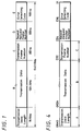
- FIGURE 7 is a schematic block diagram showing an example of an error detecting apparatus for detecting an error in the feedback frame according to the present invention;
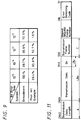
- FIGURES. 8A and 8B are diagrams useful for comparison between the present invention and the prior art example in length of an effective portion of the feedback frame;
- FIGURE 9 is a table useful for comparison between the present invention and the prior art example in a reception rate of a feedback frame when the feedback frame transports no substantial transmission data;
- FIGURE 10 is a schematic block diagram showing an arrangement of a communication terminal apparatus to which the present invention is applied;
- FIGURE 11 is a schematic diagram showing an example of an arrangement of a feedback frame according to the present invention, wherein the feedback frame contains substantial transmission data; and
- FIGURE 12 is a schematic block diagram showing an error detecting apparatus for detecting an error in the feedback frame or the data frame according to the present invention.
- An embodiment of the present invention will hereinafter be described with reference to the accompanied drawings. An ARQ data frame transmitted from the transmission side to the reception side and an ARQ feedback frame transmitted from the reception side to the transmission side have an identical format. As has been described with reference to FIGURE 1, the format includes a transmission data frame length A of 16 bits, for example, transmission data B of 584 bits, for example, a transmission data frame number C of 8 bits, for example, and a repeat request frame number D of 8 bits, for example, and the format is further added with an error detecting code E of 16 bits, for example, serving for the entirety of data.
- The transmission data length A can take a value of the data amount of the transmission data B, e.g., values from 0 to 584 in a bit unit. In this case, the data amount thereof is 584 bits. The transmission frame number C indicates a frame number of a frame to be transmitted (e.g., from 0 or 1 to 255). The repeat request frame number D is used in a feedback frame transmitted from the reception side to the transmission side, and it indicates a frame number of a frame that is expected to be received on the reception side (the oldest frame number that has not been received yet).
- The error detecting code E is arranged as a CRC (Cyclic Redundancy Check) code based on the ITU (International Telecommunication(s) Union) - T (16 bits) as described above. A region in which the CRC is applied is a region of 624 bits from the transmission data length A to the repeat request frame number D.
- Next, the format of the feedback frame to be transmitted from the reception side to the transmission side will be described with reference to FIGURE 4. The format of the feedback frame differs in values of the transmission data length A, transmission data B and transmission frame number C, depending on whether or not there is transmission data to be transmitted with the feedback frame. FIGURE 5 is a flowchart showing a process for forming a feedback frame. If there is transmission data to be transmitted with the feedback frame on the reception side, the feedback frame thereof takes the values described with reference to FIGURE 1, and is directly transmitted from the reception side to the transmission side.
- If there is no transmission data to be transmitted with the feedback frame on the reception side, the data of the transmission data length A of 16 bits, the transmission data B of 584 bits and the transmission frame number C of 8 bits are data unrelated to feedback information (a redundant portion of data). Therefore, they are all substituted with all zeros. The repeat request frame number D is kept as it is. Thus, the feedback frame is composed of the data of the transmission data length A of 16 bits, the transmission data B of 584 bits and the transmission frame number C of 8 bits, which are substituted with all zeros, the repeat request frame number D, and the error detecting code E of 16 bits serving for the entirety of data of 624 bits. The feedback frame is transmitted from the reception side to the transmission side.
- FIGURE 6 is a flowchart showing a process for receiving and processing the feedback frame. An error detecting apparatus, which is illustrated in FIGURE 7, is operated in accordance with the process of the flowchart in FIGURE 6, thereby detecting an error in the feedback frame received on the transmission side. Now, the operation of the error detecting apparatus will be described with reference to FIGURE 7. In FIGURE 7,
reference numeral 1 represents an all zero checking circuit, 3 an error detecting circuit, 8 a zero generator, 7 a changeover switch for carrying out switching action across aninput terminal 6 and the zerogenerator 8 so that theerror detecting circuit 3 is supplied with a data row from the input terminal and a data row of all zeros from the zero generators. Thechangeover switch 7 is controlled by a control signal supplied from the all zerochecking circuit 1 to acontrol terminal 2. - Data rows (bit strings) from D640 (MSB) to D1 (LSB) constituting the feedback frame are supplied to the
input terminal 6 sequentially, and the data rows are supplied to an FF circuit R0 at a first stage of a shift register which is composed of sixteen D-type flip-flop circuits (hereinafter simply referred to as FF circuits) R0, R1, ..., R14, R15 connected in a cascade fashion. In this figure, the data row is shifted in the left-hand direction. When data of D640 to D625 of 16 bits for the transmission data length A are stored in the FF circuits R15 to R0, then it is determined whether the data of D640 to D625 are all zeros or at least one circuit is stored with one unity, by the all zerochecking circuit 1 which is composed of an OR gate or the like. If the data are all zeros, then it is determined that the feedback frame contains no data while if the data are not all zeros, then it is determined that the feedback frame contains data. - When it is determined that the data D625 to D640 of the data length A are all zeros by the all zero
checking circuit 1, then thechangeover switch 7 connects the error detecting circuit to theinput terminal 6 side in a period of the data row D640 to D625 of the transmission data length A, a period of the data row D624 to D17 of the repeat request frame number D, and a period of the data row of D16 to D1 of the error detecting code E, out of the data rows D640 to D1 of the feedback frame supplied from theinput terminal 6, whereby the data rows are supplied through thechangeover switch 7 to theerror detecting circuit 3 unconditionally. On the other hand, during a period of data row D624 to D33 of the transmission data B and a period of data row D32 to D25 of the transmission frame number C, thechangeover switch 7 connects the error detecting circuit to the zerogenerator 8 side, whereby zero data from the zerogenerator 8 is supplied to theerror detecting circuit 3. - Specifically, if the determination result of the all zero
checking circuit 1 is that the data are all zeros, that is, the transmission data B contains no data, the data row D624 to D33 of the transmission data B and data row D32 to D25 of the transmission frame number C are again substituted with data of all zero. - Since the error detecting code is of "ITU-
T 16 bits CRC", the generative polynomial of theerror detecting circuit 3 is expressed as X16 + X12 + X5 + 1. Therefore, 16 FF circuits S0, S1, ..., S15 are connected in a cascade fashion, and exclusive-OR circuits ER1, ER2 and ER3 are inserted and added at the output side of the FF circuit S15, between the FF circuits S11 and S12, between theFF circuits changeover switch 7 are supplied to the exclusive-OR circuit ER1 in which exclusive-OR operation is carried out. An output thereof is fed back to the exclusive-OR circuits ER2, ER3 and the FF circuit S0. The exclusive-OR circuit ER3 carries out exclusive-OR operation on an output of the FF circuit S4 and an output of the exclusive-OR circuit ER 1, and an output thereof is supplied to the FF circuit S5. Further, the exclusive-OR circuit ER2 carries out exclusive-OR operation on an output of the FF circuit S11 and an output of the exclusive-OR circuit ER 1, and an output thereof is supplied to the FF circuit S12. Outputs of the respective FF circuits S0, S1, ..., S15 are supplied to the all zero detectingcircuit 4 composed of an OR gate or the like and an output indicative of the determination is obtained at anoutput terminal 5. By the way, data of the FF circuits S0 to S15 are shifted in the right-hand direction in the figure. - Initially, 1 is inputted to the FF circuits S0 to S15 as an initial value, and thereafter data row D640 to D1 of a feedback frame from the
input terminal 6 are sequentially supplied through the exclusive-OR circuit ER1 to the FF circuit S0 at the first stage. At the time point after the last data D1 is inputted to the FF circuit S0 and then outputted from the FF circuit S15, the result of the error detection is stored in the FF circuits S0 to S16. If outputs of the respective FF circuits S0, S1, ..., S15 are all zeros, then it is determined that the data contains no error while if the outputs are not all zeros, then it is determined that the data contains an error. - The error control method in the automatic repeat request system in the selective repeat system employed by the prior art described with reference to FIGURE 2 and FIGURE 3 is also applied to the mode of the implementation. On the reception side, the repeat request frame number of the feedback frame is a frame number of a frame that has not been received yet and is expected to be transmitted next from the transmission side to the reception side. If the determination output from the error detecting apparatus indicates that there is no error, then the frame number, of which frame is desired to be transmitted next from the transmission side to the reception side, is consecutively increased. But if the determination output from the error detecting apparatus indicates that there is an error, then the repeat request number is repeated at the same frame number.
- As shown in FIGURE 8A, the effective feedback frame in the mode of the above implementation includes the transmission data length C, the repeat frame request number D and the error detecting number E of 32 bits. Thus, the number of bits is remarkably reduced as compared with the bit number of the feedback frame of the prior art example shown in FIGURE 8B, i.e., 640 bits, and hence the reception rate of the feedback frame is remarkably improved. Therefore, reduction in the total throughput of ARQ due to an error of the feedback frame can be relieved.
- FIGURE 9 shows a comparison between the above-described embodiment and the prior art example in reception rates when there is no transmission data contained in the feedback frame. In this table chart of FIGURE 9, it is assumed that the reception rate does not involve a reception rate in a frame synchronizing fashion and the error is a random error.
- Incidentally, if p is taken as a bit error rate, the reception rate R of a frame having a data length of j bits when a random error is caused is expressed by the following equation, where a bit reception rate in a frame synchronizing fashion is not involved.

- In the table chart of FIGURE 9, the reception rate R is calculated under condition that the bit error rate p is set to 10-5, 10-4, 10-3, 10-2, respectively, in the above equation, and the data length is set to j = 32 in the embodiment and j = 640 in the prior art example, and they are expressed on the percentage base.
- Now, the embodiment and the prior art example are compared with each other on the reception rate R when random error is caused in a frame under condition that the bit error rate is 10-3, which is frequently utilized as a mean error rate in the physical circuit of a mobile communication. While the reception rate is 52.7% in the prior art example, the reception rate is remarkably improved, or 96.8% in the embodiment. Further, the embodiment and the prior art example are compared with each other on the reception rate R when random error is caused in a frame under condition that the bit error rate is 10-2, which is in a worse environment. While the reception rate is 1.6% in the prior art example, the reception rate is remarkably improved, or 72.5% in the embodiment.
- FIGURE 10 is a schematic block diagram showing an arrangement of a communication terminal apparatus such as a portable telephone or the like to which the present invention is applied. As shown in FIGURE 10, a speech of a user is picked up by a
microphone 10A. The picked-up speech is supplied to a speechsignal processing unit 10B in which it is converted into a speech signal. The speech signal is supplied through a baseband digitalsignal processing circuit 10C, a TDMA/TDD processing circuit 10D, amodulation unit 10E, and an RF unit sequentially to anantenna 10H. Then, a transmission frame converted from the speech signal is transmitted from theantenna 10H. Conversely, when the communication apparatus receives a signal of a feedback frame by means of theantenna 10H, the received signal of the feedback frame is supplied through theRF unit 10F, a demodulation unit 10I, the TDMA/TDD processing circuit 10D, and the baseband digitalsignal processing circuit 10C to the speechsignal processing unit 10B in which it is converted into a speech signal to be supplied to aspeaker 10J. Then, thespeaker 10J emanates a corresponding speech. The above-described invention is implemented in the baseband digital signal processing circuit of the communication terminal apparatus. - In case of a compromise type portable telephone system (PHS: personal handy-phone system), i.e., when a frequency is 1.9 GHz, a transfer rate is set to 32 kbps, and a mobile speed of the portable telephone is assumed to be 5 km/h (normal walking speed of a man), if an error is caused at 10 dB or below from a value at the median of the phasing, its error interval becomes 12 ms (384 bits), which falls within a correction capability (592 bits) of the feedback frame. Therefore, the system is tolerable against all errors between a total of 592 bits of the transmission data and the transmission frame number even if a burst error is caused. Thus, it is possible to satisfactorily cope with a burst error.
- While in the above-described embodiments, the data unrelated to the feedback information in the feedback frame to be transmitted from the reception side to the transmission side and the feedback frame received on the transmission side are substituted with all zeros as a predetermined fixed pattern, these data may be substituted with all ones. In either of the cases, the substitution can be made with ease and an arrangement of a fixed pattern generator becomes simple. In addition, various bit patterns other than all zeros or all ones (e.g., 1010... or the like) can be employed.
- While in the above embodiment data of a transmission data length, which is a portion of initial data of the data row of the feedback frame, is employed as discriminating data for discriminating whether there is transmission data or not, data exclusively useful for discrimination may be provided at the initial portion or a portion near the initial portion of the feedback pattern.
- Next, another embodiment of the present invention will be described. An ARQ data frame transmitted from the transmission side to the reception side and the an ARQ feedback frame transmitted from the reception side to the transmission side have an identical format. As has been described with reference to FIGURE 1, the format includes a transmission data frame length A of 16 bits, for example, transmission data B of 584 bits, for example, a transmission data frame number C of 8 bits, for example, and a repeat request frame number (this data can be omitted) D of 8 bits, for example, and the format is further added with an error detecting code E of 16 bits, for example, serving for the entirety of data.
- The transmission data length A can take values of the data amount of the transmission data B, e.g., values from 0 to 584 in a bit unit, for example. In this case, the data amount thereof is 584 bits. The transmission frame number C indicates a frame number that should be transmitted (e.g., from 0 or 1 to 255). The repeat request frame number D is utilized in a feedback frame to be transmitted from the reception side to the transmission side, and it indicates a frame number that is expected to be received on the reception side (the oldest frame number that has not been received yet).
- As described above, the error detecting code E employs the ITU - T (16 bits) of the CRC code, for example. A region in which the CRC is applied is a region of 624 bits from the transmission data length A to the repeat request frame number D.
- Next, a feedback frame transmitted from the reception side to the transmission side or data frame transmitted from the transmission side to the reception side will be described with reference to FIGURE 11. In this case, if a data length LBx (although it is an arbitrary data length, for example, 10 byte = 80 bits, a length longer or shorter than that length can be naturally employed) of the feedback frame or transmission data Bx to be transported on the data frame is shorter than a predetermined data length LB0 (e.g., 584 bits) which is predetermined in the ARQ data frame, then transmission data Bx is allocated to a portion (D33 to D112) of an arbitrary data length LBx within a region of transmission data B (D33 to D624) (see FIGURE 11) of which data length is LB0 while a fixed pattern (e.g., all zeros) (all ones and other various patterns other than all zeros and all ones can be employed) is allocated to the remaining data length (LB0 - LBx) {584 - 80 = 504 (bits)} (see FIGURE 11) other than the effective data. The number 80, which is the data length LBx (80 bits) of the transmission data Bx, is converted into a binary digit and allocated to the transmission data length A of the ARQ data frame. By the way, the transmission frame number C and the repeat request frame number D are arranged in the similar manner to what described with reference to FIGURE 1. Then, the error detecting code E is added for the entirety of data A, B, C and D.
- Such feedback frame or the data frame is transmitted from the reception side to the transmission side or from the transmission side to the reception side. The received feedback frame or the data frame is subjected to detection for detecting data length LBx (80 bits) indicated by the data length A on the transmission side or the reception side. Depending on the data length LBx thereof, data on the fixed pattern region (D113 to D624) of a data length (LB0 - LBx) {584 - 80 = 504 (bits)} within the region of the transmission data B, on which data other than the effective data Bx with the data length of LBx are provided, are substituted with the above-described fixed pattern (all zeros). Thereafter, the feedback frame or the data frame, a part of which is substituted with a fixed pattern, is supplied to the error detecting circuit to detect whether there is an error or not.
- Next, description will be made on the error detecting apparatus for detecting an error in the feedback frame or the data frame which is received on the transmission side or the reception side with reference to FIGURE 12. By the way, parts in FIGURE 12 corresponding to those in FIGURE 7 are attached with the same reference numerals and overlapping explanation thereof will be omitted.
Reference numeral 3 represents the error detecting circuit, 8 the zero generator, 7 the changeover switch for switching across theinput terminal 6 and the zerogenerator 8 so that theerror detecting circuit 3 is supplied with data rows from theinput terminal 6 or data rows of all zeros from the zerogenerator 8, and 10 a datalength detecting circuit 10. Thechangeover switch 7 is controlled by a control signal supplied from the datalength detecting circuit 10 to thecontrol terminal 2. - The data row (bit strings) constituting the feedback frame or the data frame are supplied to the
input terminal 6, thereby being arrayed consecutively from the D640 (MSB) to D1 (LSB). The data row is supplied to the FF circuit R0, or a first stage of the shift register which is formed of 16 D-type flip-flop circuits (hereinafter simply referred to as FF circuit) R0, R1, ..., R14, R15 connected in a cascade fashion. The data is shifted in the left-hand direction in the figure. When respective data D640 to D625 of 16 bits of the transmission data length A are stored in the FF circuits R15 to R0, the respective data D640 to D625 are supplied to the datalength detecting circuit 10 to detect the data length LBx. - The
changeover switch 7 is controlled by the datalength detecting circuit 10 based on the detecting data length LBx. During a period in which the supplied data is the data row (invalid data row) D624 to D113 of the data length (LB0 - LBx) of the transmission data B of the received feedback frame or the data frame, thechangeover switch 7 is turned to the zerodetector 8 side, whereby the zero data row from the zerodetector 8 are supplied to theerror detecting circuit 3. During a period other than the above, thechangeover switch 7 is turned to theinput terminal 6 side, whereby the data row D640 to D625 and D112 to D1 are directly supplied to theerror detecting circuit 3. - Specifically, the data row (invalid data row) D624 to D113 in the region of the data length (LB0 - LBx) within the transmission data B of the received feedback frame or data frame are substituted with all zeros.
- The arrangement and operation of the
error detecting circuit 3 of the error detecting apparatus of FIGURE 12 is similar to that of the error detecting apparatus of FIGURE 7. Therefore, they will not be described. - The effective feedback frame or the effective data frame in the embodiment becomes a frame of 136 bits which is obtained by subtracting the data length (LB0 - LBx) (e.g., 504 bits) within the transmission data B from the bit length of 640 bits of the received feedback frame or data frame. Thus, the bit number is remarkably reduced as compared with the bit number (640 bits) of the feedback frame or the data frame in the prior art example shown in FIGURE 8B, and hence the reception rate of the feedback frame or the data frame is remarkably increased. Therefore, reduction in the total throughput of ARQ due to an error of the feedback frame or the data frame can be relieved.
- According to the present invention, in a data communication in which a data frame transmitted from the transmission side to the reception side and a feedback frame transmitted from the reception side to the transmission side are arranged to have an identical format, and this format includes at least transmission data length, transmission data, a data frame number and a repeat request frame number, and is added with an error detection code for the entirety of the data, if there is no substantial transmission data to be transported by the feedback frame on the reception side, then the data of the feedback frame unnecessary to be fed back including at least the transmission data length, the transmission data and the data frame number within the feedback frame, are substituted with a predetermined fixed pattern. Thereafter, an error detecting code for the entirety of the data is added thereto. Then, the feedback frame arranged as described above is transmitted from the reception side to the transmission side. Therefore, if there is no substantial data to be transported by the feedback frame on the reception side, the feedback frame can be transmitted from the reception side to the transmission side without changing the format of the feedback frame and lowering the reception rate.
- According to the present invention, if it is detected on the transmission side that the received feedback frame contains no substantial transmission data, then at least a part of data in a region of the received feedback frame in which substitution has been made with the fixed pattern, is again substituted with the predetermined fixed pattern, and thereafter error detection is carried out. Therefore, the transmitter can process the received feedback frame without lowering the reception rate.
- According to the present invention, the fixed pattern is a pattern of all zeros or all ones. Therefore, data unnecessary to be fed back can be substituted with ease on the reception side and the transmission side, and the generator of the fixed pattern can be simply arranged.
- According to the present invention, in a data communication in which the data frame transmitted from the transmission side to the reception side and the feedback frame transmitted from the reception side to the transmission side are arranged to have an identical format, and this format includes at least each data of the transmission data length, transmission data and the data frame number, and is added with an error detection code for the entirety of the data, the transmission data of a predetermined data length within the feedback frame is arranged to be composed of effective data formed of transmission data of an arbitrary data length shorter than the predetermined data length and a fixed pattern having a data length which is produced by subtracting the arbitrary data length from the predetermined data length, the transmission data length is set to the arbitrary data length, and thereafter an error detecting code for the entirety of data is added therewith. Then, the feedback frame arranged as described above is transmitted from the reception side to the transmission side. Therefore, if the data length of the transmission data to be transported by the feedback frame on the reception side is shorter than the predetermined data length which derives from the format of the frame, the feedback frame can be transmitted from the reception side to the transmission side without changing the format of the feedback frame and lowering the reception rate.
- According to the present invention, when the transmitter receives the feedback frame which has been arranged as described above, the data in the fixed pattern region having a data length, which is produced by subtracting the arbitrary data length detected in accordance with the transmission data length from the predetermined data length of the transmission data, within the received feedback frame is substituted with the predetermined fixed pattern, and thereafter error correction is made. Therefore, the feedback frame received by the transmitter can be processed on the transmission side without lowering the reception rate.
- Having described preferred embodiments of the invention with reference to the accompanying drawings, it is to be understood that the invention is not limited to that precise embodiment and that various changes and modifications could be effected therein by one skilled in the art without departing from the spirit or scope of the invention as defined in the appended claims.
Claims (26)
- A data structure utilized for communication in which a data frame transmitted from a transmitter and a feedback frame fed back from a receiver have an identical format, characterized in that a redundant portion of the feedback frame is substituted with a predetermined bit stream.
- Data structure as claimed in claim 1, wherein
said predetermined bit stream consists of all zeros. - Data structure as claimed in claim 1, wherein
said predetermined bit stream consists of all ones. - A data structure as claimed in claim 1, 2 or 3, whereinsaid identical format comprises a transmission data length, transmission data, a number of transmission frame, a number of the frame to be retransmitted and an error detection code, andsaid redundant portion of the feedback frame comprises said transmission data length, said transmission data and said number of transmission frame.
- A communication method utilized for communication in which a data frame transmitted from a transmitter and a feedback frame fed back from a receiver have an identical format, comprising a step of:
substituting a redundant portion of the feedback frame containing no substantial information about a received data frame with a predetermined bit stream upon forming the feedback frame containing the substantial information. - A communication method as claimed in claim 5, wherein
said predetermined bit stream consists of all zeros. - A communication method as claimed in claim 5 or 6, wherein
said predetermined bit stream consists of all ones. - A communication method as claimed in claim 5, 6 or 7, whereinsaid identical format comprises a transmission data length, transmission data, a number of a transmission frame, a number of a frame to be retransmitted and an error detecting code, andsaid redundant portion of said feedback frame comprises said transmission data length, said transmission data and said number of a transmission frame.
- A communication method utilized for communication in which a data frame transmitted from a transmitter and a feedback frame fed back from a receiver have an identical format and also utilized by said transmitter receiving said feedback frame from the receiver, comprising steps of:determining whether or not a redundant portion of the feedback frame transmitted from said receiver consists of a first predetermined bit stream; andsubstituting another redundant portion of said feedback frame other than that redundant portion with a second predetermined bit stream if it is determined that that redundant portion of the feedback frame consists of the first predetermined bit stream.
- A communication method as claimed in claim 9, wherein
a length of said first predetermined bit stream is fixed. - A communication method as claimed in claim 9 or 10 wherein
a length of said first predetermined bit stream is variable. - A communication method as claimed in claim 9, 10 or 11, wherein
said first predetermined bit stream consists of all zeros. - A communication method as claimed in claim 9, 10 or 11, wherein
said first predetermined bit stream consists of all ones. - A communication method as claimed in any one of claims 9 to 13, wherein
said second predetermined bit stream consists of all zeros. - A communication method as claimed in any one of claims 9 to 13, wherein
said second predetermined bit stream consists of all ones. - A communication method as claimed in any one of claims 9 to 15, whereinsaid identical format comprises a transmission data length, transmission data, a number of a transmission frame, a number of a frame to be retransmitted and an error detecting code, andsaid redundant portion of said feedback frame comprises at least of a part of said transmission data length, said transmission data and said number of the transmission frame.
- A communication method as claimed in claim 16, further comprising a step of detecting an error from the entirety of the feedback frame after said substitution step has been executed.
- A feedback frame receiving apparatus utilized for communication in which a data frame transmitted from a transmitter and a feedback frame fed back from a receiver have an identical format, comprising:feedback frame input terminal means for being supplied with the feedback frame;determining means for determining whether or not a redundant portion of the feedback frame consists of a first predetermined bit stream;second predetermined bit stream generating means for generating a second predetermined bit stream;substituting means for substituting another redundant portion of said feedback frame other than that predetermined portion with the second predetermined bit stream if it is determined that that redundant portion in the feedback frame consists of the first predetermined bit stream, anderror detecting means for detecting an error in an output signal supplied from said substituting means.
- A feedback frame receiving apparatus as claimed in claim 18, wherein
a length of said first predetermined bit stream is fixed. - A feedback frame receiving apparatus as claimed in claim 18 or 19, wherein
a length of said first predetermined bit stream is variable. - A feedback frame receiving apparatus as claimed in claim 18, 19 or 20, wherein
said first predetermined bit stream consists of all zeros. - A feedback frame receiving apparatus as claimed in claim 18, 19 or 20, wherein
said first predetermined bit stream is composed of all ones. - A feedback frame receiving apparatus as claimed in any one of claims 18 to 22, wherein
said second predetermined bit stream consists of all zeros. - A feedback frame receiving apparatus as claimed in any one of claims 18 to 22, wherein
said second predetermined bit stream consists of all ones. - A feedback frame receiving apparatus as claimed in claim 18, whereinsaid identical format comprises a transmission data length, transmission data, a number of a transmission frame, a number of a frame to be retransmitted and an error detecting code, andsaid redundant portion of the feedback frame comprises at least a part of said transmission data length, said transmission data and said number of the transmission frame.
- A radio communication terminal apparatus utilized for communication in which a data frame transmitted from a transmitter and a feedback frame fed back from a receiver have an identical format, comprising:an antenna for transmitting and receiving a radio wave;received signal processing means for processing a received signal;transmitting signal processing means for processing a transmitting signal; andbaseban d signal processing means for processing a baseband signal, whereinsaid baseband signal processing means comprises:feedback frame input terminal means for being supplied with the feedback frame;determining means for determining whether or not a redundant portion of the feedback frame consists of a first predetermined bit stream;second predetermined bit stream generating means for generating a second predetermined bit stream;substituting means for substituting another redundant portion of said feedback frame other than that redundant portion with a second predetermined bit stream if it is determined that that redundant portion of the feedback frame consists of the first predetermined bit stream, anderror detecting means for detecting an error in a signal supplied from said substituting means.
Applications Claiming Priority (6)
| Application Number | Priority Date | Filing Date | Title |
|---|---|---|---|
| JP18960/96 | 1996-02-05 | ||
| JP1896096 | 1996-02-05 | ||
| JP1896096 | 1996-02-05 | ||
| JP02137996A JP3658829B2 (en) | 1996-02-05 | 1996-02-07 | Data communication method |
| JP21379/96 | 1996-02-07 | ||
| JP2137996 | 1996-02-07 |
Publications (3)
| Publication Number | Publication Date |
|---|---|
| EP0788254A2 true EP0788254A2 (en) | 1997-08-06 |
| EP0788254A3 EP0788254A3 (en) | 1999-11-10 |
| EP0788254B1 EP0788254B1 (en) | 2003-10-08 |
Family
ID=26355731
Family Applications (1)
| Application Number | Title | Priority Date | Filing Date |
|---|---|---|---|
| EP97300550A Expired - Lifetime EP0788254B1 (en) | 1996-02-05 | 1997-01-29 | Data structure, data communication method, apparatus and communication terminal apparatus |
Country Status (11)
| Country | Link |
|---|---|
| US (1) | US5896394A (en) |
| EP (1) | EP0788254B1 (en) |
| JP (1) | JP3658829B2 (en) |
| KR (1) | KR100465312B1 (en) |
| CN (1) | CN1161919C (en) |
| AT (1) | ATE251825T1 (en) |
| AU (1) | AU711038B2 (en) |
| DE (1) | DE69725356T2 (en) |
| ES (1) | ES2206656T3 (en) |
| ID (1) | ID16348A (en) |
| SG (1) | SG99838A1 (en) |
Cited By (4)
| Publication number | Priority date | Publication date | Assignee | Title |
|---|---|---|---|---|
| EP0858182A2 (en) * | 1997-02-06 | 1998-08-12 | Sony Corporation | Data communication apparatus and method using an ARQ scheme |
| EP1428334A1 (en) * | 2001-09-17 | 2004-06-16 | Interdigital Technology Corporation | Radio resource control-service data unit reception |
| EP1686716A1 (en) * | 2005-02-01 | 2006-08-02 | NTT DoCoMo INC. | Communication system, transmitter and receiver with adaptive retransmission depending on the type of data |
| AU2012205172B2 (en) * | 2001-09-17 | 2015-05-28 | Interdigital Technology Corporation | Radio Resource Control-Service Data Unit Reception |
Families Citing this family (13)
| Publication number | Priority date | Publication date | Assignee | Title |
|---|---|---|---|---|
| US6496481B1 (en) * | 1998-07-16 | 2002-12-17 | Industrial Technology Research Institute | Data transfer method for wire real-time communications |
| US6373842B1 (en) * | 1998-11-19 | 2002-04-16 | Nortel Networks Limited | Unidirectional streaming services in wireless systems |
| US6505034B1 (en) * | 1999-12-20 | 2003-01-07 | Nokia Ip Inc. | Adaptive ARQ feedback bandwidth allocation |
| US6735180B1 (en) * | 2000-06-30 | 2004-05-11 | Nokia Mobile Phones, Ltd. | Method of sending feedback information in a fast automatic repeat request forming part of an overall wireless communication system |
| DE10141092A1 (en) * | 2001-08-22 | 2003-03-06 | Siemens Ag | Method for the transmission of data packets in a radio communication system |
| JP4426261B2 (en) * | 2003-11-25 | 2010-03-03 | 株式会社日立製作所 | Channel adapter and disk array device |
| JPWO2005066805A1 (en) * | 2003-12-26 | 2007-07-26 | 富士通株式会社 | Common memory access method and multiprocessor system using the same |
| DE202004007955U1 (en) * | 2004-02-09 | 2004-07-15 | Ak-Industrieinformatik Gmbh | Data distribution device for device drivers, especially printer drivers in computer network |
| US20070277073A1 (en) * | 2006-05-15 | 2007-11-29 | Zegers Leon J | Communication device, communication system, method of operating a communication device and ARQ feedback message |
| US7881205B2 (en) * | 2007-01-24 | 2011-02-01 | Viasat, Inc. | Configurable delay limit for error control communications |
| CN101360243A (en) * | 2008-09-24 | 2009-02-04 | 腾讯科技(深圳)有限公司 | Video communication system and method based on feedback reference frame |
| US9727767B2 (en) * | 2013-03-12 | 2017-08-08 | Nxp B.V. | Clock synchronization in an RFID equipped device |
| CN103957048A (en) * | 2014-05-07 | 2014-07-30 | 李正文 | Method for preventing wireless batch received and transmitted data loss through frame structure |
Family Cites Families (9)
| Publication number | Priority date | Publication date | Assignee | Title |
|---|---|---|---|---|
| JPS58153436A (en) * | 1982-03-08 | 1983-09-12 | Fuji Xerox Co Ltd | Method for resending error |
| FR2595522A1 (en) * | 1986-03-06 | 1987-09-11 | Cimsa Sintra | METHOD AND DEVICE FOR TRANSMITTING DIGITAL DATA BY MESSAGES ORGANIZED IN FRAMES |
| US4951281A (en) * | 1987-11-30 | 1990-08-21 | Furukawa Electric Co., Ltd. | Multiplex transmission system |
| JP2615509B2 (en) * | 1990-10-30 | 1997-05-28 | 富士通株式会社 | Communication device |
| JP2700843B2 (en) * | 1991-12-10 | 1998-01-21 | 三菱電機株式会社 | Multiplex communication controller |
| JPH07264182A (en) * | 1994-03-25 | 1995-10-13 | Furukawa Electric Co Ltd:The | Method for confirming communication data |
| US5548598A (en) * | 1994-03-28 | 1996-08-20 | Motorola | In a data communications systems a method of forward error correction |
| EP0707394B1 (en) * | 1994-10-11 | 2002-03-20 | Nippon Telegraph And Telephone Corporation | System for re-transmission in data communication |
| JP3562124B2 (en) * | 1996-03-06 | 2004-09-08 | ソニー株式会社 | Data communication method and data communication device |
-
1996
- 1996-02-07 JP JP02137996A patent/JP3658829B2/en not_active Expired - Lifetime
-
1997
- 1997-01-25 SG SG9700177A patent/SG99838A1/en unknown
- 1997-01-27 US US08/789,476 patent/US5896394A/en not_active Expired - Lifetime
- 1997-01-28 AU AU12360/97A patent/AU711038B2/en not_active Expired
- 1997-01-29 AT AT97300550T patent/ATE251825T1/en active
- 1997-01-29 DE DE69725356T patent/DE69725356T2/en not_active Expired - Lifetime
- 1997-01-29 ES ES97300550T patent/ES2206656T3/en not_active Expired - Lifetime
- 1997-01-29 EP EP97300550A patent/EP0788254B1/en not_active Expired - Lifetime
- 1997-01-29 KR KR1019970002642A patent/KR100465312B1/en not_active IP Right Cessation
- 1997-02-03 ID IDP970336A patent/ID16348A/en unknown
- 1997-02-05 CN CNB971018669A patent/CN1161919C/en not_active Expired - Lifetime
Non-Patent Citations (1)
| Title |
|---|
| None |
Cited By (7)
| Publication number | Priority date | Publication date | Assignee | Title |
|---|---|---|---|---|
| EP0858182A2 (en) * | 1997-02-06 | 1998-08-12 | Sony Corporation | Data communication apparatus and method using an ARQ scheme |
| EP0858182A3 (en) * | 1997-02-06 | 2000-01-05 | Sony Corporation | Data communication apparatus and method using an ARQ scheme |
| US6134693A (en) * | 1997-02-06 | 2000-10-17 | Sony Corporation | Automatic repeat request communication system with improved throughput by using reception confirmation table |
| EP1428334A1 (en) * | 2001-09-17 | 2004-06-16 | Interdigital Technology Corporation | Radio resource control-service data unit reception |
| EP1428334A4 (en) * | 2001-09-17 | 2010-06-02 | Interdigital Tech Corp | Radio resource control-service data unit reception |
| AU2012205172B2 (en) * | 2001-09-17 | 2015-05-28 | Interdigital Technology Corporation | Radio Resource Control-Service Data Unit Reception |
| EP1686716A1 (en) * | 2005-02-01 | 2006-08-02 | NTT DoCoMo INC. | Communication system, transmitter and receiver with adaptive retransmission depending on the type of data |
Also Published As
| Publication number | Publication date |
|---|---|
| KR970064022A (en) | 1997-09-12 |
| JPH09275393A (en) | 1997-10-21 |
| DE69725356D1 (en) | 2003-11-13 |
| ES2206656T3 (en) | 2004-05-16 |
| AU1236097A (en) | 1997-08-14 |
| CN1162227A (en) | 1997-10-15 |
| EP0788254A3 (en) | 1999-11-10 |
| KR100465312B1 (en) | 2005-05-13 |
| DE69725356T2 (en) | 2004-07-22 |
| AU711038B2 (en) | 1999-10-07 |
| CN1161919C (en) | 2004-08-11 |
| ID16348A (en) | 1997-09-25 |
| JP3658829B2 (en) | 2005-06-08 |
| ATE251825T1 (en) | 2003-10-15 |
| US5896394A (en) | 1999-04-20 |
| SG99838A1 (en) | 2003-11-27 |
| EP0788254B1 (en) | 2003-10-08 |
Similar Documents
| Publication | Publication Date | Title |
|---|---|---|
| US5896394A (en) | Data structure, data communication method, apparatus and communication terminal apparatus | |
| EP0891662B1 (en) | Method and apparatus for data recovery in arq systems | |
| US6931077B2 (en) | Data transmitting apparatus and data transmitting method | |
| US7136929B2 (en) | Broadcast in a wireless communications system | |
| EP0707394A1 (en) | System for re-transmission in data communication | |
| JPH07505274A (en) | Buffer allocation for repetitive blocks of information during data transmission, especially video transmission | |
| EP0465533A4 (en) | Error correction for infrared data communication | |
| US6163873A (en) | Data communication method and system | |
| EP0794630B1 (en) | Data communication method and data communication apparatus | |
| JPH10190637A (en) | Data transmission system | |
| US5675591A (en) | Reverse checksum method for telecommunication systems | |
| US6802038B1 (en) | Cyclic redundancy check computation algorithm | |
| JP3217716B2 (en) | Wireless packet communication device | |
| JP3159130B2 (en) | Wireless ATM access system | |
| US20060123311A1 (en) | Crc-based error correction | |
| US6581177B1 (en) | Multi-access, collision-based communications | |
| JP2001045012A (en) | Device and method of data transmitter, device and method of system and method of data communication | |
| JP3281202B2 (en) | Error control system | |
| US20080031391A1 (en) | Receiving apparatus for retransmission diversity | |
| JP2652398B2 (en) | Data transmission method | |
| JPH01164140A (en) | Burst retransmitting type error correcting system | |
| JP2739321B2 (en) | Transmission control method for data communication device | |
| JP2862403B2 (en) | Data transmission method | |
| JPH11177641A (en) | Control information assignment method, control method, transmission method, reception method and transmitter and receiver | |
| JP2622697B2 (en) | Data transmission method |
Legal Events
| Date | Code | Title | Description |
|---|---|---|---|
| PUAI | Public reference made under article 153(3) epc to a published international application that has entered the european phase |
Free format text: ORIGINAL CODE: 0009012 |
|
| AK | Designated contracting states |
Kind code of ref document: A2 Designated state(s): AT DE ES FR GB IT NL SE |
|
| PUAL | Search report despatched |
Free format text: ORIGINAL CODE: 0009013 |
|
| AK | Designated contracting states |
Kind code of ref document: A3 Designated state(s): AT DE ES FR GB IT NL SE |
|
| RIC1 | Information provided on ipc code assigned before grant |
Free format text: 6H 04L 1/18 A, 6H 04L 1/16 B |
|
| 17P | Request for examination filed |
Effective date: 20000502 |
|
| 17Q | First examination report despatched |
Effective date: 20010702 |
|
| GRAH | Despatch of communication of intention to grant a patent |
Free format text: ORIGINAL CODE: EPIDOS IGRA |
|
| GRAH | Despatch of communication of intention to grant a patent |
Free format text: ORIGINAL CODE: EPIDOS IGRA |
|
| GRAA | (expected) grant |
Free format text: ORIGINAL CODE: 0009210 |
|
| AK | Designated contracting states |
Kind code of ref document: B1 Designated state(s): AT DE ES FR GB IT NL SE |
|
| REG | Reference to a national code |
Ref country code: GB Ref legal event code: FG4D |
|
| REF | Corresponds to: |
Ref document number: 69725356 Country of ref document: DE Date of ref document: 20031113 Kind code of ref document: P |
|
| REG | Reference to a national code |
Ref country code: SE Ref legal event code: TRGR |
|
| REG | Reference to a national code |
Ref country code: ES Ref legal event code: FG2A Ref document number: 2206656 Country of ref document: ES Kind code of ref document: T3 |
|
| ET | Fr: translation filed | ||
| PLBE | No opposition filed within time limit |
Free format text: ORIGINAL CODE: 0009261 |
|
| STAA | Information on the status of an ep patent application or granted ep patent |
Free format text: STATUS: NO OPPOSITION FILED WITHIN TIME LIMIT |
|
| 26N | No opposition filed |
Effective date: 20040709 |
|
| REG | Reference to a national code |
Ref country code: FR Ref legal event code: PLFP Year of fee payment: 20 |
|
| PGFP | Annual fee paid to national office [announced via postgrant information from national office to epo] |
Ref country code: NL Payment date: 20160120 Year of fee payment: 20 |
|
| PGFP | Annual fee paid to national office [announced via postgrant information from national office to epo] |
Ref country code: IT Payment date: 20160127 Year of fee payment: 20 Ref country code: ES Payment date: 20160112 Year of fee payment: 20 Ref country code: DE Payment date: 20160120 Year of fee payment: 20 |
|
| PGFP | Annual fee paid to national office [announced via postgrant information from national office to epo] |
Ref country code: SE Payment date: 20160120 Year of fee payment: 20 Ref country code: GB Payment date: 20160120 Year of fee payment: 20 Ref country code: FR Payment date: 20160121 Year of fee payment: 20 Ref country code: AT Payment date: 20160121 Year of fee payment: 20 |
|
| REG | Reference to a national code |
Ref country code: DE Ref legal event code: R071 Ref document number: 69725356 Country of ref document: DE |
|
| REG | Reference to a national code |
Ref country code: NL Ref legal event code: MK Effective date: 20170128 |
|
| REG | Reference to a national code |
Ref country code: GB Ref legal event code: PE20 Expiry date: 20170128 |
|
| REG | Reference to a national code |
Ref country code: SE Ref legal event code: EUG |
|
| REG | Reference to a national code |
Ref country code: AT Ref legal event code: MK07 Ref document number: 251825 Country of ref document: AT Kind code of ref document: T Effective date: 20170129 |
|
| REG | Reference to a national code |
Ref country code: ES Ref legal event code: FD2A Effective date: 20170509 |
|
| PG25 | Lapsed in a contracting state [announced via postgrant information from national office to epo] |
Ref country code: GB Free format text: LAPSE BECAUSE OF EXPIRATION OF PROTECTION Effective date: 20170128 |
|
| PG25 | Lapsed in a contracting state [announced via postgrant information from national office to epo] |
Ref country code: ES Free format text: LAPSE BECAUSE OF EXPIRATION OF PROTECTION Effective date: 20170130 |