EP0788176A1 - Battery - Google Patents
Battery Download PDFInfo
- Publication number
- EP0788176A1 EP0788176A1 EP97300818A EP97300818A EP0788176A1 EP 0788176 A1 EP0788176 A1 EP 0788176A1 EP 97300818 A EP97300818 A EP 97300818A EP 97300818 A EP97300818 A EP 97300818A EP 0788176 A1 EP0788176 A1 EP 0788176A1
- Authority
- EP
- European Patent Office
- Prior art keywords
- battery
- bumps
- linear
- plural
- negative electrode
- Prior art date
- Legal status (The legal status is an assumption and is not a legal conclusion. Google has not performed a legal analysis and makes no representation as to the accuracy of the status listed.)
- Granted
Links
Images

Classifications
-
- H—ELECTRICITY
- H01—ELECTRIC ELEMENTS
- H01M—PROCESSES OR MEANS, e.g. BATTERIES, FOR THE DIRECT CONVERSION OF CHEMICAL ENERGY INTO ELECTRICAL ENERGY
- H01M50/00—Constructional details or processes of manufacture of the non-active parts of electrochemical cells other than fuel cells, e.g. hybrid cells
- H01M50/50—Current conducting connections for cells or batteries
- H01M50/543—Terminals
- H01M50/552—Terminals characterised by their shape
- H01M50/559—Terminals adapted for cells having curved cross-section, e.g. round, elliptic or button cells
- H01M50/56—Cup shaped terminals
-
- B—PERFORMING OPERATIONS; TRANSPORTING
- B21—MECHANICAL METAL-WORKING WITHOUT ESSENTIALLY REMOVING MATERIAL; PUNCHING METAL
- B21C—MANUFACTURE OF METAL SHEETS, WIRE, RODS, TUBES, PROFILES OR LIKE SEMI-MANUFACTURED PRODUCTS OTHERWISE THAN BY ROLLING; AUXILIARY OPERATIONS USED IN CONNECTION WITH METAL-WORKING WITHOUT ESSENTIALLY REMOVING MATERIAL
- B21C1/00—Manufacture of metal sheets, wire, rods, tubes or like semi-manufactured products by drawing
- B21C1/16—Metal drawing by machines or apparatus in which the drawing action is effected by means other than drums, e.g. by a longitudinally-moved carriage pulling or pushing the work or stock for making metal sheets, rods or tubes
- B21C1/22—Metal drawing by machines or apparatus in which the drawing action is effected by means other than drums, e.g. by a longitudinally-moved carriage pulling or pushing the work or stock for making metal sheets, rods or tubes specially adapted for making tubular articles
- B21C1/24—Metal drawing by machines or apparatus in which the drawing action is effected by means other than drums, e.g. by a longitudinally-moved carriage pulling or pushing the work or stock for making metal sheets, rods or tubes specially adapted for making tubular articles by means of mandrels
- B21C1/26—Push-bench drawing
-
- H—ELECTRICITY
- H01—ELECTRIC ELEMENTS
- H01M—PROCESSES OR MEANS, e.g. BATTERIES, FOR THE DIRECT CONVERSION OF CHEMICAL ENERGY INTO ELECTRICAL ENERGY
- H01M10/00—Secondary cells; Manufacture thereof
- H01M10/04—Construction or manufacture in general
- H01M10/0431—Cells with wound or folded electrodes
-
- Y—GENERAL TAGGING OF NEW TECHNOLOGICAL DEVELOPMENTS; GENERAL TAGGING OF CROSS-SECTIONAL TECHNOLOGIES SPANNING OVER SEVERAL SECTIONS OF THE IPC; TECHNICAL SUBJECTS COVERED BY FORMER USPC CROSS-REFERENCE ART COLLECTIONS [XRACs] AND DIGESTS
- Y02—TECHNOLOGIES OR APPLICATIONS FOR MITIGATION OR ADAPTATION AGAINST CLIMATE CHANGE
- Y02E—REDUCTION OF GREENHOUSE GAS [GHG] EMISSIONS, RELATED TO ENERGY GENERATION, TRANSMISSION OR DISTRIBUTION
- Y02E60/00—Enabling technologies; Technologies with a potential or indirect contribution to GHG emissions mitigation
- Y02E60/10—Energy storage using batteries
-
- Y—GENERAL TAGGING OF NEW TECHNOLOGICAL DEVELOPMENTS; GENERAL TAGGING OF CROSS-SECTIONAL TECHNOLOGIES SPANNING OVER SEVERAL SECTIONS OF THE IPC; TECHNICAL SUBJECTS COVERED BY FORMER USPC CROSS-REFERENCE ART COLLECTIONS [XRACs] AND DIGESTS
- Y02—TECHNOLOGIES OR APPLICATIONS FOR MITIGATION OR ADAPTATION AGAINST CLIMATE CHANGE
- Y02P—CLIMATE CHANGE MITIGATION TECHNOLOGIES IN THE PRODUCTION OR PROCESSING OF GOODS
- Y02P70/00—Climate change mitigation technologies in the production process for final industrial or consumer products
- Y02P70/50—Manufacturing or production processes characterised by the final manufactured product
Definitions
- the present invention relates to a battery can for storing a spiral plate group of a battery, in particular, an enclosed type alkaline storage battery.
- the lithium secondary battery and nickel-hydrogen storage battery are highly expected, and many new products are developed.
- the nickel-cadmium storage battery which is low in cost and high in reliability, a further enhancement of characteristic is desired.
- a conventional nickel-cadmium battery is composed of a battery can, a plate group contained in the battery can, and an electrolytic member.
- the inner wall of the battery can is a smooth surface, so that the spiral plate group can be inserted easily.
- the plate group comprises a positive plate, a negative plate, and a separator.
- the plate group is spiral, and the negative plate is positioned on the outermost circumference, and this negative plate contacts with the inner wall of the battery can. That is, the battery can serves also as the negative terminal.
- the plate group is only wound, and the lead of the negative plate is not spot-welded or bonded to the bottom of the battery can.
- the negative plate and battery can only contact with each other, and the contact pressure is small, and hence the internal resistance of the battery is often heightened.
- the plate group is likely to be moved by an external impact, and the internal resistance is not stabilized, and, as a result, when the internal resistance is large, sufficient charging or discharging cannot be conducted.
- the vertical stripe pitch is less than 0.4 mm, the contact surface area of the battery can and negative electrode material is increased, but the material resistance of the negative electrode material is high, and hence the effect for reducing the internal resistance of the battery and the effect for suppressing changes of internal resistance due to external impact are small.
- the battery of the invention comprises a battery can having a conductivity, serving also as a negative terminal, and including an opening, an electrode group disposed in the battery can, an electrolyte member disposed in the battery can, and a sealing member serving also as a positive terminal, disposed in the opening of the battery can through an electric insulating member.
- the electrode group includes a positive electrode member, a negative electrode member, and a separator disposed between the positive electrode member and the negative electrode member, the electrode group is wound and disposed in a spiral state so that the negative electrode member may be positioned at the outside and that the positive electrode member may be positioned at the inside.
- the negative electrode member has a metal core and a negative electrode material covering the surface of the metal core.
- a part of the positive electrode member electrically conducts with the sealing member.
- Plural bumps are formed inside of the battery can. The plural bumps are disposed in a contacting state while pressurizing the negative electrode member positioned on the outermost circumference of the electrode group in spiral state, and each bump of the plural bumps is disposed in a state of covering the surface of the negative electrode member.
- the battery can is a cylindrical battery can.
- the plural bumps are plural linear bumps formed vertically to the bottom of the battery can.
- the pitch between linear bumps of the plural linear bumps ranges from 0.5 mm to 10 mm.
- the height of each linear bump of the plural linear bumps ranges from 0.05 mm to 0.25 mm.
- the conductivity of the negative electrode material is smaller than the conductivity of the metal core.
- the bumps strongly pressurize the surface of the negative electrode member, and the negative electrode member is firmly fixed to the bumps of the battery can, if an external impact is given, the plate group is not deviated and moved, so that change or elevation of internal resistance may be suppressed.
- the bumps strongly pressurize the surface of the negative electrode member. By this pressurizing force, the bumps deeply bite into the negative electrode material having a conductivity covering the surface of the negative electrode member. Alternatively, the bumps compress the negative electrode material having conductivity covering the surface of the negative electrode member. Accordingly, the deviation of the internal resistance value is small, and a stable internal resistance is obtained. Besides, the distance between the metal core and the bumps composed inside of the negative electrode member is shortened. As a result, the resistance between the negative electrode member and the bumps as negative terminals is reduced, and the internal resistance becomes smaller.
- the thickness of the material plate of the battery can and the outside diameter of the battery can are constant, the above effects are obtained without lowering the effective capacity in the battery can.
- a battery having an excellent reliability hardly changing in the resistance against external impact is obtained.
- Fig. 1 is a horizontal sectional view of a battery can according to an embodiment of the invention.
- Fig. 2 is a vertical sectional view of a battery can according to an embodiment of the invention.
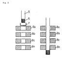
- Fig. 3 is a sectional view explaining the processing method of a battery can used in a battery according to an embodiment of the invention.
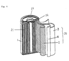
- Fig. 4 is a perspective view showing a structure of a battery according to an embodiment of the invention.
- FIG. 4 A perspective view of a battery according to an embodiment of the invention is shown in Fig. 4.
- the battery is composed of a battery can 1, an electrode group 20 contained in the battery can 1, an electrolyte member 21 immersed in the electrode group, and a metal sealing plate 23 disposed to seal the opening of the battery can 1.
- the plate group 20 includes a positive electrode member 2, a negative electrode member 2, and a separator 4 disposed between the positive electrode member 2 and negative electrode member 3.
- the plate group 20 is wound in a spiral form, and the negative electrode member 3 is disposed on the outer circumferential side and the positive electrode member 2 on the inner circumference side thereof.
- the negative electrode member 3 is composed of a metal core and a negative electrode material covering the surface of the core.
- the positive electrode member 2, negative electrode member 3, and separator 4 are band-shaped sheets or plates, and they are wound spirally.
- a metal sealing plate 23 is disposed through an electrical insulating packing 22.
- the metal sealing plate 23 also serves as a positive terminal.
- part of the positive electrode member 2 is electrically connected to the inside of the metal sealing plate 23.
- Plural linear bumps are formed inside of the battery can 1.
- the outermost surface of the negative electrode member 3 contacts with the linear bumps of the battery can 1, and an electrical conduction is achieved by this contact.
- Fig. 1 is a horizontal sectional view of the battery can
- Fig. 2 is a vertical sectional view of the battery can.
- the battery can 1 is cylindrical in shape, and plural linear bumps 9 are formed inside of the battery can 1.
- linear bumps are formed vertically at a height of 0.05 to 0.25 mm from the bottom of the battery can and at a pitch of 0.5 to 10 mm.
- Such battery can was fabricated by the drawing and ironing (DI) technology shown in Fig. 3.
- DI drawing and ironing
- a groove 6 in a depth corresponding to the required height of bumps is formed at the leading end of a punch 5 parallel to the axial line of the punch.
- This punch 5 is abutted against a metal material 7 preliminarily formed in a cup shape by nickel plated iron plate, and the drawing and ironing dies 8a to 8n of outer pattern are passed sequentially.
- the die of which drawing and ironing diameter of the final stage 8n is the desired outside diameter of the can is pressurized by the punch 5.
- the can inside is strongly pressed against the punch peripheral surface by the pressurizing force from the die, and vertical stripes are transferred.
- the battery can forming linear bumps on the inner surface of the can was fabricated.
- the linear bumps are set in the length of the groove also in the punch so as not to reach the vicinity of the opening of the battery can.
- the fabricated nickel-cadmium storage battery is 16.3 mm in outside diameter of battery can, and 42.5 mm in height of battery.
- a nickel plated iron plate for fabricating the battery can a 0.45 mm thick plate was used. In the DI process, the can bottom is nearly same as the thickness of the plated iron plate being used, but the side surface may be made thinner. In this embodiment, the side thickness was 0.19 mm.
- the positive electrode member is composed of a core material of foamed nickel board, and an active substance mainly composed of nickel hydroxide filled in the core material.
- the negative electrode material is composed of a metal core having a conductivity, and a cadmium compound covering the surface of the core.
- a positive plate as a positive electrode member and a negative plate as a negative electrode member were put in a plate group wound spirally through a separator, and an electrolyte mainly composed of KOH was injected as the electrode member, and the opening was sealed.
- an enclosed nickel-cadmium storage battery of capacity of 1200 mAh was fabricated.
- the linear bumps of the battery can were defined in the height, pitch and length.
- various nickel-cadmium storage batteries were fabricated. Then the initial internal resistance was measured. Afterwards, the storage battery was dropped on an oak board of 10 mm or more in thickness, from a height of 20 cm, five times in the battery axial direction and five times in the direction vertical to the axial line. The internal resistance after dropping was also measured. Comparing the internal resistance before dropping and after dropping, it was confirmed that the elevation of the internal resistance was suppressed within 5 mohms or less.
- Various battery cans and various batteries were manufactured by forming linear bumps in various lengths, heights and pitches.
- the internal resistance was measured after initial charging and discharging, and the internal resistance was measured after the drop test, and the difference of the internal resistance before and after dropping was calculated.
- the initial internal resistance before dropping was about 21 mohms to about 25 mohms.
- the internal resistance was as follows.
- the internal resistance after dropping test of the battery using the battery can with the linear bump length of 37 mm, bump pitch of 2.08 mm and bump height of 0.14 mm was 21 mohms to 26 mohms, or 23 mohms in average.
- the internal resistance after dropping test of the battery using the battery can with the linear bump length of 37 mm, bump pitch of 0.33 mm and bump height of 0.03 mm was 21 mohms to 31 mohms, or 25 mohms in average.
- the internal resistance after dropping test of the battery using the battery can with the linear bump length of 37 mm, bump pitch of 16.7 mm and bump height of 0.03 mm was 23 mohms to 40 mohms or 27 mohms in average.
- the internal resistance after dropping test of the battery using the battery can with the linear bump length of 37 mm, bump pitch of 16.7 mm and bump height of 0.14 mm was 21 mohms to 29 mohms, or 25 mohms in average.
- the internal resistance after dropping test of the battery using the battery can with the linear bump length of 37 mm, bump pitch of 2.08 mm and bump height of 0.03 mm was 22 mohms to 36 mohms, or 26 mohms in average.
- the internal resistance after dropping test of the battery using the battery can with the linear bump length of 37 mm, bump pitch of 0.33 mm and bump height of 0.14 mm was 21 mohms to 29 mohms, or 25 mohms in average.
- the linear bump pitch was 0.5 mm or less or 10 mm or more, or the linear bump height was 0.05 mm or less, the internal resistance value was not stable, and the deviation tended to be larger.
- the linear bump length in the battery can is 37 mm, and the bump height is shown in horizontal lines and the pitch is given in the vertical columns.
- the "-" mark refers to an item that is not measured, including a case in which the punch could not be manufactured.
- the " ⁇ ” mark shows the elevation of internal resistance was within 5 mohms in all of 50 cells. The figure shows the number of cells of which internal resistance exceeded 5 mohms.
- the bump height does not exceed 0.26 mm.
- the pitch in a range of 0.5 mm to 10.0 mm and bump height of 0.09 mm or more, all are “ ⁇ ” marked. If the bump height is 0.05 mm, it is " ⁇ " depending on the pitch condition.
- the length of the linear bumps in the battery can is 30 mm, and in Table 3, it is 20 mm.
- Table 1, Table 2, and Table 3 in the constitution of forming the linear bumps on the surface in the battery can and forming the bumps so as to bite into or compress the surface of the negative electrode member, it is effective to suppress elevation of internal resistance due to external impact. In particular, an excellent effect is obtained when the linear bumps have a specified pitch and height.
- Table 1, Table 2, and Table 3 when the height of the linear bumps is in a range of 0.05 mm to 0.25 mm, and the pitch of linear bumps is in a range of 0.5 mm to 10 mm, the effect of suppressing elevation of internal resistance due to dropping is obtained.
- the linear bump height is less than 0.05 mm and the pitch is less than 0.5 mm, the force of pressurizing the negative plate by the linear bumps is weak, and the contact force between the negative plate and linear bumps is weak and the contact resistance is high, so that the effect for suppressing elevation of internal resistance due to dropping is smaller.
- the pitch is 10 mm or more, the contact surface area of the negative plate and linear bumps is small, and the amount of change of contact resistance due to impact from outside is larger, so that the effect of suppressing the elevation of internal resistance due to dropping is smaller.
- the height of the linear bumps may be 0.25 mm or more.
- the height of linear bumps is preferred to be 0.26 mm or less. If more than 0.26 mm, the pressurizing force of the negative plate and linear bumps increases, and the effect for suppressing elevation of internal resistance due to dropping also becomes larger, but as the effect for suppressing elevation of internal loss is saturated, to the contrary, the volume for installing the plate group is decreased.
- the shape of the linear bumps is not particularly limited, but the shape likely to bite into the negative electrode material is preferred, or the shape easy to compress is desired, and, for example, the sectional shape of the bumps may be an acute triangle, an obtuse triangle, a circle, a semi-circle, a trapezoid, or a quadrangle.
- the conductivity of the negative electrode material for composing the negative electrode member is desired to be smaller than the conductivity of the metal core. In this constitution, the effect for decreasing the internal resistance is further enhanced.
- the DI can is presented, but same effects are obtained in other battery cans such as drawn cans.
- the nickel-cadmium storage battery is shown, but same effects are obtained in other spiral batteries such as nickel-hydrogen battery and lithium secondary battery.
- the negative electrode material an example of cadmium compound is shown, but not limited to this, for example, hydrogen occluded alloy, lithium metal of lithium secondary battery, lithium alloy, or carbon material capable of intercalating lithium may be used.
- the constitution of the invention it is possible to obtain a battery simultaneously having various characteristics including small internal resistance, high capacity in a limited external volume, and excellent reliability against external impact.
Landscapes
- Chemical & Material Sciences (AREA)
- Chemical Kinetics & Catalysis (AREA)
- Electrochemistry (AREA)
- General Chemical & Material Sciences (AREA)
- Engineering & Computer Science (AREA)
- Manufacturing & Machinery (AREA)
- Mechanical Engineering (AREA)
- Sealing Battery Cases Or Jackets (AREA)
- Secondary Cells (AREA)
- Connection Of Batteries Or Terminals (AREA)
Abstract
Description
- The present invention relates to a battery can for storing a spiral plate group of a battery, in particular, an enclosed type alkaline storage battery.
- Recently, in the rapid progress in portable and cordless appliances, there is a mounting demand for the secondary battery of small size and light weight and having a high energy density as the power source of these appliances. In particular, the lithium secondary battery and nickel-hydrogen storage battery are highly expected, and many new products are developed. Besides, in the nickel-cadmium storage battery which is low in cost and high in reliability, a further enhancement of characteristic is desired.
- A conventional nickel-cadmium battery is composed of a battery can, a plate group contained in the battery can, and an electrolytic member. The inner wall of the battery can is a smooth surface, so that the spiral plate group can be inserted easily. The plate group comprises a positive plate, a negative plate, and a separator. The plate group is spiral, and the negative plate is positioned on the outermost circumference, and this negative plate contacts with the inner wall of the battery can. That is, the battery can serves also as the negative terminal. The plate group is only wound, and the lead of the negative plate is not spot-welded or bonded to the bottom of the battery can. In this structure, therefore, since the inner wall of the battery can confronting the outermost circumference of the negative plate is a smooth surface, the negative plate and battery can only contact with each other, and the contact pressure is small, and hence the internal resistance of the battery is often heightened. Besides, the plate group is likely to be moved by an external impact, and the internal resistance is not stabilized, and, as a result, when the internal resistance is large, sufficient charging or discharging cannot be conducted.
- To reduce the internal resistance of an alkaline manganese battery, in Japanese Patent Publication No. 7-99686, it is proposed to form fine vertical stripes on the inner surface of the can. However, in the case of the alkaline manganese battery in which the positive electrode compound directly contacts with the inner surface of the can, it is effective to form vertical stripes at protrusion height of 0.005 to 0.02 mm and stripe pitch of 0.002 to 0.4 mm as disclosed therein, but in the case of the battery in which contact between the negative plate and the inner wall of the battery can must be maintained only by inserting a spiral plate group composed by winding a positive plate and a negative plate around a separator into the battery can, a negative compound material of high resistance value is interposed between the negative plate on the outermost circumference of the spiral plate group and the inner surface of the battery can. Accordingly, if the vertical stripe pitch is less than 0.4 mm, the contact surface area of the battery can and negative electrode material is increased, but the material resistance of the negative electrode material is high, and hence the effect for reducing the internal resistance of the battery and the effect for suppressing changes of internal resistance due to external impact are small.
- The battery of the invention comprises a battery can having a conductivity, serving also as a negative terminal, and including an opening, an electrode group disposed in the battery can, an electrolyte member disposed in the battery can, and a sealing member serving also as a positive terminal, disposed in the opening of the battery can through an electric insulating member. The electrode group includes a positive electrode member, a negative electrode member, and a separator disposed between the positive electrode member and the negative electrode member, the electrode group is wound and disposed in a spiral state so that the negative electrode member may be positioned at the outside and that the positive electrode member may be positioned at the inside. The negative electrode member has a metal core and a negative electrode material covering the surface of the metal core. A part of the positive electrode member electrically conducts with the sealing member. Plural bumps are formed inside of the battery can. The plural bumps are disposed in a contacting state while pressurizing the negative electrode member positioned on the outermost circumference of the electrode group in spiral state, and each bump of the plural bumps is disposed in a state of covering the surface of the negative electrode member.
- In this constitution, preferably, the battery can is a cylindrical battery can. Preferably, the plural bumps are plural linear bumps formed vertically to the bottom of the battery can. Preferably, the pitch between linear bumps of the plural linear bumps ranges from 0.5 mm to 10 mm. Preferably, the height of each linear bump of the plural linear bumps ranges from 0.05 mm to 0.25 mm. Preferably, the conductivity of the negative electrode material is smaller than the conductivity of the metal core.
- In this constitution, since the bumps strongly pressurize the surface of the negative electrode member, and the negative electrode member is firmly fixed to the bumps of the battery can, if an external impact is given, the plate group is not deviated and moved, so that change or elevation of internal resistance may be suppressed. Moreover, the bumps strongly pressurize the surface of the negative electrode member. By this pressurizing force, the bumps deeply bite into the negative electrode material having a conductivity covering the surface of the negative electrode member. Alternatively, the bumps compress the negative electrode material having conductivity covering the surface of the negative electrode member. Accordingly, the deviation of the internal resistance value is small, and a stable internal resistance is obtained. Besides, the distance between the metal core and the bumps composed inside of the negative electrode member is shortened. As a result, the resistance between the negative electrode member and the bumps as negative terminals is reduced, and the internal resistance becomes smaller.
- Moreover, when the thickness of the material plate of the battery can and the outside diameter of the battery can are constant, the above effects are obtained without lowering the effective capacity in the battery can. Thus, while maintaining a high capacity in a limited outer shape of small internal resistance, a battery having an excellent reliability hardly changing in the resistance against external impact is obtained.
- Fig. 1 is a horizontal sectional view of a battery can according to an embodiment of the invention.
- Fig. 2 is a vertical sectional view of a battery can according to an embodiment of the invention.
- Fig. 3 is a sectional view explaining the processing method of a battery can used in a battery according to an embodiment of the invention.
- Fig. 4 is a perspective view showing a structure of a battery according to an embodiment of the invention.
-
- 1
- Battery can
- 2
- Positive member
- 3
- Negative member
- 4
- Separator
- 5
- Punch
- 6
- Punch groove
- 7
- Cup-shaped metal material
- 8
- Drawing and ironing die
- 9
- Linear bump
- A perspective view of a battery according to an embodiment of the invention is shown in Fig. 4. In Fig. 4, the battery is composed of a battery can 1, an
electrode group 20 contained in the battery can 1, anelectrolyte member 21 immersed in the electrode group, and ametal sealing plate 23 disposed to seal the opening of the battery can 1. Theplate group 20 includes a positive electrode member 2, a negative electrode member 2, and aseparator 4 disposed between the positive electrode member 2 andnegative electrode member 3. Theplate group 20 is wound in a spiral form, and thenegative electrode member 3 is disposed on the outer circumferential side and the positive electrode member 2 on the inner circumference side thereof. Thenegative electrode member 3 is composed of a metal core and a negative electrode material covering the surface of the core. That is, the positive electrode member 2,negative electrode member 3, andseparator 4 are band-shaped sheets or plates, and they are wound spirally. At the opening of the battery can 1, ametal sealing plate 23 is disposed through an electrical insulatingpacking 22. Themetal sealing plate 23 also serves as a positive terminal. Of theelectrode group 20 wound spirally, part of the positive electrode member 2 is electrically connected to the inside of themetal sealing plate 23. Plural linear bumps are formed inside of the battery can 1. Of theelectrode group 20 wound spirally, the outermost surface of thenegative electrode member 3 contacts with the linear bumps of the battery can 1, and an electrical conduction is achieved by this contact. - Examples of the battery can being used are shown in Fig. 1 and Fig. 2. Fig. 1 is a horizontal sectional view of the battery can, and Fig. 2 is a vertical sectional view of the battery can. In Fig. 1 and Fig. 2, the battery can 1 is cylindrical in shape, and plural
linear bumps 9 are formed inside of the battery can 1. - In the inner wall of the battery can 1, linear bumps are formed vertically at a height of 0.05 to 0.25 mm from the bottom of the battery can and at a pitch of 0.5 to 10 mm. Such battery can was fabricated by the drawing and ironing (DI) technology shown in Fig. 3. In Fig. 3, a
groove 6 in a depth corresponding to the required height of bumps is formed at the leading end of apunch 5 parallel to the axial line of the punch. Thispunch 5 is abutted against ametal material 7 preliminarily formed in a cup shape by nickel plated iron plate, and the drawing and ironing dies 8a to 8n of outer pattern are passed sequentially. The die of which drawing and ironing diameter of thefinal stage 8n is the desired outside diameter of the can is pressurized by thepunch 5. At this time, the can inside is strongly pressed against the punch peripheral surface by the pressurizing force from the die, and vertical stripes are transferred. In this way, the battery can forming linear bumps on the inner surface of the can was fabricated. In this case, the linear bumps are set in the length of the groove also in the punch so as not to reach the vicinity of the opening of the battery can. - The fabricated nickel-cadmium storage battery is 16.3 mm in outside diameter of battery can, and 42.5 mm in height of battery. As a nickel plated iron plate for fabricating the battery can, a 0.45 mm thick plate was used. In the DI process, the can bottom is nearly same as the thickness of the plated iron plate being used, but the side surface may be made thinner. In this embodiment, the side thickness was 0.19 mm. The positive electrode member is composed of a core material of foamed nickel board, and an active substance mainly composed of nickel hydroxide filled in the core material. The negative electrode material is composed of a metal core having a conductivity, and a cadmium compound covering the surface of the core.
- In the battery can shown in Fig. 1, a positive plate as a positive electrode member and a negative plate as a negative electrode member were put in a plate group wound spirally through a separator, and an electrolyte mainly composed of KOH was injected as the electrode member, and the opening was sealed. Thus, an enclosed nickel-cadmium storage battery of capacity of 1200 mAh was fabricated.
- The linear bumps of the battery can were defined in the height, pitch and length. In this method, various nickel-cadmium storage batteries were fabricated. Then the initial internal resistance was measured. Afterwards, the storage battery was dropped on an oak board of 10 mm or more in thickness, from a height of 20 cm, five times in the battery axial direction and five times in the direction vertical to the axial line. The internal resistance after dropping was also measured. Comparing the internal resistance before dropping and after dropping, it was confirmed that the elevation of the internal resistance was suppressed within 5 mohms or less.
- Various battery cans and various batteries were manufactured by forming linear bumps in various lengths, heights and pitches. In 50 cells each of the manufactured batteries, the internal resistance was measured after initial charging and discharging, and the internal resistance was measured after the drop test, and the difference of the internal resistance before and after dropping was calculated.
- The initial internal resistance before dropping was about 21 mohms to about 25 mohms. On the other hand, after the dropping test, the internal resistance was as follows.
- The internal resistance after dropping test of the battery using the battery can with the linear bump length of 37 mm, bump pitch of 2.08 mm and bump height of 0.14 mm was 21 mohms to 26 mohms, or 23 mohms in average.
- The internal resistance after dropping test of the battery using the battery can with the linear bump length of 37 mm, bump pitch of 0.33 mm and bump height of 0.03 mm was 21 mohms to 31 mohms, or 25 mohms in average.
- The internal resistance after dropping test of the battery using the battery can with the linear bump length of 37 mm, bump pitch of 16.7 mm and bump height of 0.03 mm was 23 mohms to 40 mohms or 27 mohms in average.
- The internal resistance after dropping test of the battery using the battery can with the linear bump length of 37 mm, bump pitch of 16.7 mm and bump height of 0.14 mm was 21 mohms to 29 mohms, or 25 mohms in average.
- The internal resistance after dropping test of the battery using the battery can with the linear bump length of 37 mm, bump pitch of 2.08 mm and bump height of 0.03 mm was 22 mohms to 36 mohms, or 26 mohms in average.
- The internal resistance after dropping test of the battery using the battery can with the linear bump length of 37 mm, bump pitch of 0.33 mm and bump height of 0.14 mm was 21 mohms to 29 mohms, or 25 mohms in average.
- Thus, when the linear bump pitch was 0.5 mm or less or 10 mm or more, or the linear bump height was 0.05 mm or less, the internal resistance value was not stable, and the deviation tended to be larger.
- Results of measurement of difference of internal resistance before and after dropping in various batteries are shown in Table 1, Table 2, and Table 3.


- In the batteries in Table 1. the linear bump length in the battery can is 37 mm, and the bump height is shown in horizontal lines and the pitch is given in the vertical columns. The "-" mark refers to an item that is not measured, including a case in which the punch could not be manufactured. The "○" mark shows the elevation of internal resistance was within 5 mohms in all of 50 cells. The figure shows the number of cells of which internal resistance exceeded 5 mohms. In Table 1, since the thickness of the nickel plated iron plate is 0.45 mm, and the thickness of the formed battery can is 0.19 mm, the bump height does not exceed 0.26 mm. In the case of the pitch in a range of 0.5 mm to 10.0 mm and bump height of 0.09 mm or more, all are "○" marked. If the bump height is 0.05 mm, it is "○" depending on the pitch condition.
- In Table 2, the length of the linear bumps in the battery can is 30 mm, and in Table 3, it is 20 mm. As clear from Table 1, Table 2, and Table 3, in the constitution of forming the linear bumps on the surface in the battery can and forming the bumps so as to bite into or compress the surface of the negative electrode member, it is effective to suppress elevation of internal resistance due to external impact. In particular, an excellent effect is obtained when the linear bumps have a specified pitch and height. Also as known from Table 1, Table 2, and Table 3, when the height of the linear bumps is in a range of 0.05 mm to 0.25 mm, and the pitch of linear bumps is in a range of 0.5 mm to 10 mm, the effect of suppressing elevation of internal resistance due to dropping is obtained. When the linear bump height is less than 0.05 mm and the pitch is less than 0.5 mm, the force of pressurizing the negative plate by the linear bumps is weak, and the contact force between the negative plate and linear bumps is weak and the contact resistance is high, so that the effect for suppressing elevation of internal resistance due to dropping is smaller. When the pitch is 10 mm or more, the contact surface area of the negative plate and linear bumps is small, and the amount of change of contact resistance due to impact from outside is larger, so that the effect of suppressing the elevation of internal resistance due to dropping is smaller. Besides, by controlling the thickness of the battery can and the thickness of the nickel plated pole plate, the height of the linear bumps may be 0.25 mm or more. When the thickness of the battery can is about 0.45 mm, the height of linear bumps is preferred to be 0.26 mm or less. If more than 0.26 mm, the pressurizing force of the negative plate and linear bumps increases, and the effect for suppressing elevation of internal resistance due to dropping also becomes larger, but as the effect for suppressing elevation of internal loss is saturated, to the contrary, the volume for installing the plate group is decreased. The shape of the linear bumps is not particularly limited, but the shape likely to bite into the negative electrode material is preferred, or the shape easy to compress is desired, and, for example, the sectional shape of the bumps may be an acute triangle, an obtuse triangle, a circle, a semi-circle, a trapezoid, or a quadrangle. The conductivity of the negative electrode material for composing the negative electrode member is desired to be smaller than the conductivity of the metal core. In this constitution, the effect for decreasing the internal resistance is further enhanced.
- In this embodiment, the DI can is presented, but same effects are obtained in other battery cans such as drawn cans. Also in the embodiment, the nickel-cadmium storage battery is shown, but same effects are obtained in other spiral batteries such as nickel-hydrogen battery and lithium secondary battery. As the negative electrode material, an example of cadmium compound is shown, but not limited to this, for example, hydrogen occluded alloy, lithium metal of lithium secondary battery, lithium alloy, or carbon material capable of intercalating lithium may be used. As the positive electrode material, an example of nickel compound is presented, but not limited to this, for example, lithium transition metal of lithium secondary battery (such as LiMO2, M=Co, Ni, or CoMn) and spinel LiMo204 may be also used.
- Thus, according to the constitution of the invention, it is possible to obtain a battery simultaneously having various characteristics including small internal resistance, high capacity in a limited external volume, and excellent reliability against external impact.
Claims (13)
- A battery comprising:a battery can having a conductivity, serving also as a negative terminal, and including an opening,an electrode group disposed in said battery can,an electrolyte member disposed in said battery can, anda sealing member serving also as a positive terminal, disposed in said opening of said battery can through an electric insulating member,wherein said electrode group includes a positive electrode member, a negative electrode member, and a separator disposed between said positive electrode member and said negative electrode member,said electrode group is wound and disposed in a spiral state so that said negative electrode member may be positioned at the outside and that said positive electrode member may be positioned at the inside,part of said positive electrode member electrically conducts with said sealing member,plural bumps are formed inside of said battery can,said plural bumps are disposed in a contacting state while pressurizing said negative electrode member positioned on the outermost circumference of said electrode group in spiral state, andeach bump of said plural bumps is disposed in a state of sinking into the surface of said negative electrode member.
- A battery of claim 1, wherein said state of each bump of said plural bumps sinking into the surface of said negative electrode member is a state of each bump biting into the surface of said negative electrode member.
- A battery of claim 1, wherein said state of each bump of said plural bumps sinking into the surface of said negative electrode member is a state of each bump compressing the surface of said negative electrode member.
- A battery of claim 1, wherein said negative electrode member includes a metal core material and a negative electrode material covering the surface of said metal core material, and each bump of said plural bumps are disposed in a state of sinking into the surface of said negative electrode material.
- A battery of claim 1, wherein said battery can is a cylindrical battery can.
- A battery of claim 1, wherein said plural bumps are plural linear bumps formed vertically to the bottom of said battery can.
- A battery of claim 1, wherein said plural bumps are plural linear bumps formed vertically to the bottom of said battery can, and the pitch between linear bumps of said plural linear bumps ranges from 0.5 mm to 10 mm.
- A battery of claim 1, wherein said plural bumps are plural linear bumps formed vertically to the bottom of said battery can, and the height of each linear bump of said plural linear bumps ranges from 0.05 mm to 0.25 mm.
- A battery of claim 1, wherein said battery can is a cylindrical battery can, each bump of said plural bumps is a linear bump formed vertically to the bottom of said cylindrical battery can, and the height of each linear bump ranges from 0.05 mm to 0.25 mm.
- A battery of claim 1, wherein said battery can is a cylindrical battery can, said plural bumps are plural linear bumps formed vertically to the bottom of said cylindrical battery can, the pitch between linear bumps of said plural linear bumps ranges from 0.5 mm to 10 mm, and the height of each linear bump ranges from 0.05 mm to 0.25 mm.
- A battery of claim 1, wherein said battery can confronting said electric insulating member is a nearly smooth surface.
- A battery of claim 4, wherein said metal core member has a conductivity smaller than that of the negative electrode material.
- A battery comprising:a battery can having a conductivity, serving also as a negative terminal, and including an opening,a spiral electrode group disposed in said battery can, and winding a positive plate and a negative plate through a separator,an electrolyte member disposed in said battery can, anda sealing member serving also as a positive terminal, disposed in said opening of said battery can through an electric insulating member,wherein plural linear bumps vertical to the bottom of said battery can are formed in the inner wall of said battery can contacting with the negative electrode positioned on the outermost circumference of said plate group,the height of each linear bump of said plural linear bumps ranges from 0.05 mm to 0.25 mm,the pitch between linear bumps ranges from 0.5 mm to 10 mm, andthe portion of each linear bump confronting said electric insulating member is nearly a smooth surface.
Applications Claiming Priority (3)
| Application Number | Priority Date | Filing Date | Title |
|---|---|---|---|
| JP2226896 | 1996-02-08 | ||
| JP22268/96 | 1996-02-08 | ||
| JP02226896A JP3402047B2 (en) | 1996-02-08 | 1996-02-08 | Battery |
Publications (2)
| Publication Number | Publication Date |
|---|---|
| EP0788176A1 true EP0788176A1 (en) | 1997-08-06 |
| EP0788176B1 EP0788176B1 (en) | 2001-07-04 |
Family
ID=12078030
Family Applications (1)
| Application Number | Title | Priority Date | Filing Date |
|---|---|---|---|
| EP97300818A Expired - Lifetime EP0788176B1 (en) | 1996-02-08 | 1997-02-07 | Battery |
Country Status (5)
| Country | Link |
|---|---|
| US (1) | US6007936A (en) |
| EP (1) | EP0788176B1 (en) |
| JP (1) | JP3402047B2 (en) |
| DE (1) | DE69705436T2 (en) |
| ID (1) | ID15884A (en) |
Cited By (4)
| Publication number | Priority date | Publication date | Assignee | Title |
|---|---|---|---|---|
| WO1999025040A1 (en) * | 1997-11-06 | 1999-05-20 | Bondface Technology Inc. | Method of treating a tubular member |
| WO2001020692A1 (en) * | 1999-09-14 | 2001-03-22 | Eveready Battery Company, Inc. | Electrochemical cell having beaded can and method of forming same |
| EP1347519A4 (en) * | 2000-12-26 | 2007-05-02 | Matsushita Electric Industrial Co Ltd | SQUARE BATTERY HOUSING, MANUFACTURING METHOD, AND SQUARE BATTERY USING THE SAME |
| EP1286402A4 (en) * | 2000-04-28 | 2009-05-27 | Panasonic Corp | CELLULAR TUBE AND METHOD FOR MANUFACTURING THE SAME |
Families Citing this family (12)
| Publication number | Priority date | Publication date | Assignee | Title |
|---|---|---|---|---|
| JP3604879B2 (en) * | 1997-08-05 | 2004-12-22 | 松下電器産業株式会社 | Battery manufacturing method |
| JP4594460B2 (en) * | 1999-03-31 | 2010-12-08 | 株式会社東芝 | Non-aqueous electrolyte secondary battery |
| US6482543B1 (en) * | 2000-06-13 | 2002-11-19 | The Gillette Company | Alkaline cell with improved cathode and current collector configuration |
| US7045247B1 (en) * | 2000-08-24 | 2006-05-16 | The Gillette Company | Battery cathode |
| JP3740048B2 (en) * | 2001-10-12 | 2006-01-25 | 松下電器産業株式会社 | Battery can and battery using the same |
| US20050079411A1 (en) * | 2003-10-08 | 2005-04-14 | Truelove & Maclean, Incorporated | Drawn and grooved battery can |
| US8721743B2 (en) * | 2004-10-21 | 2014-05-13 | The Gillette Company | Battery cathodes |
| KR100778980B1 (en) * | 2005-12-29 | 2007-11-22 | 삼성에스디아이 주식회사 | Lithium secondary battery |
| US8053101B2 (en) * | 2005-12-29 | 2011-11-08 | Samsung Sdi Co., Ltd. | Lithium ion rechargeable battery |
| KR100973309B1 (en) * | 2007-12-13 | 2010-07-30 | 삼성에스디아이 주식회사 | Insulation case for secondary battery and secondary battery having same |
| JP5677868B2 (en) * | 2011-02-07 | 2015-02-25 | Fdkエナジー株式会社 | Battery can for cylindrical alkaline battery and cylindrical alkaline battery |
| JP7055609B2 (en) | 2017-09-26 | 2022-04-18 | 株式会社東芝 | Square secondary battery, battery module, power storage device, vehicle and projectile |
Citations (6)
| Publication number | Priority date | Publication date | Assignee | Title |
|---|---|---|---|---|
| DE3011563A1 (en) * | 1979-03-29 | 1980-10-09 | Gen Electric | VIBRATION-RESISTANT ELECTROCHEMICAL CELL WITH A DEFORMED HOUSING AND METHOD FOR THE PRODUCTION THEREOF |
| US4553419A (en) * | 1982-03-29 | 1985-11-19 | Duracell Inc. | Process for forming cell cans having internal longitudinal ribs |
| JPS61101951A (en) * | 1984-10-23 | 1986-05-20 | Shin Kobe Electric Mach Co Ltd | Manufacturing cylindrical enclosed-type alkali storage cell |
| JPH03254074A (en) * | 1990-03-02 | 1991-11-13 | Japan Storage Battery Co Ltd | Battery with organic electrolytic solution |
| JPH04160763A (en) * | 1990-10-22 | 1992-06-04 | Toshiba Battery Co Ltd | Nickel hydrogen secondary battery |
| JPH06150973A (en) * | 1992-11-04 | 1994-05-31 | Nippon Telegr & Teleph Corp <Ntt> | Nonaqueous electrolyte secondary battery |
Family Cites Families (5)
| Publication number | Priority date | Publication date | Assignee | Title |
|---|---|---|---|---|
| US3081367A (en) * | 1961-05-10 | 1963-03-12 | Sonotone Corp | Electrode assembly for sealed rechargeable alkaline battery cells |
| JPS5834694Y2 (en) * | 1979-04-16 | 1983-08-04 | 三洋電機株式会社 | battery |
| JPH0799686B2 (en) * | 1984-02-28 | 1995-10-25 | 松下電器産業株式会社 | Battery |
| US4929519A (en) * | 1989-07-20 | 1990-05-29 | Gates Energy Products, Inc. | Wound electrode assembly for an electrochemical cell |
| JP2785237B2 (en) * | 1993-09-28 | 1998-08-13 | キヤノン株式会社 | Wireless communication device |
-
1996
- 1996-02-08 JP JP02226896A patent/JP3402047B2/en not_active Expired - Fee Related
-
1997
- 1997-02-05 ID IDP970345A patent/ID15884A/en unknown
- 1997-02-07 DE DE69705436T patent/DE69705436T2/en not_active Expired - Fee Related
- 1997-02-07 EP EP97300818A patent/EP0788176B1/en not_active Expired - Lifetime
- 1997-02-07 US US08/796,293 patent/US6007936A/en not_active Expired - Lifetime
Patent Citations (6)
| Publication number | Priority date | Publication date | Assignee | Title |
|---|---|---|---|---|
| DE3011563A1 (en) * | 1979-03-29 | 1980-10-09 | Gen Electric | VIBRATION-RESISTANT ELECTROCHEMICAL CELL WITH A DEFORMED HOUSING AND METHOD FOR THE PRODUCTION THEREOF |
| US4553419A (en) * | 1982-03-29 | 1985-11-19 | Duracell Inc. | Process for forming cell cans having internal longitudinal ribs |
| JPS61101951A (en) * | 1984-10-23 | 1986-05-20 | Shin Kobe Electric Mach Co Ltd | Manufacturing cylindrical enclosed-type alkali storage cell |
| JPH03254074A (en) * | 1990-03-02 | 1991-11-13 | Japan Storage Battery Co Ltd | Battery with organic electrolytic solution |
| JPH04160763A (en) * | 1990-10-22 | 1992-06-04 | Toshiba Battery Co Ltd | Nickel hydrogen secondary battery |
| JPH06150973A (en) * | 1992-11-04 | 1994-05-31 | Nippon Telegr & Teleph Corp <Ntt> | Nonaqueous electrolyte secondary battery |
Non-Patent Citations (4)
| Title |
|---|
| PATENT ABSTRACTS OF JAPAN vol. 010, no. 283 (E - 440) 26 September 1986 (1986-09-26) * |
| PATENT ABSTRACTS OF JAPAN vol. 016, no. 052 (E - 1164) 10 February 1992 (1992-02-10) * |
| PATENT ABSTRACTS OF JAPAN vol. 016, no. 453 (E - 1267) 21 September 1992 (1992-09-21) * |
| PATENT ABSTRACTS OF JAPAN vol. 018, no. 458 (E - 1596) 25 August 1994 (1994-08-25) * |
Cited By (5)
| Publication number | Priority date | Publication date | Assignee | Title |
|---|---|---|---|---|
| WO1999025040A1 (en) * | 1997-11-06 | 1999-05-20 | Bondface Technology Inc. | Method of treating a tubular member |
| WO2001020692A1 (en) * | 1999-09-14 | 2001-03-22 | Eveready Battery Company, Inc. | Electrochemical cell having beaded can and method of forming same |
| US6251536B1 (en) * | 1999-09-14 | 2001-06-26 | Eveready Battery Company, Inc. | Electrochemical cell having beaded can |
| EP1286402A4 (en) * | 2000-04-28 | 2009-05-27 | Panasonic Corp | CELLULAR TUBE AND METHOD FOR MANUFACTURING THE SAME |
| EP1347519A4 (en) * | 2000-12-26 | 2007-05-02 | Matsushita Electric Industrial Co Ltd | SQUARE BATTERY HOUSING, MANUFACTURING METHOD, AND SQUARE BATTERY USING THE SAME |
Also Published As
| Publication number | Publication date |
|---|---|
| DE69705436T2 (en) | 2001-10-18 |
| DE69705436D1 (en) | 2001-08-09 |
| JP3402047B2 (en) | 2003-04-28 |
| JPH09219180A (en) | 1997-08-19 |
| US6007936A (en) | 1999-12-28 |
| EP0788176B1 (en) | 2001-07-04 |
| ID15884A (en) | 1997-08-14 |
Similar Documents
| Publication | Publication Date | Title |
|---|---|---|
| EP0788176B1 (en) | Battery | |
| EP1145342B1 (en) | High rate electrochemical cell and assembly method | |
| US20120276429A1 (en) | Spirally-rolled electrodes with separator and the batteries therewith | |
| JP3709134B2 (en) | Square battery | |
| US7666548B2 (en) | Can type secondary battery | |
| US7432018B2 (en) | Cylindrical alkaline storage battery | |
| US6081992A (en) | Electrochemical cell formed with big mouth open end can | |
| JP3301798B2 (en) | Battery | |
| WO2001084647A1 (en) | Cell tube and method of manufacturing the cell tube | |
| KR100646530B1 (en) | Secondary battery | |
| JP3749127B2 (en) | Sealed battery and method of manufacturing sealed battery | |
| KR101264425B1 (en) | Cap assembly and rechargeable battery using the same | |
| KR100601522B1 (en) | Lithium-ion Secondary Battery | |
| JP3166487B2 (en) | Thin battery | |
| JP3588249B2 (en) | Alkaline storage battery and method for manufacturing the same | |
| KR100614355B1 (en) | Lithium-ion Secondary Battery | |
| WO2000013246A1 (en) | Method of forming a terminal pip protrusion on the casing of an alkaline cell | |
| JP2002298824A (en) | Sealed storage battery and method of manufacturing the same | |
| JP2804557B2 (en) | Prismatic battery and method of manufacturing the same | |
| JPH0773860A (en) | Manufacture of square alkaline battery | |
| JP2005056675A (en) | Cylindrical alkaline battery | |
| JP2002279941A (en) | Prismatic battery | |
| JP2000030688A (en) | Wound alkaline storage battery and method for producing the same | |
| JP2001266930A (en) | Cylindrical nickel/hydrogen secondary battery | |
| JPH1125931A (en) | Battery |
Legal Events
| Date | Code | Title | Description |
|---|---|---|---|
| PUAI | Public reference made under article 153(3) epc to a published international application that has entered the european phase |
Free format text: ORIGINAL CODE: 0009012 |
|
| AK | Designated contracting states |
Kind code of ref document: A1 Designated state(s): BE DE FR GB |
|
| 17P | Request for examination filed |
Effective date: 19980216 |
|
| 17Q | First examination report despatched |
Effective date: 19980916 |
|
| GRAG | Despatch of communication of intention to grant |
Free format text: ORIGINAL CODE: EPIDOS AGRA |
|
| GRAG | Despatch of communication of intention to grant |
Free format text: ORIGINAL CODE: EPIDOS AGRA |
|
| GRAH | Despatch of communication of intention to grant a patent |
Free format text: ORIGINAL CODE: EPIDOS IGRA |
|
| GRAH | Despatch of communication of intention to grant a patent |
Free format text: ORIGINAL CODE: EPIDOS IGRA |
|
| GRAA | (expected) grant |
Free format text: ORIGINAL CODE: 0009210 |
|
| AK | Designated contracting states |
Kind code of ref document: B1 Designated state(s): BE DE FR GB |
|
| REF | Corresponds to: |
Ref document number: 69705436 Country of ref document: DE Date of ref document: 20010809 |
|
| ET | Fr: translation filed | ||
| REG | Reference to a national code |
Ref country code: GB Ref legal event code: IF02 |
|
| PLBE | No opposition filed within time limit |
Free format text: ORIGINAL CODE: 0009261 |
|
| STAA | Information on the status of an ep patent application or granted ep patent |
Free format text: STATUS: NO OPPOSITION FILED WITHIN TIME LIMIT |
|
| 26N | No opposition filed | ||
| PGFP | Annual fee paid to national office [announced via postgrant information from national office to epo] |
Ref country code: DE Payment date: 20070201 Year of fee payment: 11 |
|
| PGFP | Annual fee paid to national office [announced via postgrant information from national office to epo] |
Ref country code: GB Payment date: 20070207 Year of fee payment: 11 |
|
| PGFP | Annual fee paid to national office [announced via postgrant information from national office to epo] |
Ref country code: BE Payment date: 20070416 Year of fee payment: 11 |
|
| PGFP | Annual fee paid to national office [announced via postgrant information from national office to epo] |
Ref country code: FR Payment date: 20070208 Year of fee payment: 11 |
|
| BERE | Be: lapsed |
Owner name: *MATSUSHITA ELECTRIC INDUSTRIAL CO. LTD Effective date: 20080228 |
|
| GBPC | Gb: european patent ceased through non-payment of renewal fee |
Effective date: 20080207 |
|
| REG | Reference to a national code |
Ref country code: FR Ref legal event code: ST Effective date: 20081031 |
|
| PG25 | Lapsed in a contracting state [announced via postgrant information from national office to epo] |
Ref country code: DE Free format text: LAPSE BECAUSE OF NON-PAYMENT OF DUE FEES Effective date: 20080902 |
|
| PG25 | Lapsed in a contracting state [announced via postgrant information from national office to epo] |
Ref country code: BE Free format text: LAPSE BECAUSE OF NON-PAYMENT OF DUE FEES Effective date: 20080228 |
|
| PG25 | Lapsed in a contracting state [announced via postgrant information from national office to epo] |
Ref country code: FR Free format text: LAPSE BECAUSE OF NON-PAYMENT OF DUE FEES Effective date: 20080229 |
|
| PG25 | Lapsed in a contracting state [announced via postgrant information from national office to epo] |
Ref country code: GB Free format text: LAPSE BECAUSE OF NON-PAYMENT OF DUE FEES Effective date: 20080207 |