EP0787961A2 - Device for detecting frost formation and for eliminating it by heating, particularly for domestic refrigerator evaporators - Google Patents
Device for detecting frost formation and for eliminating it by heating, particularly for domestic refrigerator evaporators Download PDFInfo
- Publication number
- EP0787961A2 EP0787961A2 EP97100406A EP97100406A EP0787961A2 EP 0787961 A2 EP0787961 A2 EP 0787961A2 EP 97100406 A EP97100406 A EP 97100406A EP 97100406 A EP97100406 A EP 97100406A EP 0787961 A2 EP0787961 A2 EP 0787961A2
- Authority
- EP
- European Patent Office
- Prior art keywords
- frost
- evaporator
- defrosting
- microprocessor
- capacitor
- Prior art date
- Legal status (The legal status is an assumption and is not a legal conclusion. Google has not performed a legal analysis and makes no representation as to the accuracy of the status listed.)
- Ceased
Links
Images

Classifications
-
- F—MECHANICAL ENGINEERING; LIGHTING; HEATING; WEAPONS; BLASTING
- F25—REFRIGERATION OR COOLING; COMBINED HEATING AND REFRIGERATION SYSTEMS; HEAT PUMP SYSTEMS; MANUFACTURE OR STORAGE OF ICE; LIQUEFACTION SOLIDIFICATION OF GASES
- F25D—REFRIGERATORS; COLD ROOMS; ICE-BOXES; COOLING OR FREEZING APPARATUS NOT OTHERWISE PROVIDED FOR
- F25D21/00—Defrosting; Preventing frosting; Removing condensed or defrost water
- F25D21/02—Detecting the presence of frost or condensate
-
- F—MECHANICAL ENGINEERING; LIGHTING; HEATING; WEAPONS; BLASTING
- F25—REFRIGERATION OR COOLING; COMBINED HEATING AND REFRIGERATION SYSTEMS; HEAT PUMP SYSTEMS; MANUFACTURE OR STORAGE OF ICE; LIQUEFACTION SOLIDIFICATION OF GASES
- F25D—REFRIGERATORS; COLD ROOMS; ICE-BOXES; COOLING OR FREEZING APPARATUS NOT OTHERWISE PROVIDED FOR
- F25D21/00—Defrosting; Preventing frosting; Removing condensed or defrost water
- F25D21/06—Removing frost
- F25D21/08—Removing frost by electric heating
-
- F—MECHANICAL ENGINEERING; LIGHTING; HEATING; WEAPONS; BLASTING
- F25—REFRIGERATION OR COOLING; COMBINED HEATING AND REFRIGERATION SYSTEMS; HEAT PUMP SYSTEMS; MANUFACTURE OR STORAGE OF ICE; LIQUEFACTION SOLIDIFICATION OF GASES
- F25B—REFRIGERATION MACHINES, PLANTS OR SYSTEMS; COMBINED HEATING AND REFRIGERATION SYSTEMS; HEAT PUMP SYSTEMS
- F25B2700/00—Sensing or detecting of parameters; Sensors therefor
- F25B2700/11—Sensor to detect if defrost is necessary
Definitions
- This invention relates to a device for detecting frost formation and/or for eliminating it by heating, particularly for domestic refrigerator evaporators.
- Refrigerators are also known in which thermal defrosting is effected cyclically, ie independently of the quantity of frost which has formed on the evaporator. This arrangement has the drawback of consuming electricity even when defrosting is not necessary.
- An object of the present invention is to provide a single means which performs both the frost detection and heating functions.
- a further object of the present invention is to provide a device which both monitors and eliminates frost using the same means.
- the reference numeral 1 indicates a support of flexible insulating material, such as polyamide.
- a suitable material is that known commercially as KAPTON or MYLAR (or the like) manufactured for example by DU PONT and 3M.
- Two physically separate resistive tracks extending mutually parallel in a substantially castellated arrangement are applied by known methods to said support.
- the trackless face of the support 1 carrying the tracks A and B is in contact with a plastic wall 2 bounding the refrigerator preservation compartment 3, its opposite face being in contact with a conventional evaporator 4 of the refrigerator refrigeration circuit.
- the reference numeral 5 indicates an external wall of the refrigerator and 5A indicates the refrigerator thermal insulation, for example polyurethane expanded in situ, which joins together the various described components.
- the support 1 Before expanding the polyurethane in situ the support 1 is for example fixed to the evaporator with biadhesive tape at points on or along its periphery, the ends of the resistive tracks A and B are electrically connected, as shown in Figures 3 and 4, in the following manner.
- the end A1 is electrically connected to a contactor means 6 in the form of a switching means operated and controlled by a microprocessor ⁇ P.
- the end B1 is connected to earth.
- the ends A2 and B2 are connected to a contactor means 7, the purpose of which is to connect said ends together or disconnect them from each other, and is operated and controlled by the microprocessor ⁇ P.
- the contactor means 6 connects the end A1 either to a voltage source, for example at 24V, or to a node 8 to which there are connected a resistor R (connected to a voltage source at 5V) and a variable frequency oscillator OSC suitably connected to a conventional ammeter 9 feeding its signal to the microprocessor ⁇ P which processes it in known manner.
- a voltage source for example at 24V
- a resistor R connected to a voltage source at 5V
- OSC suitably connected to a conventional ammeter 9 feeding its signal to the microprocessor ⁇ P which processes it in known manner.
- the resistive tracks A and B act as the plates of a capacitor when the contactor means (6, 7) are in the position shown in Figure 4, ie during normal refrigerator operation, in which said plates define a frost detection capacitor.
- This capacitor has a certain capacitance when frost is absent from the evaporator and a different capacitance as the layer of frost grows.
- the ammeter 9 feeds differing signal values to the microprocessor ⁇ P.
- the microprocessor switches the contactor means (6, 7) into the position shown in Figure 3 in which the two tracks A and B are connected in series between the source and earth.
- the capacitor of Figure 4 is transformed into an electrical resistance heater by virtue of the resistivity of the tracks.
- the "resistor" configuration of Figure 3 varies cyclically.
- the microprocessor ⁇ P switches the contactor means (6, 7) alternately into the position shown in Figure 4 and that shown in Figure 3, so as to monitor the progress of defrosting via the ammeter 9.
Abstract
Description
- This invention relates to a device for detecting frost formation and/or for eliminating it by heating, particularly for domestic refrigerator evaporators.
- Devices for detecting frost formation on domestic refrigerator evaporators and devices for eliminating evaporator frost by heating have both existed for some time in the most varied forms.
- The former cause the latter to operate when a given frost quantity is reached on the evaporator. Their drawback is the need to provide two totally separate devices.
- Refrigerators are also known in which thermal defrosting is effected cyclically, ie independently of the quantity of frost which has formed on the evaporator. This arrangement has the drawback of consuming electricity even when defrosting is not necessary.
- An object of the present invention is to provide a single means which performs both the frost detection and heating functions.
- A further object of the present invention is to provide a device which both monitors and eliminates frost using the same means.
- These and further objects which will be more apparent from the ensuing detailed description are attained by the invention as defined by the accompanying claims.
- A preferred embodiment of the invention is described in detail hereinafter by way of non-limiting example with reference to the accompanying drawing, in which:
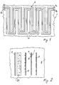
- Figure 1 is a schematic front view of the means for frost detection and/or heating to eliminate it from the evaporator;
- Figure 2 is a disassembled sectional view showing a possible location of the means of Figure 1 in relation to the evaporator region in a refrigerator;
- Figure 3 is a schematic view of the circuit arrangement in which the means of Figure 1 acts as a heater, ie as a defroster;
- Figure 4 is a schematic view of the circuit arrangement in which the means of Figure 1 acts as a capacitor, ie as a frost detector.
- In the figures, the
reference numeral 1 indicates a support of flexible insulating material, such as polyamide. A suitable material is that known commercially as KAPTON or MYLAR (or the like) manufactured for example by DU PONT and 3M. - Two physically separate resistive tracks extending mutually parallel in a substantially castellated arrangement are applied by known methods to said support.
- In the refrigerator (Figure 2), which can be static or of forced air circulation type, the trackless face of the
support 1 carrying the tracks A and B is in contact with aplastic wall 2 bounding the refrigerator preservation compartment 3, its opposite face being in contact with a conventional evaporator 4 of the refrigerator refrigeration circuit. - The
reference numeral 5 indicates an external wall of the refrigerator and 5A indicates the refrigerator thermal insulation, for example polyurethane expanded in situ, which joins together the various described components. Before expanding the polyurethane in situ thesupport 1 is for example fixed to the evaporator with biadhesive tape at points on or along its periphery, the ends of the resistive tracks A and B are electrically connected, as shown in Figures 3 and 4, in the following manner. - The end A1 is electrically connected to a contactor means 6 in the form of a switching means operated and controlled by a microprocessor µP. The end B1 is connected to earth. The ends A2 and B2 are connected to a contactor means 7, the purpose of which is to connect said ends together or disconnect them from each other, and is operated and controlled by the microprocessor µP.
- The contactor means 6 connects the end A1 either to a voltage source, for example at 24V, or to a
node 8 to which there are connected a resistor R (connected to a voltage source at 5V) and a variable frequency oscillator OSC suitably connected to aconventional ammeter 9 feeding its signal to the microprocessor µP which processes it in known manner. - The resistive tracks A and B act as the plates of a capacitor when the contactor means (6, 7) are in the position shown in Figure 4, ie during normal refrigerator operation, in which said plates define a frost detection capacitor. This capacitor has a certain capacitance when frost is absent from the evaporator and a different capacitance as the layer of frost grows. This means that the
ammeter 9 feeds differing signal values to the microprocessor µP. When the signal assumes a given value the microprocessor switches the contactor means (6, 7) into the position shown in Figure 3 in which the two tracks A and B are connected in series between the source and earth. - By this means the capacitor of Figure 4 is transformed into an electrical resistance heater by virtue of the resistivity of the tracks. The "resistor" configuration of Figure 3 varies cyclically. In other words, the microprocessor µP switches the contactor means (6, 7) alternately into the position shown in Figure 4 and that shown in Figure 3, so as to monitor the progress of defrosting via the
ammeter 9. - When defrosting has reached the desired extent (preset as reference data in the processor µP) the configuration of Figure 4 becomes stabilized, whereas if defrosting is inadequate the system switches to the configuration of Figure 3 and then of Figure 4, and so on until the desired extent of defrosting is achieved.
- A particular embodiment has been described, applied to a static refrigerator. Other embodiments can however be provided (such as one applied by suitable and obvious expedients to a forced air circulation refrigerator with an evaporator of radiator type) and are to be considered as falling within the scope of the present document.
Claims (7)
- A device for controlling the frost layer on a domestic refrigerator evaporator, characterised by comprising, in contact with the evaporator, a switchable means which when in one state acts as a frost detecting capacitor and when in another state acts as a frost heater.
- A device as claimed in claim 1, characterised in that the switchable means comprises an insulating support and at least two resistive tracks on said support.
- A device as claimed in the preceding claims, characterised in that the tracks extend parallel to each other.
- A device as claimed in one or more of the preceding claims, characterised in that the switchable means is switched by electrical contactor means controlled by a microprocessor.
- A device as claimed in one or more of claims 1-4, characterised in that when in its capacitor state the switchable means is connected to an oscillator.
- A device as claimed in claim 5, characterised in that the connection to the oscillator is made via an ammeter connected to the microprocessor.
- A device as claimed in claim 6, characterised in that, during evaporator defrosting, the microprocessor cyclically alternates the closure of the contactor means during actual defrosting, so as to switch the configuration of the switchable means from heater to frost detector to establish whether the required state of defrosting has been achieved or not.
Applications Claiming Priority (2)
| Application Number | Priority Date | Filing Date | Title |
|---|---|---|---|
| ITMI960073 IT240417Y1 (en) | 1996-01-30 | 1996-01-30 | DEVICE TO DETECT THE FORMATION OF RAIN AND TO ELIMINATE IT FOR HEATING PARTICULARLY FOR REFRIGERATOR EVAPORATORS |
| ITMI960073U | 1996-01-30 |
Publications (2)
| Publication Number | Publication Date |
|---|---|
| EP0787961A2 true EP0787961A2 (en) | 1997-08-06 |
| EP0787961A3 EP0787961A3 (en) | 1998-07-22 |
Family
ID=11372936
Family Applications (1)
| Application Number | Title | Priority Date | Filing Date |
|---|---|---|---|
| EP97100406A Ceased EP0787961A3 (en) | 1996-01-30 | 1997-01-13 | Device for detecting frost formation and for eliminating it by heating, particularly for domestic refrigerator evaporators |
Country Status (2)
| Country | Link |
|---|---|
| EP (1) | EP0787961A3 (en) |
| IT (1) | IT240417Y1 (en) |
Cited By (11)
| Publication number | Priority date | Publication date | Assignee | Title |
|---|---|---|---|---|
| EP1004835A2 (en) * | 1998-11-27 | 2000-05-31 | Whirlpool Corporation | Device for rapidly defrosting a refrigerator compartment, such as a freezer compartment or the like |
| EP1726895A1 (en) * | 2005-05-27 | 2006-11-29 | Giuseppe Floris | Anti-freeze protection device for chillers |
| WO2012010424A1 (en) * | 2010-07-23 | 2012-01-26 | BSH Bosch und Siemens Hausgeräte GmbH | Refrigeration device with a defrosting device |
| EP2634512A1 (en) * | 2012-02-28 | 2013-09-04 | LG Electronics, Inc. | Air conditioner and method of controlling the same |
| ITUD20130108A1 (en) * | 2013-08-13 | 2015-02-14 | New Technology Consultants N T C | CONTROL DEVICE FOR THE FUNCTIONING OF A HEAT EXCHANGER, HEAT EXCHANGER INCLUDING THE DEVICE AND ITS CONTROL PROCEDURE |
| CN104566639A (en) * | 2013-10-24 | 2015-04-29 | 三星电子株式会社 | Air conditioner and method of controlling the same |
| US20160025403A1 (en) * | 2014-07-28 | 2016-01-28 | Infineon Technologies Austria Ag | Temperature regulating system and method of deicing the temperature regulating system |
| WO2016062535A1 (en) * | 2014-10-21 | 2016-04-28 | BSH Hausgeräte GmbH | Domestic refrigeration appliance comprising a frost sensor designed to sense frost build-up on an evaporator of a refrigeration device of the domestic refrigeration appliance |
| CN108007050A (en) * | 2017-11-21 | 2018-05-08 | 合肥美的电冰箱有限公司 | Defrosting control method, refrigerator and the computer-readable recording medium of refrigerator |
| US10759326B2 (en) | 2016-05-27 | 2020-09-01 | Carrier Corporation | Method for determining reduced airflow in transport refrigeration system |
| CN113574796A (en) * | 2019-04-25 | 2021-10-29 | Nissha株式会社 | Optical transceiver module with snow melting heater |
Family Cites Families (3)
| Publication number | Priority date | Publication date | Assignee | Title |
|---|---|---|---|---|
| US4347709A (en) * | 1981-01-19 | 1982-09-07 | Honeywell Inc. | Demand defrost sensor |
| IT1255045B (en) * | 1992-03-31 | 1995-10-17 | Whirlpool Italia | METHOD AND DEVICE TO DETECT AND CONTROL THE FORMATION OF Rime On An EVAPORATOR OF A REFRIGERATOR |
| EP0644386B1 (en) * | 1993-09-22 | 1998-02-25 | Whirlpool Europe B.V. | Method for dynamically controlling frost formation on a refrigerator evaporator and refrigerator in which such method is implemented |
-
1996
- 1996-01-30 IT ITMI960073 patent/IT240417Y1/en active
-
1997
- 1997-01-13 EP EP97100406A patent/EP0787961A3/en not_active Ceased
Non-Patent Citations (1)
| Title |
|---|
| None |
Cited By (18)
| Publication number | Priority date | Publication date | Assignee | Title |
|---|---|---|---|---|
| EP1004835A2 (en) * | 1998-11-27 | 2000-05-31 | Whirlpool Corporation | Device for rapidly defrosting a refrigerator compartment, such as a freezer compartment or the like |
| EP1004835A3 (en) * | 1998-11-27 | 2001-04-25 | Whirlpool Corporation | Device for rapidly defrosting a refrigerator compartment, such as a freezer compartment or the like |
| EP1726895A1 (en) * | 2005-05-27 | 2006-11-29 | Giuseppe Floris | Anti-freeze protection device for chillers |
| WO2012010424A1 (en) * | 2010-07-23 | 2012-01-26 | BSH Bosch und Siemens Hausgeräte GmbH | Refrigeration device with a defrosting device |
| EP2634512A1 (en) * | 2012-02-28 | 2013-09-04 | LG Electronics, Inc. | Air conditioner and method of controlling the same |
| US9429352B2 (en) | 2012-02-28 | 2016-08-30 | Lg Electronics Inc. | Air conditioner and method of controlling the same |
| ITUD20130108A1 (en) * | 2013-08-13 | 2015-02-14 | New Technology Consultants N T C | CONTROL DEVICE FOR THE FUNCTIONING OF A HEAT EXCHANGER, HEAT EXCHANGER INCLUDING THE DEVICE AND ITS CONTROL PROCEDURE |
| WO2015022638A1 (en) | 2013-08-13 | 2015-02-19 | New Technology Consultants (N.T.C.) | Device to control the functioning of a heat exchanger, heat exchanger comprising said device and corresponding control method based on the measurement of an electromagnetic field |
| EP2865953A1 (en) * | 2013-10-24 | 2015-04-29 | Samsung Electronics Co., Ltd | Air conditioner and method of controlling the same |
| CN104566639A (en) * | 2013-10-24 | 2015-04-29 | 三星电子株式会社 | Air conditioner and method of controlling the same |
| US9784496B2 (en) | 2013-10-24 | 2017-10-10 | Samsung Electronics Co., Ltd. | Air conditioner and method of controlling the same |
| CN104566639B (en) * | 2013-10-24 | 2019-08-20 | 三星电子株式会社 | Air-conditioning and the method for controlling the air-conditioning |
| US20160025403A1 (en) * | 2014-07-28 | 2016-01-28 | Infineon Technologies Austria Ag | Temperature regulating system and method of deicing the temperature regulating system |
| WO2016062535A1 (en) * | 2014-10-21 | 2016-04-28 | BSH Hausgeräte GmbH | Domestic refrigeration appliance comprising a frost sensor designed to sense frost build-up on an evaporator of a refrigeration device of the domestic refrigeration appliance |
| US10759326B2 (en) | 2016-05-27 | 2020-09-01 | Carrier Corporation | Method for determining reduced airflow in transport refrigeration system |
| CN108007050A (en) * | 2017-11-21 | 2018-05-08 | 合肥美的电冰箱有限公司 | Defrosting control method, refrigerator and the computer-readable recording medium of refrigerator |
| CN108007050B (en) * | 2017-11-21 | 2020-04-03 | 合肥美的电冰箱有限公司 | Defrosting control method of refrigerator, refrigerator and computer readable storage medium |
| CN113574796A (en) * | 2019-04-25 | 2021-10-29 | Nissha株式会社 | Optical transceiver module with snow melting heater |
Also Published As
| Publication number | Publication date |
|---|---|
| ITMI960073U1 (en) | 1997-07-30 |
| IT240417Y1 (en) | 2001-04-02 |
| EP0787961A3 (en) | 1998-07-22 |
| ITMI960073V0 (en) | 1996-01-30 |
Similar Documents
| Publication | Publication Date | Title |
|---|---|---|
| EP0787961A2 (en) | Device for detecting frost formation and for eliminating it by heating, particularly for domestic refrigerator evaporators | |
| EP1284400B1 (en) | Removable food support element with temperature setting means, and a refrigerator containing such a support element | |
| US6813896B1 (en) | Power bus for removable refrigerator shelves | |
| US4301658A (en) | Control circuitry for thermoelectric cooler | |
| US5921095A (en) | Expandable type refrigerator | |
| US6131400A (en) | Operation control method for a refrigerator in case of a power-supply comeback after a power-failure | |
| US4663941A (en) | Refrigerator temperature and defrost control | |
| US6266969B1 (en) | Device for defrosting evaporator in a refrigerator compartment | |
| KR100411582B1 (en) | Pulse type temperature monitor circuit and object temperature monitoring method | |
| EP0563751B1 (en) | Device for sensing and controlling frost formation on a refrigerator evaporator | |
| EP0484860A1 (en) | Refrigerating apparatus having a single thermostatic temperature control system | |
| JP3751276B2 (en) | Refrigerator and control method thereof | |
| KR850002180Y1 (en) | Refrigerator with shuttable refrigerating chamber | |
| EP0547398B1 (en) | Refrigeration apparatus, particularly a refrigerator-freezer combination with air circulation for domestic use | |
| EP0250909B1 (en) | Control apparatus for a refrigerating appliance of the automatic defroster type | |
| KR200146723Y1 (en) | Defrosting sensor possess refrigerator of defrosting system | |
| KR890005988Y1 (en) | Control circuit for the defrost heater | |
| KR100386495B1 (en) | Method and device for controlling operation of refrigerator | |
| KR890005529Y1 (en) | Apparatus for thawing food | |
| KR100288263B1 (en) | Defroster of refrigerator | |
| EP0238015A2 (en) | Refrigerator-freezer combination with automatic defrosting function | |
| EP2096391A2 (en) | Refrigerator and method for controlling the same | |
| EP0603576A2 (en) | Device for reducing energy consumption during refrigerator defrosting | |
| KR970047595A (en) | Defroster of refrigerator and its control circuit | |
| JPS6260192U (en) |
Legal Events
| Date | Code | Title | Description |
|---|---|---|---|
| PUAI | Public reference made under article 153(3) epc to a published international application that has entered the european phase |
Free format text: ORIGINAL CODE: 0009012 |
|
| AK | Designated contracting states |
Kind code of ref document: A2 Designated state(s): DE FR GB IT |
|
| PUAL | Search report despatched |
Free format text: ORIGINAL CODE: 0009013 |
|
| AK | Designated contracting states |
Kind code of ref document: A3 Designated state(s): DE FR GB IT |
|
| 17P | Request for examination filed |
Effective date: 19981221 |
|
| GRAG | Despatch of communication of intention to grant |
Free format text: ORIGINAL CODE: EPIDOS AGRA |
|
| 17Q | First examination report despatched |
Effective date: 20010406 |
|
| STAA | Information on the status of an ep patent application or granted ep patent |
Free format text: STATUS: THE APPLICATION HAS BEEN REFUSED |
|
| 18R | Application refused |
Effective date: 20010930 |