EP0603576A2 - Device for reducing energy consumption during refrigerator defrosting - Google Patents
Device for reducing energy consumption during refrigerator defrosting Download PDFInfo
- Publication number
- EP0603576A2 EP0603576A2 EP93118974A EP93118974A EP0603576A2 EP 0603576 A2 EP0603576 A2 EP 0603576A2 EP 93118974 A EP93118974 A EP 93118974A EP 93118974 A EP93118974 A EP 93118974A EP 0603576 A2 EP0603576 A2 EP 0603576A2
- Authority
- EP
- European Patent Office
- Prior art keywords
- resistance heater
- refrigerator
- electrical
- defrosting
- compartment
- Prior art date
- Legal status (The legal status is an assumption and is not a legal conclusion. Google has not performed a legal analysis and makes no representation as to the accuracy of the status listed.)
- Withdrawn
Links
Images
Classifications
-
- F—MECHANICAL ENGINEERING; LIGHTING; HEATING; WEAPONS; BLASTING
- F25—REFRIGERATION OR COOLING; COMBINED HEATING AND REFRIGERATION SYSTEMS; HEAT PUMP SYSTEMS; MANUFACTURE OR STORAGE OF ICE; LIQUEFACTION SOLIDIFICATION OF GASES
- F25D—REFRIGERATORS; COLD ROOMS; ICE-BOXES; COOLING OR FREEZING APPARATUS NOT OTHERWISE PROVIDED FOR
- F25D21/00—Defrosting; Preventing frosting; Removing condensed or defrost water
- F25D21/06—Removing frost
- F25D21/08—Removing frost by electric heating
-
- F—MECHANICAL ENGINEERING; LIGHTING; HEATING; WEAPONS; BLASTING
- F25—REFRIGERATION OR COOLING; COMBINED HEATING AND REFRIGERATION SYSTEMS; HEAT PUMP SYSTEMS; MANUFACTURE OR STORAGE OF ICE; LIQUEFACTION SOLIDIFICATION OF GASES
- F25D—REFRIGERATORS; COLD ROOMS; ICE-BOXES; COOLING OR FREEZING APPARATUS NOT OTHERWISE PROVIDED FOR
- F25D2400/00—General features of, or devices for refrigerators, cold rooms, ice-boxes, or for cooling or freezing apparatus not covered by any other subclass
- F25D2400/04—Refrigerators with a horizontal mullion
Definitions
- This invention relates to a device in accordance with the introduction to the independent claim.
- This periodic defrosting is particularly required in the refrigeration compartment. This is achieved for example by timed activation of a defrosting resistance heater positioned at the evaporator.
- An object of the invention is to provide a device which enables the defrosting resistance heater to be switched out of its usual power circuit when the temperature within the environment in which the refrigerator is located exceeds the predetermined temperature, ie exceeds a predetermined value which enables the refrigeration compartment to be defrosted without the operation of said resistance heater. This results in a corresponding energy saving during refrigerator operation.
- a further object is to provide a device of the aforesaid type which is of reliable use and of simple low-cost construction.
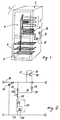
- Figure 1 is a schematic view of a refrigerator provided with the device of the invention
- Figure 2 is a partial schematic view of the electrical circuit of a refrigerator such as that shown in Figure 1.
- a refrigerator 1 for example an upright refrigerator
- a cabinet 2 housing a freezer compartment 3 and a refrigeration compartment 4.
- Hairpin evaporator coils indicated respectively by 6 and 7 are contained in these compartments (which are provided with usual walls and closure doors, not shown). These coils form part of a single evaporator of the refrigeration circuit, which is of known type and therefore not further described.
- a usual defrosting electrical resistance heater 8 which is activated in known manner (for example during predetermined cycles) in such a manner as to (partially or totally) defrost the coil 7 and the walls of the compartment 4.
- the electrical resistance heater 8 is connected to a device 10 which measures the temperature of the environment containing the refrigerator 1, to allow the resistance heater 8 to be powered only when this temperature exceeds 20-22°C.
- the device 10 comprises a temperature sensor member 15 associated with the cabinet 2 and located in such a position as to measure the ambient temperature without being influenced by the internal temperature of the compartment 4.
- This sensor is positioned for example on the outside of said cabinet.
- the sensor is connected to a switch member 16 connected in series with the resistance heater 8.
- the senor is a bimetallic element 17 in the form of a strip connected in series with the resistance heater 8 and located in such a position as to sense ambient temperature.
- the element 17 also acts as a switch because when ambient temperature exceeds 20°C it changes its spatial position to open the electrical power circuit to the resistance heater 8.
- FIG. 2 One embodiment of this circuit is shown in Figure 2. It comprises an electrical feed line 20 of known type and a return line 21, to which there is connected an electrical branch 22 comprising a switch 23 controlled by the usual thermostat positioned in the refrigeration compartment 4. To this branch there is connected a usual motor-compressor unit 25 provided with the necessary starter device 25A and protection device 25B, and forming part of the said refrigeration circuit.
- the bimetallic element 17 is connected in series with the resistance heater 29 to act on fixed contacts 37 and 38 of the branch 28.
- the switching thermostat 23 When the required temperature is reached the switching thermostat 23 opens and interrupts the power passing through it to the motor-compressor unit 25.
- the resistance heater 29 is powered at one end (line 20) via the bimetallic element 17 and at its other end (line 21) via the motor-compressor unit 25 (the resistance of the resistance heater 29 is much higher than the internal resistance of the electric motor, so that during said rest stage the motor windings merely act as the conducting wire to feed the electrical signal from the line 21 to the resistance heater 29).
- the resistance heater 29 heats the compartment 4 and the coil 7, to defrost them.
- the bimetallic element 17 changes its spatial arrangement and separates from the contacts 37, 38. In this manner power is cut off to the resistance heater 29 with the result that defrosting takes place naturally without the operation of said resistance heater.
- the element 17 maintains its position of separation from the contacts 37, 38 until ambient temperature falls a few degrees below the said 20°C (for example to below 16°C).
- the element 17 then again closes said contacts to again power the resistance heater 29.
- the resistance heater 29 is not powered, with consequent energy saving.
- the switching thermostat 23 closes to restore normal operating conditions.
- the described device can obviously be constructed in a more complicated manner, for example by connecting the sensor 15 to an electrical or electronic circuit (for example of microprocessor type) which acts on the switch 16 so that it closes and opens on the basis of the temperature of the environment containing the refrigerator 1.
- an electrical or electronic circuit for example of microprocessor type
Abstract
A device (10) for reducing energy consumption during the defrosting of a refrigerator (1), such as a domestic refrigerator, comprising at least one compartment, such as a refrigeration compartment (4), either in combination or not in combination with a preservation and/or freezing compartment (3), and provided with at least one electrical resistance heater (8) for automatically defrosting the usual evaporator (7) contained in said compartment (4), said refrigerator (1) being located in an environment such as a kitchen, cellar or the like, comprises at least one temperature sensor (15) connected to a switch member (16) connected in series with said electrical resistance heater (8), said sensor (15) being arranged to measure the temperature of the environment housing the refrigerator (1) and to interrupt electrical feed to the resistance heater (8) when ambient temperature exceeds a predetermined value such as to allow at least partial defrosting of the evaporator (7) without the operation of said resistance heater (8).
Description
- This invention relates to a device in accordance with the introduction to the independent claim.
- With particular but non-limiting reference to a domestic refrigerator comprising a freezer compartment and a refrigeration compartment, it is well known that the evaporators contained in said compartments require periodic defrosting.
- This periodic defrosting is particularly required in the refrigeration compartment. This is achieved for example by timed activation of a defrosting resistance heater positioned at the evaporator.
- This need can however be satisfied without activating said resistance heater if the temperature in the environment containing the refrigerator exceeds 20-22°C and the refrigerator compressor is halted. In this case the heat transmitted through the refrigerator walls is sufficient to raise the temperature within the refrigeration compartment to an extent sufficient to defrost its walls (in particular that at the evaporator).
- In such a case, activation of the said defrosting resistance heater is unnecessary, such activation resulting only in additional energy consumption to the detriment of the operating costs of the refrigerator.
- An object of the invention is to provide a device which enables the defrosting resistance heater to be switched out of its usual power circuit when the temperature within the environment in which the refrigerator is located exceeds the predetermined temperature, ie exceeds a predetermined value which enables the refrigeration compartment to be defrosted without the operation of said resistance heater. This results in a corresponding energy saving during refrigerator operation.
- A further object is to provide a device of the aforesaid type which is of reliable use and of simple low-cost construction. These and further objects which will be apparent to the expert of the art are attained by a device in accordance with the characterising part of the independent claim.
- The present invention will be more apparent from the accompanying drawing, which is provided by way of non-limiting example and in which:
Figure 1 is a schematic view of a refrigerator provided with the device of the invention; and
Figure 2 is a partial schematic view of the electrical circuit of a refrigerator such as that shown in Figure 1. - With reference to said figures, a refrigerator 1 (for example an upright refrigerator) comprises a
cabinet 2 housing afreezer compartment 3 and a refrigeration compartment 4. Hairpin evaporator coils indicated respectively by 6 and 7 are contained in these compartments (which are provided with usual walls and closure doors, not shown). These coils form part of a single evaporator of the refrigeration circuit, which is of known type and therefore not further described. - In the refrigeration compartment 4 in a position corresponding with the coil 7 there is provided (inside the compartment on a wall thereof, not shown) a usual defrosting electrical resistance heater 8 which is activated in known manner (for example during predetermined cycles) in such a manner as to (partially or totally) defrost the coil 7 and the walls of the compartment 4. According to the invention the electrical resistance heater 8 is connected to a
device 10 which measures the temperature of the environment containing the refrigerator 1, to allow the resistance heater 8 to be powered only when this temperature exceeds 20-22°C. - In this respect, it has been found that with such an ambient temperature, heat is transmitted into the compartment 4 through the
refrigerator cabinet 2 to such an extent as to cause the temperature in said compartment to rise sufficiently to achieve the said defrosting without the need to activate the resistance heater 8. - Specifically, the
device 10 comprises atemperature sensor member 15 associated with thecabinet 2 and located in such a position as to measure the ambient temperature without being influenced by the internal temperature of the compartment 4. This sensor is positioned for example on the outside of said cabinet. The sensor is connected to aswitch member 16 connected in series with the resistance heater 8. - In its most simple form the sensor is a
bimetallic element 17 in the form of a strip connected in series with the resistance heater 8 and located in such a position as to sense ambient temperature. - The
element 17 also acts as a switch because when ambient temperature exceeds 20°C it changes its spatial position to open the electrical power circuit to the resistance heater 8. - One embodiment of this circuit is shown in Figure 2. It comprises an
electrical feed line 20 of known type and areturn line 21, to which there is connected anelectrical branch 22 comprising aswitch 23 controlled by the usual thermostat positioned in the refrigeration compartment 4. To this branch there is connected a usual motor-compressor unit 25 provided with thenecessary starter device 25A andprotection device 25B, and forming part of the said refrigeration circuit. - In parallel with the
switch 23 there is a secondelectrical branch 28 into which the resistance heater for defrosting the coil 7 associated with the compartment 4 is connected. - The
bimetallic element 17 is connected in series with theresistance heater 29 to act onfixed contacts branch 28. - During normal operation of the refrigerator 1 the
resistance heater 29 is short-circuited by the switchingthermostat 23 with the result that no electrical signal passes through thebranch 28, the motor-compressor unit 25 then being powered via thebranch 22. - When the required temperature is reached the switching
thermostat 23 opens and interrupts the power passing through it to the motor-compressor unit 25. During this rest stage (switchingthermostat 23 open), and if ambient temperature is less than 20°C, theresistance heater 29 is powered at one end (line 20) via thebimetallic element 17 and at its other end (line 21) via the motor-compressor unit 25 (the resistance of theresistance heater 29 is much higher than the internal resistance of the electric motor, so that during said rest stage the motor windings merely act as the conducting wire to feed the electrical signal from theline 21 to the resistance heater 29). - Hence during the rest stage the
resistance heater 29 heats the compartment 4 and the coil 7, to defrost them. - When the temperature of the environment containing the refrigerator exceeds 20°C, the
bimetallic element 17 changes its spatial arrangement and separates from thecontacts resistance heater 29 with the result that defrosting takes place naturally without the operation of said resistance heater. Theelement 17 maintains its position of separation from thecontacts element 17 then again closes said contacts to again power theresistance heater 29. During the time in which ambient temperature is such as to allow "natural" defrosting of the compartment 4, theresistance heater 29 is not powered, with consequent energy saving. - After defrosting, the switching
thermostat 23 closes to restore normal operating conditions. - The described device can obviously be constructed in a more complicated manner, for example by connecting the
sensor 15 to an electrical or electronic circuit (for example of microprocessor type) which acts on theswitch 16 so that it closes and opens on the basis of the temperature of the environment containing the refrigerator 1. - A preferred embodiment of the invention has been described. Other embodiments are however possible (comprising usual electrical members or circuits), which are to be considered as falling within the scope of the present document.
Claims (7)
- A device for reducing energy consumption during the defrosting of a refrigerator, such as a domestic refrigerator, comprising at least one compartment, such as a refrigeration compartment, either in combination or not in combination with a preservation and/or freezing compartment, and provided with at least one electrical resistance heater for automatically defrosting the usual evaporator contained in said compartment, said refrigerator being located in an environment such as a kitchen, cellar or the like, characterised by comprising at least one temperature sensor (15) connected to a switch member (16) connected in series with said electrical resistance heater (8), said sensor (15) being arranged to measure the temperature of the environment housing the refrigerator (1) and to interrupt electrical feed to the resistance heater (8) when ambient temperature exceeds a predetermined value such as to allow at least partial defrosting of the evaporator (7) without the operation of said resistance heater (8).
- A device as claimed in claim 1, characterised in that the temperature sensor (15) is positioned on the outside of the refrigerator cabinet (2).
- A device as claimed in claim 1, characterised in that the temperature sensor and the switch member are a bimetallic element (17) connected in series with the defrosting resistance heater.
- A device as claimed in claim 1, characterised in that the electrical feed to the resistance heater is interrupted when ambient temperature is at least 20°C, feed restoration occurring when ambient temperature is equal to or less than 16°C.
- A device as claimed in claim 1, characterised in that the temperature sensor is associated with at least one switch control unit, advantageously an electrical microprocessor circuit.
- A device as claimed in claim 1, comprising an electrical feed circuit for the usual refrigerator motor-compressor unit (25), which is powered via an electrical branch into which there is connected at least one switch (23) controlled by a corresponding known thermostat located in the relative compartment (4) of the refrigerator (1), said switch (23) being connected in parallel with an electrical branch (28) comprising at least one defrosting electrical resistance heater (29), said electrical branches (22, 28) being interposed between an electrical feed line and a return line, characterised in that in series with the electrical resistance heater (29) there is connected an element (17) sensitive to the temperature of the environment in which the refrigerator is situated, said element being able to assume two different spatial positions on the basis of said temperature, such as to enable said resistance heater (29) to be powered when in only one if said positions.
- A device as claimed in claim 6, characterised in that the element (17) connected in series with the electrical resistance heater (29) is a bimetallic strip.
Applications Claiming Priority (2)
| Application Number | Priority Date | Filing Date | Title |
|---|---|---|---|
| ITMI921087U | 1992-12-22 | ||
| IT001087 IT227082Y1 (en) | 1992-12-22 | 1992-12-22 | DEVICE TO REDUCE ENERGY CONSUMPTION DURING THE DEFROSTING PHASE OF A REFRIGERATOR |
Publications (2)
| Publication Number | Publication Date |
|---|---|
| EP0603576A2 true EP0603576A2 (en) | 1994-06-29 |
| EP0603576A3 EP0603576A3 (en) | 1995-01-18 |
Family
ID=11363220
Family Applications (1)
| Application Number | Title | Priority Date | Filing Date |
|---|---|---|---|
| EP93118974A Withdrawn EP0603576A3 (en) | 1992-12-22 | 1993-11-25 | Device for reducing energy consumption during refrigerator defrosting. |
Country Status (2)
| Country | Link |
|---|---|
| EP (1) | EP0603576A3 (en) |
| IT (1) | IT227082Y1 (en) |
Cited By (1)
| Publication number | Priority date | Publication date | Assignee | Title |
|---|---|---|---|---|
| EP1726895A1 (en) * | 2005-05-27 | 2006-11-29 | Giuseppe Floris | Anti-freeze protection device for chillers |
Citations (4)
| Publication number | Priority date | Publication date | Assignee | Title |
|---|---|---|---|---|
| DE943169C (en) * | 1951-07-13 | 1956-05-17 | Gen Motors Corp | Household refrigerator |
| DE1963336A1 (en) * | 1968-12-26 | 1970-08-27 | Ulgor Sci | System for the automatic defrosting of refrigerators |
| DE2557794A1 (en) * | 1975-12-22 | 1977-06-23 | Licentia Gmbh | Refrigerator automatic defrosting control circuit - has series connected phase cutting economiser with frequency reducing counter for reduced energy consumption |
| FR2347634A1 (en) * | 1976-04-08 | 1977-11-04 | Bosch Siemens Hausgeraete | Dual temp. controlled refrigerator - has defrosting heating element in freezer compartment controlled in dependence on ambient temp. |
-
1992
- 1992-12-22 IT IT001087 patent/IT227082Y1/en active IP Right Grant
-
1993
- 1993-11-25 EP EP93118974A patent/EP0603576A3/en not_active Withdrawn
Patent Citations (4)
| Publication number | Priority date | Publication date | Assignee | Title |
|---|---|---|---|---|
| DE943169C (en) * | 1951-07-13 | 1956-05-17 | Gen Motors Corp | Household refrigerator |
| DE1963336A1 (en) * | 1968-12-26 | 1970-08-27 | Ulgor Sci | System for the automatic defrosting of refrigerators |
| DE2557794A1 (en) * | 1975-12-22 | 1977-06-23 | Licentia Gmbh | Refrigerator automatic defrosting control circuit - has series connected phase cutting economiser with frequency reducing counter for reduced energy consumption |
| FR2347634A1 (en) * | 1976-04-08 | 1977-11-04 | Bosch Siemens Hausgeraete | Dual temp. controlled refrigerator - has defrosting heating element in freezer compartment controlled in dependence on ambient temp. |
Cited By (1)
| Publication number | Priority date | Publication date | Assignee | Title |
|---|---|---|---|---|
| EP1726895A1 (en) * | 2005-05-27 | 2006-11-29 | Giuseppe Floris | Anti-freeze protection device for chillers |
Also Published As
| Publication number | Publication date |
|---|---|
| IT227082Y1 (en) | 1997-09-09 |
| ITMI921087V0 (en) | 1992-12-22 |
| EP0603576A3 (en) | 1995-01-18 |
| ITMI921087U1 (en) | 1994-06-22 |
Similar Documents
| Publication | Publication Date | Title |
|---|---|---|
| US5369962A (en) | Refrigeration system configuration | |
| US4297852A (en) | Refrigerator defrost control with control of time interval between defrost cycles | |
| US4197717A (en) | Household refrigerator including a vacation switch | |
| US4327557A (en) | Adaptive defrost control system | |
| US5493867A (en) | Fuzzy logic adaptive defrost control | |
| US3839878A (en) | Apparatus for controlling refrigerator defrost apparatus | |
| US4056948A (en) | Presettable defrost timer | |
| KR0177503B1 (en) | Combined refrigerator and microwave oven with timed overload protection | |
| US4949548A (en) | Process for controlling the operation of a refrigerating unit | |
| EP1496324B1 (en) | Refrigeration appliance with automatic time-determined defrost | |
| EP0484860B1 (en) | Refrigerating apparatus having a single thermostatic temperature control system | |
| US4358933A (en) | Household refrigerator defrost system | |
| EP0603576A2 (en) | Device for reducing energy consumption during refrigerator defrosting | |
| US3277662A (en) | Refrigeration system defrost control | |
| US3885937A (en) | Ice machine control mechanism | |
| GB1591693A (en) | Refrigerator-freezer | |
| US4178771A (en) | Compressor refrigerator | |
| EP0388726B1 (en) | Refrigerating appliance with single thermostatic temperature control device | |
| EP0250909B1 (en) | Control apparatus for a refrigerating appliance of the automatic defroster type | |
| EP0387680A2 (en) | Refrigerating appliance with thermostatic temperature control arrangement | |
| JPH03233280A (en) | Device for controlling defrosting of freeze refrigerator | |
| CA1141980A (en) | Adaptive defrost control system | |
| KR0152871B1 (en) | Defrosting return freezing operation control circuit of show case | |
| JPS5938698Y2 (en) | Control circuit of auger ice maker | |
| CA1167656A (en) | Household refrigerator defrost system |
Legal Events
| Date | Code | Title | Description |
|---|---|---|---|
| PUAI | Public reference made under article 153(3) epc to a published international application that has entered the european phase |
Free format text: ORIGINAL CODE: 0009012 |
|
| AK | Designated contracting states |
Kind code of ref document: A2 Designated state(s): DE FR GB |
|
| PUAL | Search report despatched |
Free format text: ORIGINAL CODE: 0009013 |
|
| AK | Designated contracting states |
Kind code of ref document: A3 Designated state(s): DE FR GB |
|
| STAA | Information on the status of an ep patent application or granted ep patent |
Free format text: STATUS: THE APPLICATION IS DEEMED TO BE WITHDRAWN |
|
| 18D | Application deemed to be withdrawn |
Effective date: 19950719 |