EP0787902A2 - Rotary pump - Google Patents
Rotary pump Download PDFInfo
- Publication number
- EP0787902A2 EP0787902A2 EP97101559A EP97101559A EP0787902A2 EP 0787902 A2 EP0787902 A2 EP 0787902A2 EP 97101559 A EP97101559 A EP 97101559A EP 97101559 A EP97101559 A EP 97101559A EP 0787902 A2 EP0787902 A2 EP 0787902A2
- Authority
- EP
- European Patent Office
- Prior art keywords
- rotor
- housing
- peri
- curved surface
- chamber
- Prior art date
- Legal status (The legal status is an assumption and is not a legal conclusion. Google has not performed a legal analysis and makes no representation as to the accuracy of the status listed.)
- Withdrawn
Links
- 239000012530 fluid Substances 0.000 claims abstract description 53
- 238000004891 communication Methods 0.000 claims abstract description 50
- 230000006835 compression Effects 0.000 claims abstract description 26
- 238000007906 compression Methods 0.000 claims abstract description 26
- 230000003247 decreasing effect Effects 0.000 claims abstract description 9
- 230000001965 increasing effect Effects 0.000 claims abstract description 8
- 239000000203 mixture Substances 0.000 description 10
- 238000010276 construction Methods 0.000 description 8
- 239000000446 fuel Substances 0.000 description 8
- 239000003921 oil Substances 0.000 description 8
- 238000002485 combustion reaction Methods 0.000 description 6
- 238000004519 manufacturing process Methods 0.000 description 6
- 230000002093 peripheral effect Effects 0.000 description 5
- 239000010687 lubricating oil Substances 0.000 description 4
- 238000003754 machining Methods 0.000 description 4
- 238000005086 pumping Methods 0.000 description 4
- 230000004323 axial length Effects 0.000 description 3
- 208000028659 discharge Diseases 0.000 description 3
- 239000007789 gas Substances 0.000 description 3
- 238000006073 displacement reaction Methods 0.000 description 2
- 238000000034 method Methods 0.000 description 2
- 238000012986 modification Methods 0.000 description 2
- 230000004048 modification Effects 0.000 description 2
- 238000007789 sealing Methods 0.000 description 2
- 241000755266 Kathetostoma giganteum Species 0.000 description 1
- 238000013459 approach Methods 0.000 description 1
- 230000002708 enhancing effect Effects 0.000 description 1
- 239000010720 hydraulic oil Substances 0.000 description 1
- 238000009434 installation Methods 0.000 description 1
- 239000000314 lubricant Substances 0.000 description 1
- 230000001050 lubricating effect Effects 0.000 description 1
- 238000005461 lubrication Methods 0.000 description 1
- 239000007921 spray Substances 0.000 description 1
Images


Classifications
-
- F—MECHANICAL ENGINEERING; LIGHTING; HEATING; WEAPONS; BLASTING
- F04—POSITIVE - DISPLACEMENT MACHINES FOR LIQUIDS; PUMPS FOR LIQUIDS OR ELASTIC FLUIDS
- F04C—ROTARY-PISTON, OR OSCILLATING-PISTON, POSITIVE-DISPLACEMENT MACHINES FOR LIQUIDS; ROTARY-PISTON, OR OSCILLATING-PISTON, POSITIVE-DISPLACEMENT PUMPS
- F04C2/00—Rotary-piston machines or pumps
- F04C2/02—Rotary-piston machines or pumps of arcuate-engagement type, i.e. with circular translatory movement of co-operating members, each member having the same number of teeth or tooth-equivalents
- F04C2/063—Rotary-piston machines or pumps of arcuate-engagement type, i.e. with circular translatory movement of co-operating members, each member having the same number of teeth or tooth-equivalents with coaxially-mounted members having continuously-changing circumferential spacing between them
-
- F—MECHANICAL ENGINEERING; LIGHTING; HEATING; WEAPONS; BLASTING
- F04—POSITIVE - DISPLACEMENT MACHINES FOR LIQUIDS; PUMPS FOR LIQUIDS OR ELASTIC FLUIDS
- F04C—ROTARY-PISTON, OR OSCILLATING-PISTON, POSITIVE-DISPLACEMENT MACHINES FOR LIQUIDS; ROTARY-PISTON, OR OSCILLATING-PISTON, POSITIVE-DISPLACEMENT PUMPS
- F04C2/00—Rotary-piston machines or pumps
- F04C2/22—Rotary-piston machines or pumps of internal-axis type with equidirectional movement of co-operating members at the points of engagement, or with one of the co-operating members being stationary, the inner member having more teeth or tooth-equivalents than the outer member
-
- F—MECHANICAL ENGINEERING; LIGHTING; HEATING; WEAPONS; BLASTING
- F04—POSITIVE - DISPLACEMENT MACHINES FOR LIQUIDS; PUMPS FOR LIQUIDS OR ELASTIC FLUIDS
- F04C—ROTARY-PISTON, OR OSCILLATING-PISTON, POSITIVE-DISPLACEMENT MACHINES FOR LIQUIDS; ROTARY-PISTON, OR OSCILLATING-PISTON, POSITIVE-DISPLACEMENT PUMPS
- F04C2/00—Rotary-piston machines or pumps
- F04C2/02—Rotary-piston machines or pumps of arcuate-engagement type, i.e. with circular translatory movement of co-operating members, each member having the same number of teeth or tooth-equivalents
- F04C2/063—Rotary-piston machines or pumps of arcuate-engagement type, i.e. with circular translatory movement of co-operating members, each member having the same number of teeth or tooth-equivalents with coaxially-mounted members having continuously-changing circumferential spacing between them
- F04C2/067—Rotary-piston machines or pumps of arcuate-engagement type, i.e. with circular translatory movement of co-operating members, each member having the same number of teeth or tooth-equivalents with coaxially-mounted members having continuously-changing circumferential spacing between them having cam-and-follower type drive
Definitions
- the present invention relates to a rotor-type pump suitable for a hydraulic pump which is used to produce the oil pressure required to circulate lubricant to automobile parts such as various moving engine parts or to deliver working fluid to power steering for instance, and specifically to techniques of a rotor-type pump substantially similar to a construction of a Wankel engine employing a rotor with three lobes each of which follows a peri-trochoidal or epi-trochoidal curved surface of a rotor housing in which the rotor turns.
- the external gear-type pump uses a pair of meshing gears.
- the plunger pump uses a plurality of plungers.
- the vane pump uses a plurality of vanes radially slidably set in slots in the pump rotor.
- the internal gear-type pump such as a trochoid pump or a gear-type oil pump with a pair of meshing gears and a crescent between the gears, is often used.
- the Wankel engine typically has a rotor housing, a pair of flat-faced side housings enclosing and sealing the rotor housing, a main shaft or a crankshaft (more accurately an eccentric shaft) with a rotor journal eccentric to the center line of the eccentric shaft (equal to the drive shaft), a substantially tri-angular rotor being rotatable eccentrically in the rotor housing and having three rotor lobes or apexes which are circumferentially equi-distant spaced to each other on the outer periphery of the rotor and follow the epi-trochoidal curve of the inner face of the housing.
- An external gear (stationary gear) member is mounted in one (usually a rear side housing) of the side housings and has the bearing that supports one end of the eccentric shaft, while an internal gear is installed in the rotor.
- the rotor fits on the eccentric rotor journal, and the internal gear (the rotor gear) meshes with the stationary gear of the side housing and is guided by the stationary gear and revolves around the latter.
- the apex seals on the three lobes are in contact with and tightly fit against the inner face of the rotor housing to provide a tight seal, and thus provide three separate chambers between the respective two adjacent rotor lobes. With the internal gear (the rotor) revolving around the stationary gear of the side housing, these chambers increase and decrease in volume.
- an exhaust port is formed in the rotor housing, whereas an intake port is formed in the rotor housing or in the side housing, so that the two ports are arranged parallel to each other in one curved side wall of the rotor housing.
- Also provided in the rotor housing is at least one spark plug (usually a pair of spark plugs are provided such that the plugs face the two ports).
- the gear ratio between the rotor gear and the stationary gear is set at 1 : 3 so that the output shaft (i.e., the eccentric shaft) rotates three times every revolution of the rotor, and so that there are four stages (namely an intake stroke, a compression stroke, a power stroke and an exhaust stroke ) with respect to each of three chambers defined between three rotor lobes, during one revolution of the rotor.
- the Wankel engine operates as follows.
- the space (the volumetric capacity of the chamber) between the one lobe (the leading lobe), the adjacent lobe (the trailing lobe) and the housing begins to increases to produce a partial vacuum and to cause the air-fuel mixture to enter.
- the space between the rotor and housing continues to increase.
- the air-fuel mixture is sealed between the leading and trailing lobes, and then the mixture is compressed.
- Wankel engine the complete series of actions take place between three pairs of rotor lobes. Three sets of actions which occur at the same time in the engine, provide a high engine performance.
- Wankel engine the fuel system mixes a fine spray of fuel (gasoline) with air to make a combustible and compressible air-fuel mixture and the compressible mixture is compressed on compression stroke and ignited and expanded on power stroke, whereas the oil pump is used to produce an increased pressure of incompressible working fluid.
- the Wankel engine is applied to a compressible fluid (air-fuel mixture) and so designed to function as an internal combustion engine by way of compressing and expanding action of compressible air-fuel mixture (i.e., changes in volume in the combustion chamber).
- oil pumps must be applied to incompressible fluid such as lubricating oil for automotive moving or rotating parts or working fluid for a power steering device.
- one meshing pair (the stationary gear and the rotor gear) are provided to control the rotation of the rotor in such a proper manner that the rotor satisfactorily follows the epi-trochoidal curve of the inner face of the rotor housing and rotates eccentrically around the stationary gear.
- the stationary gear is mounted in the side housing, whereas the rotor gear is installed in the rotor, and thus such a guiding device composed of the stationary gear (external gear) and the rotor gear (internal gear) requires a high machining accuracy of the meshing pair.
- a conventional guiding device has a complicated structure and is generally constructed by many parts. If the conventional guiding device is applied to a rotor-type pump, the high accuracy of machining of the meshing gears and the complicated structure of the guiding device increase production costs of the rotor-type pump which utilizes a basic construction of the Wankel engine. Additionally, the stationary gear and the rotor gear meshing each other have required a comparatively great installing space in the housing, and thus there is a tendency that the entire size and weight of the rotor-type pump increase.
- the present invention relates to techniques for optimally applying the basic construction of the Wankel engine to hydraulic pumps which use incompressible fluid. It is, therefore, an object of the present invention to provide a rotor-type pump which can provide a superior pumping action, permitting changes in the volumetric capacity of the working chambers between rotor lobes.
- a rotor-type pump comprises a drive shaft, a housing defining therein an internal space and having a circumferentially-extending peri-trochoidal curved surface in an outer periphery of the housing, an eccentric rotor journal fixedly connected to the drive shaft for co-rotation, an axis of the eccentric rotor journal being eccentric to a center line of the drive shaft, a rotor slidably fitted to the eccentric rotor journal and having circumferentially equi-distant spaced plural lobes on an outer periphery of the rotor so that the rotor rotates eccentrically in the housing, keeping the plural lobes in sliding-contact with the peri-trochoidal curved surface, plural working-fluid chambers defined between respective two adjacent lobes of the plural lobes by the peri-trochoidal curved surface and the outer periphery of the rotor, the plural working-fluid chambers
- a rotor-type pump comprises a drive shaft, a rotor housing having a recessed portion therein, the recessed portion being defined by a circumferentially-extending peri-trochoidal curved surface and a radially-extending flat-faced surface, and the peri-trochoidal curved surface being formed with two diametrically-opposing raised portions being point-symmetrical with respect to a center line of the drive shaft, a side cover hermetically covering an opening end of the rotor housing in a fluid-tight fashion, an eccentric rotor journal fixedly connected to the drive shaft for co-rotation, an axis of the eccentric rotor journal being eccentric to a center line of the drive shaft, a rotor slidably fitted to the eccentric rotor journal and having circumferentially equi-distant spaced three lobes on an outer periphery of the rotor so that the rotor rotates eccentrically in the housing, keeping the three lobes
- the communication passage may comprise a substantially C-shaped fluid communication passage having two ports which expose through the peri-trochoidal curved surface to the recessed portion and respectively oppose the intake port and the discharge port, the two ports being opened and closed by the outer periphery of the rotor. More preferably, the communication passage may comprise a fluid-communication recessed hole formed in the radially-extending flat-faced surface of the recessed portion of the rotor housing, the fluid-communication recessed hole being opened and closed by a flat-faced side wall of the rotor. Alternatively, the communication passage may comprise a fluid-communication recessed hole formed in a flat-faced surface of the side cover facing the flat-faced surface of the recessed portion of the rotor housing.
- the rotor-type pump may further comprise a rotor guiding means including an endless guide groove formed in the side cover and contoured along the peri-trochoidal curved surface and three guide pins each tightly press-fitted into an axial bore formed in the rotor near the associated lobe and loosely fitted into the endless guide groove.
- a rotor guiding means including an endless guide groove formed in the side cover and contoured along the peri-trochoidal curved surface and three guide pins each tightly press-fitted into an axial bore formed in the rotor near the associated lobe and loosely fitted into the endless guide groove.
- Fig. 1 is a longitudinal cross-sectional view illustrating a first embodiment of a rotor-type pump made according to the invention.
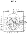
- Fig. 2 is a lateral cross-sectional view taken along the line A - A of Fig. 1.
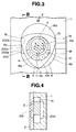
- Fig. 3 is a lateral cross-sectional view illustrating a second embodiment of a rotor-type pump of the invention.
- Fig. 4 is a partial cross-sectional view taken along the line B - B of Fig. 3.
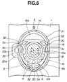
- Fig. 5 is a longitudinal cross-sectional view illustrating a rotor-type pump of a third embodiment with a improved rotor guiding device.
- Fig. 6 is a lateral cross-sectional view taken along the line C - C of Fig. 4.
- the rotor-type pump includes a rotor housing 1 firmly secured to the stationary engine part such as a cylinder block, a side cover 2 (corresponding to a side housing) firmly secured to the rear flat-faced end of the housing in such a manner as to hermetically cover the rear opening end of the housing 1 in a fluid-tight fashion, the drive shaft 4 which penetrates the circular center bore 1a of the housing and the circular center bore 2a of the cover 2, and a substantially tri-angular rotor 5 rotatably enclosed in the recessed portion 1b (or the internal space) of the housing 1.
- the rotor housing 1 and the side cover 2 constructs a pump housing assembly.
- the recessed portion 1b of the housing 1 is comprised of a circumferentially-extending endless-belt like curved surface 6 and a radially-extending flat-faced surface.
- the circumferentially-extending curved surface 6 of the recessed portion 1b of the housing is shaped as a peri-trochoidal or epi-trochoidal curved surface 6.
- the housing is formed integral with an essentially cylindrical oil seal housing 7 extending frontwardly from the housing side wall facing the side cover 2.
- the cover 2 is substantially rectangular in shape in the same manner as the contour of the rear flat-faced end of the cover 2.
- Reference sign 9 denotes a stationary gear assembly composed of a cylindrical gear-mounting base 9a (simply a base) and an external toothed portion 9b.
- the base 9a is tightly press-fitted to the inner periphery of the center bore 2a of the side cover 2.
- the external toothed portion 9b is tightly press-fitted to the outer periphery of the left-hand half of the base 9a and thus the gear assembly 9 is stationary with respect to the side cover 2.
- the drive shaft 4 is directly connected to the crankshaft (not shown) of the internal combustion engine.
- An eccentric collar 10 is fixedly connected to the outer periphery of the drive shaft 4 by way of a key 11 tightly fitted into an elongated, axially-extending key way formed at the outer periphery of the drive shaft.
- a drive pulley (a timing-belt pulley) 12 is firmly secured to the relatively small-diameter front end 4a of the shaft 4 by means of a bolt 13.
- Reference sign 14 denotes a sprocket fixed onto the outer periphery of the relatively small-diameter portion of the drive shaft 4 so that the right-hand flat-faced side wall of the sprocket 14 abuts the stepped end portion (or the annular radially-extending flat face) 4b of the shaft 4.
- the pulley 12 is formed integral with an axially backwardly extending cylindrical boss-like portion 12a being fitted onto the outer periphery of the front end 4a of the drive shaft. Therefore, the rotational force or driving torque is transmitted from the pulley 12 to the drive shaft 4 through a timing belt (not shown). Also, a sealing member 15 such as an oil seal is provided in an essentially cylindrical seal mounting bore of the seal housing 7 to provide a tight seal between the outer periphery of the boss-like portion 12a and the inner periphery of the seal mounting bore of the seal housing 7.
- the previously-noted eccentric collar 10 consists of a cylindrical portion 10a which is fitted to the outer periphery of the drive shaft 4 and fixedly connected to the shaft 4 by way of the key and key way, and an eccentric rotor journal portion 10b which is formed integral with the cylindrical portion 10a.
- the central axis P of the eccentric rotor journal portion 10b is radially eccentric to the central axis X of the drive shaft 4 by a predetermined distance e .
- the left-hand end of the cylindrical portion 10a is fitted into the center bore 1a of the housing 1 whereas its right-hand end penetrates the center bore 2a of the cover 2.
- the eccentric rotor journal 10b is formed with a plurality of lightening holes H for the purpose of weight balance as well as lightening.
- the axial length (or the thickness) of the rotor is designed to be slightly smaller than the axial length of the recessed portion 1b of the housing 1.
- the rotor has three lobes 5a, 5b and 5c. Defined is the working-fluid chamber between the outer peripheral curved surface over the two adjacent lobes and the peri-trochoidal curved surface 6 of the recessed portion 1b. Thus, three working-fluid chambers 16a, 16b and 16c are defined between the outer periphery of the rotor 5 and the inner peripheral face of the rotor housing 1. In the rotor-type pump, the three working-fluid chambers themselves rotate in synchronization with rotation of the rotor 5, as will be more fully discussed later.
- the rotor rotates eccentrically around the stationary gear assembly 9 and also follows a specified orbit that permanently keeps all of the three rotor lobes 5a, 5b and 5c in sliding-contact with the peri-trochoidal curved surface 6 of the housing 1.
- the rotor 5 is formed with the central stepped bore composed of a comparatively small-diameter bore 5d and a comparatively large-diameter bore 5e.
- the inner periphery of the small-diameter bore 5d of the rotor is fitted to and rotatably supported on the outer periphery of the eccentric rotor journal 10b of the eccentric collar.
- the large-diameter bore 5e of the rotor is formed, on its inner periphery, with an internal toothed portion 17 (corresponding to a rotor gear) being partly meshable with the external toothed portion 9b of the stationary gear 9.
- the housing 1 are formed, at the right-hand side (viewing Fig. 2), with essentially parallel two ports, namely an intake port 18 (lowerport) and a discharge port (upper port) 19.
- the respective ports 18 and 19 communicate the recessed portion 1b of the housing 1.
- a substantially C-shaped fluid communication passage 20 is formed in the left-hand side of the housing 1. As seen in Fig.
- the lobe 5b corresponds to the leading lobe and the lobe 5a corresponds to the trailing lobe.
- the working fluid in the chamber 16a is in the compressed state. Assuming that under the condition shown in Fig. 2 the rotor has farther turned approximately 30 degrees and thus the leading rotor lobe 5b has advanced approximately 30 degrees, the fluid in the chamber 16a reaches the maximum compressed state.
- the intake port 18 is formed in the housing 1 near the right-hand central raised portion 6b of the peri-trochoidal curved surface 6 which raised portion 6b is somewhat higher level than the intake port 18, whereas the exhaust port 19 is formed in the housing 1 near the right-hand raised portion 6b somewhat lower than the discharge port 19.
- the right-hand raised portion 6b and the left-hand raised portion 6a are diametrically opposed to each other and point-symmetrical with respect to the central axis X of the drive shaft 4.
- First and second ports 20a and 20b of the communication passage 20 horizontally expose through the peri-trochoidal curved surface 6 to one or two chambers in a manner so as to oppose the respective ports 18 and 19.
- Fig. 2 shows a condition in which the first rotor lobe 5a just passes through the lowermost position of the peri-trochoidal curved surface 6.
- another rotor lobe begins to clear the first port 20a in a manner so as to permit the fluid communication between the working-fluid chamber between the one lobe (e.g., the second lobe 5b) and the other lobe (e.g., the first lobe 5a corresponding to the trailing lobe if the second lobe 5b is the leading lobe) via the communication passage 20, whereas another rotor lobe (e.g., the third lobe 5c) has cleared the intake port 18 in a manner so as to block the fluid communication between the intake port 18 and the chamber between the above-mentioned other two lobes (i.e., the lobes 5a and 5c).
- another rotor lobe e.g., the third lobe 5c
- the total volumetric capacity of the communication passage 20 is set at a predetermined volumetric capacity which is obtained by subtracting a predetermined volumetric capacity essentially corresponding to the minimum volumetric capacity (identical to the volumetric capacity of the lower-left working-fluid chamber when one of the three lobes reaches the lowermost position of the peri-trochoidal curved surface 6 and also another lobe begins to close the second port 20b of the communication passage) from the maximum volumetric capacity (identical to the volumetric capacity of the lower working-fluid chamber when one of the three lobes reaches the uppermost position of the peri-trochidal curved surface 6 or to the volumetric capacity of the upper working-fluid chamber when one of the three lobes reaches the lowermost position of the peri-trochidal curved surface 6).
- the total volumetric capacity of the communication passage 20 is set at a value slightly greater than the previously-noted predetermined volumetric capacity.
- the intake stage (see the chamber 16c of Fig. 2) of the rotor-type pump of the embodiment is similar to the intake stroke of the typical Wankel engine, and also the discharge stage (in Fig. 2 the the chamber 16b begins to the discharge stage) of the pump of the embodiment is similar to the exhaust stroke of the Wankel engine. Note that the compression and expansion stages of the exemplified pump are considerably different from those of the Wankel engine.
- the chamber e.g., the lower-left chamber 16a
- the chamber e.g., the upper-left or upper chamber 16b
- the stage is expansion
- the communication passage 20 for a predetermined time duration from the time when the leading lobe has cleared the first port 20a to the time when the leading lobe has cleared the second port 20b, so as to permit changes in the volumetric capacity of the two adjacent chambers whose stages are compression and expansion strokes.
- the eccentric collar 10 rotates together with the drive shaft 4 when the drive shaft 4 is rotated by way of the drive pulley 12, and thus the rotational force (torque) is transmitted through the outer peripheral surface of the eccentric rotor journal portion 10b to the rotor 5.
- the meshing-gear type rotor guiding device namely the stationary gear 9 and the rotor gear 17
- the rotor rotates eccentrically around the stationary gear 9, following a specified orbit that permanently keeps all of the rotor lobes 5a through 5c in sliding-contact with the peri-trochoidal curved surface 6 of the recessed portion 1b of the rotor housing.
- the volumetric capacity of the chamber begins to decrease and simultaneously a first chamber 16a (decreasing in volume) is communicated, via the communication passage 20 with the first port 20 opened, with a second chamber 16b (increasing in volume and lying near the leading lobe associated with the first chamber).
- the rotor curved peripheral surface extending between the leading and trailing lobes (5b and 5a) serves as a pressure surface which thrusts out or pushes out the working fluid (or lubricating oil) from the first chamber (decreasing in volume and being subjected to the compression stroke) to the second chamber (increasing in volume and being subjected to the expansion stroke) by virtue of the communication passage 20.
- the stage of the chamber 16a of Fig. 2 is the middle stage of the compression operation. In the middle stage of the compression, for example the lobe 5b begins to close the second port 20b. Then, the stage shifts from the last stage of the compression to the expansion stage. Once more again, note that the chamber being subjected to the expansion stage cooperates with the chamber being subjected to the compression stage.
- the stage of the chamber 16b of Fig. 2 is the last stage of the expansion operation.
- the total volumetric capacity of all working-fluid chambers in the rotor-type pump is greater than that of the internal gear-type pump and thus the displacement per one revolution of the rotor is relatively great.
- the rotor-type pump is superior to the typical internal gear-type pump. If the same displacement is required, the rotor-type pump can be designed to be smaller than the internal gear-type pump, and thus the total weight of the pumping system can be decreased.
- Figs. 3 and 4 there is shown the rotor-type pump of the second embodiment.
- the construction of the rotor-type pump of the second embodiment is similar to that of the first embodiment, and thus the same reference signs used to designate elements in the rotor-type pump of the first embodiment as shown in Figs. 1 and 2 will be applied to the corresponding elements used in the second embodiment, for the purpose of comparison of the first and second embodiments.
- the second embodiment is slightly different from the first embodiment in that in case of the first embodiment the communication passage 20 required for the compression and expansion operations is formed in the left-hand side of the rotor housing 1 such that its two ports 20a and 20b respectively oppose the intake and discharge ports 18 and 19 and formed in the peri-trochoidal curved surface 6 of a comparatively narrow axial length, whereas in case of the second embodiment a communication passage 200 required for the compression and expansion operations is formed in a comparatively wide radially-extending flat-faced portion of the recessed portion 1b of the rotor housing 1 as a fluid-communication recessed hole (200a, 200b, 200c) so that the recessed hole faces the flat-faced side wall of the rotor 5.
- the ports 20a and 20b are opened and closed by way of the lobes (5a, 5b, 5c) on the rotor curved peripheral surface.
- the upper rounded portion 200b of the vertically-extending elongated I-shaped communication passage 200 and the lower rounded portion 200a of the communication passage 200 are opened and closed by way of one flat-faced side wall of the rotor 5. That is, the lower and upper rounded portions 200a and 200b of the communication passage 200 correspond to the respective ports 20a and 20b, and the relatively narrow medium portion 200c serves to intercommunicate the upper and lower rounded portions 200a and 200b.
- the I-shaped, recessed communication passage 200 of the second embodiment is so designed to be symmetrical with respect to the horizontal line passing through the two points, namely the central axis of the drive shaft 4 and the left-hand raised portion 6a of he peri-trochoidal curved surface 6.
- the machining of the I-shaped, recessed communication passage 200 is easier than that of the C-shaped communication passage 20.
- the manufacturing efficiency can be further enhanced, thus reducing production costs.
- the modification of the I-shaped, recessed communication passage is indicated by the phantom line.
- the modified communication passage 201 is formed in the side cover 2 but not in the rotor housing 1.
- the construction of the rotor-type pump of the third embodiment is almost similar to that of the first embodiment and thus the same reference signs used to designate elements in the first embodiment will be applied to the corresponding elements used in the third embodiment, for the purpose of comparison of the first and third embodiments.
- the rotor guiding device composed of the stationary gear assembly 9 tightly fitted to the rear side cover 2 and the rotor gear 17 installed on the inner periphery of the rotor 5 controls the rotation of the rotor by way of partial meshed-engagement between the stationary gear and the rotor gear.
- the improved rotor guiding device of the third embodiment utilizes the cam connection between an endless guide groove 31 which is formed in the side cover 2 in such a manner as to be precisely contoured along the peri-trochoid curve of the curved surface 6 and three guide pins 30 which are fitted to the rotor 5 near the three lobes 5a through 5c.
- the peri-trochoidal curved guide groove 31 is formed into a rectangular shape in cross-section by a bottom surface and two opposing side walls and defined in the inside wall of the side cover 2.
- Each of the three guide pins 30 is a parallel pin with two flat ends.
- guide pins 30 are tightly press-fitted to the respective guide-pin holes (or cylindrical axial bores) 32 formed in the rotor near the three lobes 5a, 5b and 5c.
- the guide-pin end 30a (corresponding to a portion of the guide pin 30 projected from the flat-faced surface of the rotor 5) is loosely fitted into the guide groove 31 to permit a smooth eccentric rotation of the rotor.
- the three guide-pin holes 32 are axially bored in the rotor near the three rotor lobes so that the center axis of each guide-pin hole 32 is located on the line segment between the associated apex of the rotor and the central axis P of the eccentric rotor journal 10b and the three guide-pin holes 32 match the peri-trochoidal curved guide groove.
- the three guide pins 30 smoothly slide along the peri-trochoidal curved guide groove 31, and whereby he rotor 5 can smoothly and eccentrically rotate, following an orbit that keeps all of the three lobes 5a, 5b and 5c in sliding-contact with the peri-trochoidal curved surface 6.
- the rotor-type pump of the third embodiment uses a simplified rotor guiding device comprising a peri-trohoidal curved guide groove 31 and three guide pins 30 in cam-connection with the guide groove 31, instead of a conventional complicated rotor guiding device comprising a stationary gear attached to a rotor side cover (or a rotor side housing) and an internal rotor gear in meshed-engagement with the stationary gear.
- a simplified rotor guiding device comprising a peri-trohoidal curved guide groove 31 and three guide pins 30 in cam-connection with the guide groove 31, instead of a conventional complicated rotor guiding device comprising a stationary gear attached to a rotor side cover (or a rotor side housing) and an internal rotor gear in meshed-engagement with the stationary gear.
- the installation space for the simplified rotor guiding device (having the guide pins 30 and the guide groove 3) is smaller than the prior art rotor guiding device (having the stationary gear and the rotor gear), and thus the rotor-type pump can be small-sized.
- the guide groove 31 is formed in the side cover 2.
- the guide groove may be formed in the radially-extending flat-faced portion of the rotor housing and the three guide pins may be projected frontwardly for loose fit between the guide pins and the guide groove.
- the rotor-type pump of the invention may be applied to all kinds of incompressible fluid as well as hydraulic oil.
Landscapes
- Engineering & Computer Science (AREA)
- Mechanical Engineering (AREA)
- General Engineering & Computer Science (AREA)
- Rotary Pumps (AREA)
- Details And Applications Of Rotary Liquid Pumps (AREA)
Abstract
Description
- The present invention relates to a rotor-type pump suitable for a hydraulic pump which is used to produce the oil pressure required to circulate lubricant to automobile parts such as various moving engine parts or to deliver working fluid to power steering for instance, and specifically to techniques of a rotor-type pump substantially similar to a construction of a Wankel engine employing a rotor with three lobes each of which follows a peri-trochoidal or epi-trochoidal curved surface of a rotor housing in which the rotor turns.
- As is generally known, there are several general types of oil pumps used in pressure-feed systems, for lubrication of an internal combustion engine or for delivery of working fluid to a power steering system which serves to produce a steering assistance. In one, the external gear-type pump uses a pair of meshing gears. In another, the plunger pump uses a plurality of plungers. In another, the vane pump uses a plurality of vanes radially slidably set in slots in the pump rotor. Also, the internal gear-type pump such as a trochoid pump or a gear-type oil pump with a pair of meshing gears and a crescent between the gears, is often used. To provide a higher-performance pump, it is desired to apply a basic construction of the Wankel engine (often called a four-stroke cycle rotary-combustion engine) to hydraulic pumps Hereinafter described briefly is the construction and operation of typical Wankel engines. The Wankel engine typically has a rotor housing, a pair of flat-faced side housings enclosing and sealing the rotor housing, a main shaft or a crankshaft (more accurately an eccentric shaft) with a rotor journal eccentric to the center line of the eccentric shaft (equal to the drive shaft), a substantially tri-angular rotor being rotatable eccentrically in the rotor housing and having three rotor lobes or apexes which are circumferentially equi-distant spaced to each other on the outer periphery of the rotor and follow the epi-trochoidal curve of the inner face of the housing. An external gear (stationary gear) member is mounted in one (usually a rear side housing) of the side housings and has the bearing that supports one end of the eccentric shaft, while an internal gear is installed in the rotor. The rotor fits on the eccentric rotor journal, and the internal gear (the rotor gear) meshes with the stationary gear of the side housing and is guided by the stationary gear and revolves around the latter. The apex seals on the three lobes are in contact with and tightly fit against the inner face of the rotor housing to provide a tight seal, and thus provide three separate chambers between the respective two adjacent rotor lobes. With the internal gear (the rotor) revolving around the stationary gear of the side housing, these chambers increase and decrease in volume. This action is similar to the decrease and increase in volume in the cylinder of a reciprocating engine, as the piston moves up and down. Ordinarily, an exhaust port is formed in the rotor housing, whereas an intake port is formed in the rotor housing or in the side housing, so that the two ports are arranged parallel to each other in one curved side wall of the rotor housing. Also provided in the rotor housing is at least one spark plug (usually a pair of spark plugs are provided such that the plugs face the two ports). In case of a well-known one-rotor Wankel engine, the gear ratio between the rotor gear and the stationary gear is set at 1 : 3 so that the output shaft (i.e., the eccentric shaft) rotates three times every revolution of the rotor, and so that there are four stages (namely an intake stroke, a compression stroke, a power stroke and an exhaust stroke ) with respect to each of three chambers defined between three rotor lobes, during one revolution of the rotor. In detail, the Wankel engine operates as follows. With rotation of the rotor after one of the rotor lobes has cleared the intake port, the space (the volumetric capacity of the chamber) between the one lobe (the leading lobe), the adjacent lobe (the trailing lobe) and the housing begins to increases to produce a partial vacuum and to cause the air-fuel mixture to enter. With a further rotation of the rotor, the space between the rotor and housing continues to increase. When the rotor reaches the point wherein the trailing lobe passes the intake port, the air-fuel mixture is sealed between the leading and trailing lobes, and then the mixture is compressed. When the mixture is nearing the maximum compression at the last stage of the compression (near TDC on the compression stroke), the spark plugs fire to ignite the mixture and thus the combustion takes place. At this stage, the hot burnt gases push the rotor to turn it further around. Thereafter, the hot gases continues to expand and the expand stroke continues until the leading lobe has cleared the exhaust port. The hot burnt gases begin to exhaust from the space between these adjacent lobes via the exhaust port and the exhaust stroke continues. Then the leading lobe has cleared the intake port again. In this manner, the four stages (complete series of actions) are repeatedly executed every revolution of the rotor. Such a conventional Wankel engine has been disclosed in Japanese Utility Model Provisional Publication No. 64-15726. As set forth above, in the Wankel engine, the complete series of actions take place between three pairs of rotor lobes. Three sets of actions which occur at the same time in the engine, provide a high engine performance. However, it is very difficult to apply the basic construction of the Wankel engine as previously noted to oil pumps used in pressure-feed lubricating systems of automotive engines, for the reasons set out below. In Wankel engine the fuel system mixes a fine spray of fuel (gasoline) with air to make a combustible and compressible air-fuel mixture and the compressible mixture is compressed on compression stroke and ignited and expanded on power stroke, whereas the oil pump is used to produce an increased pressure of incompressible working fluid. That is, the Wankel engine is applied to a compressible fluid (air-fuel mixture) and so designed to function as an internal combustion engine by way of compressing and expanding action of compressible air-fuel mixture (i.e., changes in volume in the combustion chamber). On the other hand, oil pumps must be applied to incompressible fluid such as lubricating oil for automotive moving or rotating parts or working fluid for a power steering device. Also, in the typical Wankel engines, one meshing pair (the stationary gear and the rotor gear) are provided to control the rotation of the rotor in such a proper manner that the rotor satisfactorily follows the epi-trochoidal curve of the inner face of the rotor housing and rotates eccentrically around the stationary gear. Generally, the stationary gear is mounted in the side housing, whereas the rotor gear is installed in the rotor, and thus such a guiding device composed of the stationary gear (external gear) and the rotor gear (internal gear) requires a high machining accuracy of the meshing pair. Also, such a conventional guiding device has a complicated structure and is generally constructed by many parts. If the conventional guiding device is applied to a rotor-type pump, the high accuracy of machining of the meshing gears and the complicated structure of the guiding device increase production costs of the rotor-type pump which utilizes a basic construction of the Wankel engine. Additionally, the stationary gear and the rotor gear meshing each other have required a comparatively great installing space in the housing, and thus there is a tendency that the entire size and weight of the rotor-type pump increase.
- The present invention relates to techniques for optimally applying the basic construction of the Wankel engine to hydraulic pumps which use incompressible fluid. It is, therefore, an object of the present invention to provide a rotor-type pump which can provide a superior pumping action, permitting changes in the volumetric capacity of the working chambers between rotor lobes.
- It is another object of the invention to provide a rotor-type pump with a simple rotor guiding device, as compared with a typical Wankel-engine rotor guiding device being comprised of a stationary gear mounted in the side housing and a rotor gear installed in the rotor.
- In order to accomplish the aforementioned and other objects of the present invention, a rotor-type pump comprises a drive shaft, a housing defining therein an internal space and having a circumferentially-extending peri-trochoidal curved surface in an outer periphery of the housing, an eccentric rotor journal fixedly connected to the drive shaft for co-rotation, an axis of the eccentric rotor journal being eccentric to a center line of the drive shaft, a rotor slidably fitted to the eccentric rotor journal and having circumferentially equi-distant spaced plural lobes on an outer periphery of the rotor so that the rotor rotates eccentrically in the housing, keeping the plural lobes in sliding-contact with the peri-trochoidal curved surface, plural working-fluid chambers defined between respective two adjacent lobes of the plural lobes by the peri-trochoidal curved surface and the outer periphery of the rotor, the plural working-fluid chambers rotating in synchronization with rotation of the rotor, an intake port communicating the internal space of the housing, a discharge port communicating the internal space of the housing, and communication means for intercommunicating a first chamber of the plural working-fluid chambers, the first chamber decreasing in volume during compression stage, and a second chamber of the plural working-fluid chambers, the second chamber increasing in volume during expansion stage.
- According to another aspect of the invention, a rotor-type pump comprises a drive shaft, a rotor housing having a recessed portion therein, the recessed portion being defined by a circumferentially-extending peri-trochoidal curved surface and a radially-extending flat-faced surface, and the peri-trochoidal curved surface being formed with two diametrically-opposing raised portions being point-symmetrical with respect to a center line of the drive shaft, a side cover hermetically covering an opening end of the rotor housing in a fluid-tight fashion, an eccentric rotor journal fixedly connected to the drive shaft for co-rotation, an axis of the eccentric rotor journal being eccentric to a center line of the drive shaft, a rotor slidably fitted to the eccentric rotor journal and having circumferentially equi-distant spaced three lobes on an outer periphery of the rotor so that the rotor rotates eccentrically in the housing, keeping the three lobes in sliding-contact with the peri-trochoidal curved surface, three working-fluid chambers defined between respective two adjacent lobes of the three lobes by the peri-trochoidal curved surface and the outer periphery of the rotor, the three working-fluid chambers rotating in synchronization with rotation of the rotor, an intake port communicating the internal space of the housing, a discharge port communicating the internal space of the housing, the intake port and the discharge port being provided parallel to each other, at both sides of a first raised portion of the two diametrically-opposing raised portions, and communication means for intercommunicating a first chamber of the three working-fluid chambers, the first chamber decreasing in volume during compression stage, and a second chamber of the three working-fluid chambers, the second chamber increasing in volume during expansion stage, wherein the communication means including a communication passage formed near a second raised portion of the two diametrically-opposing raised portions. The communication passage may comprise a substantially C-shaped fluid communication passage having two ports which expose through the peri-trochoidal curved surface to the recessed portion and respectively oppose the intake port and the discharge port, the two ports being opened and closed by the outer periphery of the rotor. More preferably, the communication passage may comprise a fluid-communication recessed hole formed in the radially-extending flat-faced surface of the recessed portion of the rotor housing, the fluid-communication recessed hole being opened and closed by a flat-faced side wall of the rotor. Alternatively, the communication passage may comprise a fluid-communication recessed hole formed in a flat-faced surface of the side cover facing the flat-faced surface of the recessed portion of the rotor housing. The rotor-type pump may further comprise a rotor guiding means including an endless guide groove formed in the side cover and contoured along the peri-trochoidal curved surface and three guide pins each tightly press-fitted into an axial bore formed in the rotor near the associated lobe and loosely fitted into the endless guide groove.
- Fig. 1 is a longitudinal cross-sectional view illustrating a first embodiment of a rotor-type pump made according to the invention.
- Fig. 2 is a lateral cross-sectional view taken along the line A - A of Fig. 1.
- Fig. 3 is a lateral cross-sectional view illustrating a second embodiment of a rotor-type pump of the invention.
- Fig. 4 is a partial cross-sectional view taken along the line B - B of Fig. 3.
- Fig. 5 is a longitudinal cross-sectional view illustrating a rotor-type pump of a third embodiment with a improved rotor guiding device.
- Fig. 6 is a lateral cross-sectional view taken along the line C - C of Fig. 4.
- Referring now to the drawings, particularly to Figs. 1 and 2, there is shown the front section of a pump shaft (or a drive shaft) 4 of a rotor-type pump of the first embodiment. The rotor-type pump includes a rotor housing 1 firmly secured to the stationary engine part such as a cylinder block, a side cover 2 (corresponding to a side housing) firmly secured to the rear flat-faced end of the housing in such a manner as to hermetically cover the rear opening end of the housing 1 in a fluid-tight fashion, the
drive shaft 4 which penetrates the circular center bore 1a of the housing and thecircular center bore 2a of thecover 2, and a substantially tri-angularrotor 5 rotatably enclosed in the recessed portion 1b (or the internal space) of the housing 1. The rotor housing 1 and the side cover 2 constructs a pump housing assembly. The recessed portion 1b of the housing 1 is comprised of a circumferentially-extending endless-belt likecurved surface 6 and a radially-extending flat-faced surface. The circumferentially-extendingcurved surface 6 of the recessed portion 1b of the housing is shaped as a peri-trochoidal or epi-trochoidalcurved surface 6. The housing is formed integral with an essentially cylindricaloil seal housing 7 extending frontwardly from the housing side wall facing theside cover 2. Thecover 2 is substantially rectangular in shape in the same manner as the contour of the rear flat-faced end of thecover 2. Thecover 2 is positioned in place by means of apositioning pin 8 and firmly secured to the rear flat-faced end of the housing 1 by way of bolts such as flat-head bolts 3. Reference sign 9 denotes a stationary gear assembly composed of a cylindrical gear-mountingbase 9a (simply a base) and an externaltoothed portion 9b. As clearly seen in Fig. 1, thebase 9a is tightly press-fitted to the inner periphery of the center bore 2a of theside cover 2. The externaltoothed portion 9b is tightly press-fitted to the outer periphery of the left-hand half of thebase 9a and thus the gear assembly 9 is stationary with respect to theside cover 2. Thedrive shaft 4 is directly connected to the crankshaft (not shown) of the internal combustion engine. Aneccentric collar 10 is fixedly connected to the outer periphery of thedrive shaft 4 by way of a key 11 tightly fitted into an elongated, axially-extending key way formed at the outer periphery of the drive shaft. A drive pulley (a timing-belt pulley) 12 is firmly secured to the relatively small-diameter front end 4a of theshaft 4 by means of abolt 13.Reference sign 14 denotes a sprocket fixed onto the outer periphery of the relatively small-diameter portion of thedrive shaft 4 so that the right-hand flat-faced side wall of thesprocket 14 abuts the stepped end portion (or the annular radially-extending flat face) 4b of theshaft 4. Thepulley 12 is formed integral with an axially backwardly extending cylindrical boss-like portion 12a being fitted onto the outer periphery of the front end 4a of the drive shaft. Therefore, the rotational force or driving torque is transmitted from thepulley 12 to thedrive shaft 4 through a timing belt (not shown). Also, a sealingmember 15 such as an oil seal is provided in an essentially cylindrical seal mounting bore of theseal housing 7 to provide a tight seal between the outer periphery of the boss-like portion 12a and the inner periphery of the seal mounting bore of theseal housing 7. The previously-notedeccentric collar 10 consists of acylindrical portion 10a which is fitted to the outer periphery of thedrive shaft 4 and fixedly connected to theshaft 4 by way of the key and key way, and an eccentricrotor journal portion 10b which is formed integral with thecylindrical portion 10a. As best in Fig. 2, the central axis P of the eccentricrotor journal portion 10b is radially eccentric to the central axis X of thedrive shaft 4 by a predetermined distance e. The left-hand end of thecylindrical portion 10a is fitted into the center bore 1a of the housing 1 whereas its right-hand end penetrates the center bore 2a of thecover 2. For the purpose of axial positioning of theeccentric rotor journal 10b, the left-hand flat-faced end of thecylindrical portion 10a abuts the right-hand flat-faced annular end of the boss-like portion 12a and additionally the right-hand flat-faced end of thecylindrical portion 10a abuts the left-hand annular flat face 4b of theshaft 4. Referring to Fig. 2, theeccentric rotor journal 10b is formed with a plurality of lightening holes H for the purpose of weight balance as well as lightening. To permit the rotational motion of therotor 5, the axial length (or the thickness) of the rotor is designed to be slightly smaller than the axial length of the recessed portion 1b of the housing 1. As clearly seen in Fig. 2, the rotor has threelobes curved surface 6 of the recessed portion 1b. Thus, three working-fluid chambers rotor 5 and the inner peripheral face of the rotor housing 1. In the rotor-type pump, the three working-fluid chambers themselves rotate in synchronization with rotation of therotor 5, as will be more fully discussed later. With the previously-noted arrangement, the rotor rotates eccentrically around the stationary gear assembly 9 and also follows a specified orbit that permanently keeps all of the threerotor lobes curved surface 6 of the housing 1. Returning to Fig. 1, therotor 5 is formed with the central stepped bore composed of a comparatively small-diameter bore 5d and a comparatively large-diameter bore 5e. The inner periphery of the small-diameter bore 5d of the rotor is fitted to and rotatably supported on the outer periphery of theeccentric rotor journal 10b of the eccentric collar. The large-diameter bore 5e of the rotor is formed, on its inner periphery, with an internal toothed portion 17 (corresponding to a rotor gear) being partly meshable with the externaltoothed portion 9b of the stationary gear 9. The housing 1 are formed, at the right-hand side (viewing Fig. 2), with essentially parallel two ports, namely an intake port 18 (lowerport) and a discharge port (upper port) 19. Therespective ports fluid communication passage 20 is formed in the left-hand side of the housing 1. As seen in Fig. 2, since therotor 5 rotates clockwise during operation of the pump, with respect to thechamber 16a thelobe 5b corresponds to the leading lobe and thelobe 5a corresponds to the trailing lobe. As may be appreciated, the working fluid in thechamber 16a is in the compressed state. Assuming that under the condition shown in Fig. 2 the rotor has farther turned approximately 30 degrees and thus the leadingrotor lobe 5b has advanced approximately 30 degrees, the fluid in thechamber 16a reaches the maximum compressed state. In the shown embodiment, theintake port 18 is formed in the housing 1 near the right-hand central raisedportion 6b of the peri-trochoidalcurved surface 6 which raisedportion 6b is somewhat higher level than theintake port 18, whereas theexhaust port 19 is formed in the housing 1 near the right-hand raisedportion 6b somewhat lower than thedischarge port 19. The right-hand raisedportion 6b and the left-hand raisedportion 6a are diametrically opposed to each other and point-symmetrical with respect to the central axis X of thedrive shaft 4. First andsecond ports communication passage 20 horizontally expose through the peri-trochoidalcurved surface 6 to one or two chambers in a manner so as to oppose therespective ports rotor lobe 5b is positioned just at the left-hand central raisedportion 6a of the peri-trochoidalcurved surface 6, thefirst port 20a communicates thechamber 16a, whereas thesecond port 20b communicates thechamber 16b. Details of the position relationship among the fourports first rotor lobe 5a just passes through the lowermost position of the peri-trochoidalcurved surface 6. In this manner, when one (e.g., thefirst lobe 5a) of the three lobes is positioned at the lowermost position of the peri-trochidal curved surface, another rotor lobe (e.g., thesecond lobe 5b) begins to clear thesecond port 20b in a manner so as to block the fluid communication between thecommunication passage 20 and the working-fluid chamber (see the upper chamber of Fig. 2) between the other two lobes (e.g., the second andthird lobes third lobe 5c) begins to clear thedischarge port 19 in a manner so as to establish the fluid communication between thedischarge port 19 and the chamber between the above-mentioned other two lobes (i.e., thelobes second lobe 5b) of the three lobes is positioned in the uppermost position of the peri-trochoidalcurved surface 6. When one (e.g., thesecond lobe 5b) of the three lobes is positioned at the uppermost position of the peri-trochidal curved surface, another rotor lobe (e.g., thefirst lobe 5a) begins to clear thefirst port 20a in a manner so as to permit the fluid communication between the working-fluid chamber between the one lobe (e.g., thesecond lobe 5b) and the other lobe (e.g., thefirst lobe 5a corresponding to the trailing lobe if thesecond lobe 5b is the leading lobe) via thecommunication passage 20, whereas another rotor lobe (e.g., thethird lobe 5c) has cleared theintake port 18 in a manner so as to block the fluid communication between theintake port 18 and the chamber between the above-mentioned other two lobes (i.e., thelobes communication passage 20 is set at a predetermined volumetric capacity which is obtained by subtracting a predetermined volumetric capacity essentially corresponding to the minimum volumetric capacity (identical to the volumetric capacity of the lower-left working-fluid chamber when one of the three lobes reaches the lowermost position of the peri-trochoidalcurved surface 6 and also another lobe begins to close thesecond port 20b of the communication passage) from the maximum volumetric capacity (identical to the volumetric capacity of the lower working-fluid chamber when one of the three lobes reaches the uppermost position of the peri-trochidalcurved surface 6 or to the volumetric capacity of the upper working-fluid chamber when one of the three lobes reaches the lowermost position of the peri-trochidal curved surface 6). In consideration of slight fluctuations in the volumetric capacity of thecommunication passage 20 formed in the housing by machining, it is preferable that the total volumetric capacity of thecommunication passage 20 is set at a value slightly greater than the previously-noted predetermined volumetric capacity. As can be appreciated, the intake stage (see thechamber 16c of Fig. 2) of the rotor-type pump of the embodiment is similar to the intake stroke of the typical Wankel engine, and also the discharge stage (in Fig. 2 the thechamber 16b begins to the discharge stage) of the pump of the embodiment is similar to the exhaust stroke of the Wankel engine. Note that the compression and expansion stages of the exemplified pump are considerably different from those of the Wankel engine. In case of a typical Wankel engine which uses a compressible air-fuel mixture, three chambers between rotor lobes are separated from each other by apex seals and thus a certain chamber, in which the stroke is compression, is completely separated from another chamber, in which the stroke is expansion. On the other hand, in the rotary-type pump of the invention which uses an incompressible fluid, the chamber (e.g., the lower-leftchamber 16a), in which the stage is compression, is communicated with the chamber (e.g., the upper-left orupper chamber 16b), in which the stage is expansion, via thecommunication passage 20 for a predetermined time duration from the time when the leading lobe has cleared thefirst port 20a to the time when the leading lobe has cleared thesecond port 20b, so as to permit changes in the volumetric capacity of the two adjacent chambers whose stages are compression and expansion strokes. With the previously-discussed arrangement of the rotor-type pump of the first embodiment operates as follows. - The
eccentric collar 10 rotates together with thedrive shaft 4 when thedrive shaft 4 is rotated by way of thedrive pulley 12, and thus the rotational force (torque) is transmitted through the outer peripheral surface of the eccentricrotor journal portion 10b to therotor 5. In the first embodiment, since the meshing-gear type rotor guiding device (namely the stationary gear 9 and the rotor gear 17) is provided to properly control or guide the rotation of therotor 5, the rotor rotates eccentrically around the stationary gear 9, following a specified orbit that permanently keeps all of therotor lobes 5a through 5c in sliding-contact with the peri-trochoidalcurved surface 6 of the recessed portion 1b of the rotor housing. As soon as a certain trailing rotor lobe (see thelobe 5c of Fig. 2) closes thedischarge port 19, the working fluid (or lubricating oil) is sucked into the chamber (see thechamber 16c) between the leading and trailing rotor lobes (see the twolobes first port 20a but the first port is still closed, whereas the previously-noted trailing lobe has just cleared theintake port 18. As a consequence the volumetric capacity of the chamber between the leading and trailing lobes increases up to the maximum. Then the compression stage of this chamber begins. As soon as the compression stage starts, the volumetric capacity of the chamber begins to decrease and simultaneously afirst chamber 16a (decreasing in volume) is communicated, via thecommunication passage 20 with thefirst port 20 opened, with asecond chamber 16b (increasing in volume and lying near the leading lobe associated with the first chamber). Thus, on the compression stage, the rotor curved peripheral surface extending between the leading and trailing lobes (5b and 5a) serves as a pressure surface which thrusts out or pushes out the working fluid (or lubricating oil) from the first chamber (decreasing in volume and being subjected to the compression stroke) to the second chamber (increasing in volume and being subjected to the expansion stroke) by virtue of thecommunication passage 20. This permits the decrease in volume in the first working-fluid chamber. The stage of thechamber 16a of Fig. 2 is the middle stage of the compression operation. In the middle stage of the compression, for example thelobe 5b begins to close thesecond port 20b. Then, the stage shifts from the last stage of the compression to the expansion stage. Once more again, note that the chamber being subjected to the expansion stage cooperates with the chamber being subjected to the compression stage. The stage of thechamber 16b of Fig. 2 is the last stage of the expansion operation. Under this condition when the rotor farther rotates, the leading lobe (see thelobe 5c) associated with thechamber 16b begins to clear thedischarge port 19 with the result that thechamber 16b is communicated with thedischarge port 19 and thus working fluid or lubricating oil in thechamber 16b is pressurized and forced out from thechamber 16b into thedischarge port 19 by the rotation of the rotor (particularly by the rotation of the curved rotor pressure surface extending between the leading and trailinglobes chamber 16b). In this manner, a series of pumping action can be achieved by the provision of thecommunication passage 20. As comparing the rotor-type pump of the first embodiment with a prior art internal gear-type pump of the same size as the former, the total volumetric capacity of all working-fluid chambers in the rotor-type pump is greater than that of the internal gear-type pump and thus the displacement per one revolution of the rotor is relatively great. From the viewpoint of the pump efficiency, the rotor-type pump is superior to the typical internal gear-type pump. If the same displacement is required, the rotor-type pump can be designed to be smaller than the internal gear-type pump, and thus the total weight of the pumping system can be decreased. - Referring now to Figs. 3 and 4, there is shown the rotor-type pump of the second embodiment. The construction of the rotor-type pump of the second embodiment is similar to that of the first embodiment, and thus the same reference signs used to designate elements in the rotor-type pump of the first embodiment as shown in Figs. 1 and 2 will be applied to the corresponding elements used in the second embodiment, for the purpose of comparison of the first and second embodiments. The second embodiment is slightly different from the first embodiment in that in case of the first embodiment the
communication passage 20 required for the compression and expansion operations is formed in the left-hand side of the rotor housing 1 such that its twoports discharge ports curved surface 6 of a comparatively narrow axial length, whereas in case of the second embodiment acommunication passage 200 required for the compression and expansion operations is formed in a comparatively wide radially-extending flat-faced portion of the recessed portion 1b of the rotor housing 1 as a fluid-communication recessed hole (200a, 200b, 200c) so that the recessed hole faces the flat-faced side wall of therotor 5. In case of the first embodiment, theports rounded portion 200b of the vertically-extending elongated I-shapedcommunication passage 200 and the lowerrounded portion 200a of thecommunication passage 200 are opened and closed by way of one flat-faced side wall of therotor 5. That is, the lower and upperrounded portions communication passage 200 correspond to therespective ports medium portion 200c serves to intercommunicate the upper and lowerrounded portions communication passage 200 of the second embodiment is so designed to be symmetrical with respect to the horizontal line passing through the two points, namely the central axis of thedrive shaft 4 and the left-hand raisedportion 6a of he peri-trochoidalcurved surface 6. As may be appreciated, the machining of the I-shaped, recessedcommunication passage 200 is easier than that of the C-shapedcommunication passage 20. According to the second embodiment, the manufacturing efficiency can be further enhanced, thus reducing production costs. Referring to Fig. 4, the modification of the I-shaped, recessed communication passage is indicated by the phantom line. In consideration of reduction in the production costs, the modifiedcommunication passage 201 is formed in theside cover 2 but not in the rotor housing 1. - As appreciated from Figs. 5 and 6, the construction of the rotor-type pump of the third embodiment is almost similar to that of the first embodiment and thus the same reference signs used to designate elements in the first embodiment will be applied to the corresponding elements used in the third embodiment, for the purpose of comparison of the first and third embodiments. In case of the first embodiment, the rotor guiding device composed of the stationary gear assembly 9 tightly fitted to the
rear side cover 2 and therotor gear 17 installed on the inner periphery of therotor 5 controls the rotation of the rotor by way of partial meshed-engagement between the stationary gear and the rotor gear. Briefly speaking, the improved rotor guiding device of the third embodiment utilizes the cam connection between anendless guide groove 31 which is formed in theside cover 2 in such a manner as to be precisely contoured along the peri-trochoid curve of thecurved surface 6 and threeguide pins 30 which are fitted to therotor 5 near the threelobes 5a through 5c. As seen in Fig. 5, the peri-trochoidalcurved guide groove 31 is formed into a rectangular shape in cross-section by a bottom surface and two opposing side walls and defined in the inside wall of theside cover 2. Each of the three guide pins 30 is a parallel pin with two flat ends. These guide pins 30 are tightly press-fitted to the respective guide-pin holes (or cylindrical axial bores) 32 formed in the rotor near the threelobes pin end 30a (corresponding to a portion of theguide pin 30 projected from the flat-faced surface of the rotor 5) is loosely fitted into theguide groove 31 to permit a smooth eccentric rotation of the rotor. Although it is not clearly shown in Fig. 5, there is a slight clearance between the tip of the guide-pin end 30a and the guide-groove bottom surface facing the flat end of thepin 30, and the outside diameter of thepin 30 is slightly smaller than the distance between the two opposing side walls of theguide groove 31 to insure a loose fit between the guide pins 30 and theguide groove 31. In the third embodiment, the three guide-pin holes 32 are axially bored in the rotor near the three rotor lobes so that the center axis of each guide-pin hole 32 is located on the line segment between the associated apex of the rotor and the central axis P of theeccentric rotor journal 10b and the three guide-pin holes 32 match the peri-trochoidal curved guide groove. With the arrangement of the improved simple rotor guiding device, when thedrive shaft 4 is driven by thedrive pulley 12, the threeguide pins 30 smoothly slide along the peri-trochoidalcurved guide groove 31, and whereby herotor 5 can smoothly and eccentrically rotate, following an orbit that keeps all of the threelobes curved surface 6. The rotor-type pump of the third embodiment uses a simplified rotor guiding device comprising a peri-trohoidalcurved guide groove 31 and threeguide pins 30 in cam-connection with theguide groove 31, instead of a conventional complicated rotor guiding device comprising a stationary gear attached to a rotor side cover (or a rotor side housing) and an internal rotor gear in meshed-engagement with the stationary gear. This reduces the number of parts of the rotor-type pump, thereby enhancing the manufacturing efficiency and decreasing the total production costs of the pump. The installation space for the simplified rotor guiding device (having the guide pins 30 and the guide groove 3) is smaller than the prior art rotor guiding device (having the stationary gear and the rotor gear), and thus the rotor-type pump can be small-sized. In the third embodiment theguide groove 31 is formed in theside cover 2. Alternatively, the guide groove may be formed in the radially-extending flat-faced portion of the rotor housing and the three guide pins may be projected frontwardly for loose fit between the guide pins and the guide groove. Also, it will be appreciated that the rotor-type pump of the invention may be applied to all kinds of incompressible fluid as well as hydraulic oil. - While the foregoing is a description of the preferred embodiments carried out the invention, it will be understood that the invention is not limited to the particular embodiments shown and described herein, but that various changes and modifications may be made without departing from the scope or spirit of this invention as defined by the following claims.
Claims (9)
- A rotor-type pump comprising:a drive shaft;a housing defining therein an internal space and having a circumferentially-extending peri-trochoidal curved surface in an outer periphery of said housing;an eccentric rotor journal fixedly connected to said drive shaft for co-rotation, an axis of said eccentric rotor journal being eccentric to a center line of said drive shaft;a rotor slidably fitted to said eccentric rotor journal and having circumferentially equi-distant spaced plural lobes on an outer periphery of said rotor so that said rotor rotates eccentrically in said housing, keeping said plural lobes in sliding-contact with said peri-trochoidal curved surface;plural working-fluid chambers defined between respective two adjacent lobes of said plural lobes by said peri-trochoidal curved surface and the outer periphery of said rotor, said plural working-fluid chambers rotating in synchronization with rotation of said rotor;an intake port communicating the internal space of said housing;a discharge port communicating the internal space of said housing; andcommunication means for intercommunicating a first chamber of said plural working-fluid chambers, said first chamber decreasing in volume during compression stage, and a second chamber of said plural working-fluid chambers, said second chamber increasing in volume during expansion stage.
- A rotor-type pump comprising:a drive shaft;a rotor housing having a recessed portion therein, said recessed portion being defined by a circumferentially-extending peri-trochoidal curved surface and a radially-extending flat-faced surface, and said peri-trochoidal curved surface being formed with two diametrically-opposing raised portions being point-symmetrical with respect to a center line of said drive shaft;a side cover hermetically covering an opening end of said rotor housing in a fluid-tight fashion;an eccentric rotor journal fixedly connected to said drive shaft for co-rotation, an axis of said eccentric rotor journal being eccentric to a center line of said drive shaft;a rotor slidably fitted to said eccentric rotor journal and having circumferentially equi-distant spaced three lobes on an outer periphery of said rotor so that said rotor rotates eccentrically in said housing, keeping said three lobes in sliding-contact with said peri-trochoidal curved surface;three working-fluid chambers defined between respective two adjacent lobes of said three lobes by said peri-trochoidal curved surface and the outer periphery of said rotor, said three working-fluid chambers rotating in synchronization with rotation of said rotor;an intake port communicating the internal space of said housing;a discharge port communicating the internal space of said housing;said intake port and said discharge port being provided parallel to each other, at both sides of a first raised portion of said two diametrically-opposing raised portions; andcommunication means for intercommunicating a first chamber of said three working-fluid chambers, said first chamber decreasing in volume during compression stage, and a second chamber of said three working-fluid chambers, said second chamber increasing in volume during expansion stage,wherein said communication means including a communication passage formed near a second raised portion of said two diametrically-opposing raised portions.
- A rotor-type pump as claimed in claim 2, wherein said communication passage comprises a substantially C-shaped fluid communication passage having two ports which expose through said peri-trochoidal curved surface to said recessed portion and respectively oppose said intake port and said discharge port, said two ports being opened and closed by the outer periphery of said rotor.
- A rotor-type pump as claimed in claim 2, wherein said communication passage comprises a fluid-communication recessed hole formed in said radially-extending flat-faced surface of said recessed portion of said rotor housing, said fluid-communication recessed hole being opened and closed by a flat-faced side wall of said rotor.
- A rotor-type pump as claimed in claim 2, wherein said communication passage comprises a fluid-communication recessed hole formed in a flat-faced surface of said side cover facing said flat-faced surface of said recessed portion of said rotor housing.
- A rotor-type pump as claimed in claim 1, which further comprises a rotor guiding means including an endless guide groove formed in said housing and contoured along said peri-trochoidal curved surface and plural guide pins each fixedly connected to the associated lobe of said rotor, said guide pins being loosely fitted into said endless guide groove.
- A rotor-type pump as claimed in claim 1, which further comprises a rotor guiding means including an endless guide groove formed in said side cover and contoured along said peri-trochoidal curved surface and three guide pins each tightly press-fitted into an axial bore formed in said rotor near the associated lobe and loosely fitted into said endless guide groove.
- A rotor-type pump as claimed in claim 2, which further comprises a rotor guiding means including an endless guide groove formed in said housing and contoured along said peri-trochoidal curved surface and plural guide pins each fixedly connected to the associated lobe of said rotor, said guide pins being loosely fitted into said endless guide groove.
- A rotor-type pump as claimed in claim 2, which further comprises a rotor guiding means including an endless guide groove formed in said side cover and contoured along said peri-trochoidal curved surface and three guide pins each tightly press-fitted into an axial bore formed in said rotor near the associated lobe and loosely fitted into said endless guide groove.
Applications Claiming Priority (4)
| Application Number | Priority Date | Filing Date | Title |
|---|---|---|---|
| JP1725896 | 1996-02-02 | ||
| JP17258/96 | 1996-02-02 | ||
| JP17259/96 | 1996-02-02 | ||
| JP8017259A JPH09209943A (en) | 1996-02-02 | 1996-02-02 | Rotary type pump |
Publications (2)
| Publication Number | Publication Date |
|---|---|
| EP0787902A2 true EP0787902A2 (en) | 1997-08-06 |
| EP0787902A3 EP0787902A3 (en) | 1998-09-02 |
Family
ID=26353746
Family Applications (1)
| Application Number | Title | Priority Date | Filing Date |
|---|---|---|---|
| EP97101559A Withdrawn EP0787902A3 (en) | 1996-02-02 | 1997-01-31 | Rotary pump |
Country Status (3)
| Country | Link |
|---|---|
| US (1) | US6106250A (en) |
| EP (1) | EP0787902A3 (en) |
| KR (1) | KR100198771B1 (en) |
Cited By (2)
| Publication number | Priority date | Publication date | Assignee | Title |
|---|---|---|---|---|
| EP0810371A3 (en) * | 1996-05-27 | 1998-09-02 | Unisia Jecs Corporation | Rotor-type pump |
| CN110319005A (en) * | 2018-03-28 | 2019-10-11 | 盾安汽车热管理科技有限公司 | A kind of rotary compressor |
Families Citing this family (9)
| Publication number | Priority date | Publication date | Assignee | Title |
|---|---|---|---|---|
| US6273527B1 (en) * | 1998-10-06 | 2001-08-14 | Denso Corporation | Rotary pump with better fluid sealing structure and brake apparatus having same |
| FR2844312B1 (en) * | 2002-09-05 | 2006-04-28 | Centre Nat Rech Scient | ROTATING MACHINE WITH CAPSULISM |
| US20110262291A1 (en) * | 2008-04-28 | 2011-10-27 | Randell Technologies Inc. | Rotor Assembly for Rotary Compressor |
| US8608465B2 (en) | 2011-06-30 | 2013-12-17 | Peopleflo Manufacturing, Inc. | Positive-displacement rotary pump having a positive-displacement auxiliary pumping system |
| WO2015001571A2 (en) * | 2013-07-04 | 2015-01-08 | Paul Maria | Positive displacement pump mechanism used for pumps and water turbines |
| KR101978737B1 (en) * | 2016-12-06 | 2019-05-15 | 한국원자력연구원 | Oil pump of engine |
| WO2018106003A2 (en) * | 2016-12-06 | 2018-06-14 | 한국원자력연구원 | Engine oil pump |
| KR102195233B1 (en) | 2017-04-07 | 2020-12-28 | 스택폴 인터내셔널 엔지니어드 프로덕츠, 엘티디. | Epitrochoidal vacuum pump |
| JP7331356B2 (en) * | 2018-12-14 | 2023-08-23 | Tdk株式会社 | Permanent magnets and rotating electrical machines |
Citations (1)
| Publication number | Priority date | Publication date | Assignee | Title |
|---|---|---|---|---|
| JPS6415726U (en) | 1987-07-20 | 1989-01-26 |
Family Cites Families (12)
| Publication number | Priority date | Publication date | Assignee | Title |
|---|---|---|---|---|
| DE1135706B (en) * | 1960-06-11 | 1962-08-30 | Daimler Benz Ag | Rotary piston internal combustion engine in trochoid design |
| US3108578A (en) * | 1961-03-16 | 1963-10-29 | Daimler Benz Ag | Rotary piston engine |
| US3359954A (en) * | 1966-04-05 | 1967-12-26 | Nsu Motorenwerke Ag | Rotary internal combustion engine and method of operation thereof |
| FR1547670A (en) * | 1967-10-13 | 1968-11-29 | Elliptical rotor turbo machine | |
| DE2019177C3 (en) * | 1970-04-21 | 1978-08-31 | Audi Nsu Auto Union Ag, 7107 Neckarsulm | Rechargeable rotary piston internal combustion engine |
| US4233003A (en) * | 1978-10-10 | 1980-11-11 | Jeng Wang Shing | Rotary pump |
| JPS6415726A (en) * | 1987-07-08 | 1989-01-19 | Minolta Camera Kk | Microfilm projecting device equipped with image processor |
| US5251596A (en) * | 1990-12-31 | 1993-10-12 | Westland Martin W | Two stroke rotary internal combustion engine |
| US5410998A (en) * | 1991-05-21 | 1995-05-02 | Paul; Marius A. | Continuous external heat engine |
| FI93483C (en) * | 1993-01-19 | 1995-04-10 | Auvinen Risto | A rotary piston engine |
| US5391067A (en) * | 1993-07-20 | 1995-02-21 | Saunders; James E. | Rotary fluid displacement device |
| JPH0842462A (en) * | 1994-07-27 | 1996-02-13 | Sato Shinku Kikai Kogyo Kk | Rotary pump |
-
1997
- 1997-01-31 US US08/797,660 patent/US6106250A/en not_active Expired - Fee Related
- 1997-01-31 EP EP97101559A patent/EP0787902A3/en not_active Withdrawn
- 1997-02-01 KR KR1019970003196A patent/KR100198771B1/en not_active Expired - Fee Related
Patent Citations (1)
| Publication number | Priority date | Publication date | Assignee | Title |
|---|---|---|---|---|
| JPS6415726U (en) | 1987-07-20 | 1989-01-26 |
Cited By (4)
| Publication number | Priority date | Publication date | Assignee | Title |
|---|---|---|---|---|
| EP0810371A3 (en) * | 1996-05-27 | 1998-09-02 | Unisia Jecs Corporation | Rotor-type pump |
| US5944499A (en) * | 1996-05-27 | 1999-08-31 | Unisia Jecs Corporation | Rotor-type pump having a communication passage interconnecting working-fluid chambers |
| CN110319005A (en) * | 2018-03-28 | 2019-10-11 | 盾安汽车热管理科技有限公司 | A kind of rotary compressor |
| CN110319005B (en) * | 2018-03-28 | 2021-08-31 | 盾安汽车热管理科技有限公司 | Rotary compressor |
Also Published As
| Publication number | Publication date |
|---|---|
| KR100198771B1 (en) | 1999-06-15 |
| KR970062340A (en) | 1997-09-12 |
| EP0787902A3 (en) | 1998-09-02 |
| US6106250A (en) | 2000-08-22 |
Similar Documents
| Publication | Publication Date | Title |
|---|---|---|
| US5103778A (en) | Rotary cylinder head for barrel type engine | |
| US5352295A (en) | Rotary vane engine | |
| US7044102B2 (en) | Planetary rotary internal combustion engine | |
| US6106250A (en) | Lobed-rotor-type pump having a communication passage between working-fluid chambers | |
| US5944499A (en) | Rotor-type pump having a communication passage interconnecting working-fluid chambers | |
| US6684847B1 (en) | Radial vane rotary device | |
| US3952709A (en) | Orbital vane rotary machine | |
| CN103502688B (en) | A gear-type connection used to transmit the rotational power of the rotor of a rotary engine to the output gear shaft | |
| EP1617040A2 (en) | Vane-type rotary apparatus with split vanes | |
| KR100196756B1 (en) | Rotary pump | |
| RU2377426C2 (en) | Rotary engine | |
| JP3715372B2 (en) | Rotary type pump | |
| EP0548416A1 (en) | Rotary machine | |
| US1217733A (en) | Turbine explosive-engine. | |
| US20080264379A1 (en) | Rotary Engine | |
| RU2040695C1 (en) | Rotor internal combustion engine | |
| US6189502B1 (en) | Grooved double combustion chamber rotary engine | |
| US4456441A (en) | Rotary machine | |
| RU2030598C1 (en) | Rotor internal combustion engine | |
| RU2017979C1 (en) | Rotor internal combustion engine | |
| US4398512A (en) | Internal combustion engines and rotary volumetric compressors | |
| JPH09317659A (en) | Rotary type pump | |
| KR100612910B1 (en) | Rotating piston engine | |
| JPH09209943A (en) | Rotary type pump | |
| GB2094403A (en) | Rotary positive-displacement fluid-machines |
Legal Events
| Date | Code | Title | Description |
|---|---|---|---|
| PUAI | Public reference made under article 153(3) epc to a published international application that has entered the european phase |
Free format text: ORIGINAL CODE: 0009012 |
|
| 17P | Request for examination filed |
Effective date: 19970131 |
|
| AK | Designated contracting states |
Kind code of ref document: A2 Designated state(s): DE FR GB |
|
| PUAL | Search report despatched |
Free format text: ORIGINAL CODE: 0009013 |
|
| AK | Designated contracting states |
Kind code of ref document: A3 Designated state(s): DE FR GB |
|
| 17Q | First examination report despatched |
Effective date: 20010917 |
|
| STAA | Information on the status of an ep patent application or granted ep patent |
Free format text: STATUS: THE APPLICATION IS DEEMED TO BE WITHDRAWN |
|
| 18D | Application deemed to be withdrawn |
Effective date: 20020129 |