EP0787642A2 - Method and apparatus for compensating torque steer - Google Patents
Method and apparatus for compensating torque steer Download PDFInfo
- Publication number
- EP0787642A2 EP0787642A2 EP96120210A EP96120210A EP0787642A2 EP 0787642 A2 EP0787642 A2 EP 0787642A2 EP 96120210 A EP96120210 A EP 96120210A EP 96120210 A EP96120210 A EP 96120210A EP 0787642 A2 EP0787642 A2 EP 0787642A2
- Authority
- EP
- European Patent Office
- Prior art keywords
- torque
- vehicle
- sensing
- steering
- steer
- Prior art date
- Legal status (The legal status is an assumption and is not a legal conclusion. Google has not performed a legal analysis and makes no representation as to the accuracy of the status listed.)
- Granted
Links
Images
Classifications
-
- B—PERFORMING OPERATIONS; TRANSPORTING
- B62—LAND VEHICLES FOR TRAVELLING OTHERWISE THAN ON RAILS
- B62D—MOTOR VEHICLES; TRAILERS
- B62D5/00—Power-assisted or power-driven steering
- B62D5/04—Power-assisted or power-driven steering electrical, e.g. using an electric servo-motor connected to, or forming part of, the steering gear
- B62D5/0457—Power-assisted or power-driven steering electrical, e.g. using an electric servo-motor connected to, or forming part of, the steering gear characterised by control features of the drive means as such
- B62D5/046—Controlling the motor
- B62D5/0472—Controlling the motor for damping vibrations
-
- B—PERFORMING OPERATIONS; TRANSPORTING
- B62—LAND VEHICLES FOR TRAVELLING OTHERWISE THAN ON RAILS
- B62D—MOTOR VEHICLES; TRAILERS
- B62D6/00—Arrangements for automatically controlling steering depending on driving conditions sensed and responded to, e.g. control circuits
- B62D6/002—Arrangements for automatically controlling steering depending on driving conditions sensed and responded to, e.g. control circuits computing target steering angles for front or rear wheels
Definitions
- the present invention is directed generally to controlling a vehicle power steering system and specifically directed to a method and apparatus for compensating torque steer in front wheel drive vehicles.
- Torque steer is a vehicle steering effect resulting from the torque developed by a vehicle engine.
- torque steer results when torque developed by the vehicle engine is transferred unevenly to the vehicle front wheels.
- torque steer is most easily understood by way of example. Assume a driver is travelling in a front wheel drive vehicle on a straight path down a straight road. If this driver suddenly accelerates, i.e., rapidly increases engine revolutions-per-minute ( RPMs ), the vehicle will tend to steer either left or right as a result of the torque steer effect on the vehicle. This situation thus requires the driver to compensate for the torque steer effect so as to maintain his correct path of travel down the road.
- RPMs revolutions-per-minute
- the present invention is directed to a method and apparatus for compensating for torque steer in front wheel drive vehicles and eliminate the need for driver interaction to correct for the effects of torque steer.
- an apparatus for compensating torque steer in a vehicle having a power assist steering system.
- the apparatus comprises means for sensing an operating characteristic of a vehicle indicative of torque steer.
- Means are provided for sensing an operator applied steering torque.
- the apparatus further includes control means for controlling the power assist steering system in response to the sensed operator applied steering torque and in response to the sensed torque steer characteristic so as to compensate for torque steer.
- the means for sensing an operating characteristic of a vehicle indicative of torque steer is engine speed or road wheel drive torque.
- a method for compensating torque steer in a vehicle power assist steering system.
- the method comprising the steps of sensing a vehicle operating characteristic indicative of torque steer, sensing applied steering torque by a vehicle operator, and controlling the power assist steering system in response to the sensed applied steering torque and the sensed operating characteristic indicative of torque steer so as to compensate for torque steer.
- the step of sensing an operating characteristic indicative of torque steer includes either the step of sensing rotations-per-minute of the vehicle engine or the step of sensing road wheel drive torque.
- a vehicle torque steer compensation system 10 in accordance with the present invention, includes a vehicle steering wheel 12 connected to an input shaft 14.
- a pinion gear 16 is connected to an output shaft 18.
- the input shaft 14 is coupled to the output shaft 18 through a torsion bar 20.
- the torsion bar 20 twists in response to torque applied to the vehicle steering wheel 12 and permits relative rotation between the input shaft 14 and the output shaft 18. Stops, not shown, limit the amount of relative rotation between the input shaft 14 and the output shaft 18 in a manner known in the art.
- the pinion gear 16 has helical gear teeth (not shown) which are meshingly engaged with straight cut gear teeth (not shown) on a linear steering member or rack 22.
- the rack 22 is coupled to vehicle steerable wheels 24 and 26 through steering linkage in a known manner.
- the pinion gear 16 together with the rack 22 forms a rack and pinion gear set.
- the vehicle's engine 27 is drivably coupled to the wheels 24, 26 in a known manner.
- the wheels 27, 26 are the front wheel drive vehicle.
- the present invention is also applicable to an all wheel drive vehicle.
- the rack and pinion gear set converts the rotary motion of the steering 22 moves linearly, the steerable wheels 24 and 26 pivot about their associated steering axes and the vehicle is steered.
- An electric assist motor 28 is drivingly connected with the rack 22 through, preferably, a ball-nut drive arrangement (not shown). The motor 28, when energized, provides power assist torque to aid a vehicle driver in steering movement of the rack 22 and, in turn, steering of the vehicle.
- a shaft position sensor 30 is operatively connected across the input shaft 14 and the output shaft 18.
- the shaft position sensor 30 provides an output signal on line 34 having a value indicative of the relative rotational position between the input shaft 14 and the output shaft 18. This relative rotational position between the input shaft 14 and the output shaft 18 is indicative of the steering torque applied by the vehicle operator to the vehicle steering wheel 12. Therefore, the value of the output signal on line 34 from the shaft position sensor 30 is indicative of the value or amount of steering torque applied to the vehicle steering wheel 12 and is referred to as the applied steering torque.
- the applied steering torque signal on line 34 is connected to a steering torque command circuit 36.
- the steering torque command circuit 36 determines the amount of desired assist torque to be provided by the motor 28 and provides a torque command output 40 having a value indicative of the determined amount of desired torque assist.
- the torque command output 40 is a function of two parameters: (i) the value of the applied steering torque; and (ii) vehicle speed.
- a vehicle speed sensor 38 provides a vehicle speed output signal to the torque command circuit 36 having a value indicative of the sensed vehicle speed.
- the amount of torque assist desired from the motor 28 decreases as vehicle speed increases. This is referred to in the art as "speed proportional steering.”
- the steering torque command circuit 36 provides a sign output 42 which has a sign value indicative of the direction the applied steering torque (i.e., left turn or right turn) indicated by the output on line 34 of the torque sensor 32.
- the operation of a torque command circuit, such as circuit 36, for control of an electric assist motor in response to applied steering torque and vehicle speed is known in the art and a detailed description of such operation is not discussed herein in detail.
- An example of a torque command circuit in accordance with the present invention is described in U.S. Patent No. 5,257,828 to Miller et al., which is hereby fully incorporated herein by reference.
- the output 40 of the steering torque command circuit 36 is connected to one input of a summing circuit 44.
- a multiplier circuit 46 provides a torque steer compensation output 48 which is connected to another input of the summing circuit 44.
- the summing circuit 44 provides a compensated torque command output 50 which is equal to the sum of the torque command value on output 40 and the torque steer compensation value on output 48.
- the value of the compensated torque command output 50 is the value of the assist torque needed to cause the motor 28 to: 1) provide the desired steering assist torque (output 40); and 2) compensate for the torque steer effect on the vehicle (output 48).
- the torque steer compensation output 48 is the value of the sign output 42 times the value of a torque steer output 56 provided by a torque steer control circuit 58.
- the torque steer control circuit 58 determines the value of the torque steer output 56 in response to: 1) vehicle speed sensed by the vehicle speed sensor 38; and 2) vehicle engine r.p.m. sensed by an engine r.p.m. sensor 60.
- the torque steer control circuit 58, along with the multiplier 46, summing circuit 44, and steering torque command circuit 36 are all programmed in a microcomputer controller 62.
- the engine speed is indicative of the amount of torque steer.
- a road wheel drive torque sensor 61 is operatively coupled between the vehicle engine 27 and the driven wheels 24, 26 preferably in the vehicle's transmission.
- the road wheel drive torque sensor provides an electrical signal to the torque steer control circuit 58 having a characteristic indicative of the drive torque being applied to the driven wheels 24, 26.
- the amount of the drive torque applied is indicative of the amount of the torque steer.
- the functional relationship between the value of the torque steer compensation output 56 and vehicle speed from sensor 38 and engine r.p.m. from sensor 60 or road wheel drive torque from sensor 61 is dependent upon the particular vehicle platform of interest. It is anticipated that each vehicle platform will have an associated functional relationship.
- the torque steer compensation functional relationship may be determined empirically and stored in the form of an internal look-up table (memory) in the microcomputer controller 62. Alternatively, the torque steer compensation functional relationship may be defined by an equation stored in the controller 62.
- the torque compensating output 50 provided by the summing circuit 44 is connected to a drive control circuit 52.
- the drive control circuit 52 uses the torque compensated output 50 in controlling the motor energization current and the motor direction.
- a motor drive output 54 is provided to the motor 28 to energize the motor 28 which causes the motor to develop the compensated torque assist, i.e., torque assist compensated for any sensed torque steer effect.
- the present invention has been described with regard to an electric power assist steering system, the invention is not limited to such a system.
- the present invention may be used with equal utility in a front wheel drive or all wheel drive vehicle having a hydraulic power steering system.
- hydraulic differential pressure is electrically controlled in response to measured engine r.p.m. or sensed road wheel drive torque to compensate for vehicle torque steer.
- Electric control of a hydraulic assist steering system is accomplished through electrical control of a valve between a pump and the hydraulic assist device.
- An apparatus for compensating for torque steer in a vehicle having a power assist steering system comprising:
Landscapes
- Engineering & Computer Science (AREA)
- Chemical & Material Sciences (AREA)
- Combustion & Propulsion (AREA)
- Transportation (AREA)
- Mechanical Engineering (AREA)
- Physics & Mathematics (AREA)
- Mathematical Physics (AREA)
- Steering Control In Accordance With Driving Conditions (AREA)
- Power Steering Mechanism (AREA)
Abstract
Description
- The present invention is directed generally to controlling a vehicle power steering system and specifically directed to a method and apparatus for compensating torque steer in front wheel drive vehicles.
- In most front wheel drive vehicles, a phenomenon known as "torque steer" is experienced. Torque steer is a vehicle steering effect resulting from the torque developed by a vehicle engine. There are two primary causes of torque steer. First, torque steer results when torque developed by the vehicle engine is transferred unevenly to the vehicle front wheels. Second, uneven progress of the vehicle front wheels in response to the torque developed by the vehicle engine also results in torque steer.
- The concept of torque steer is most easily understood by way of example. Assume a driver is travelling in a front wheel drive vehicle on a straight path down a straight road. If this driver suddenly accelerates, i.e., rapidly increases engine revolutions-per-minute (RPMs
 ), the vehicle will tend to steer either left or right as a result of the torque steer effect on the vehicle. This situation thus requires the driver to compensate for the torque steer effect so as to maintain his correct path of travel down the road.
- The present invention is directed to a method and apparatus for compensating for torque steer in front wheel drive vehicles and eliminate the need for driver interaction to correct for the effects of torque steer.
- In accordance with one embodiment of the present invention, an apparatus is provided for compensating torque steer in a vehicle having a power assist steering system. The apparatus comprises means for sensing an operating characteristic of a vehicle indicative of torque steer. Means are provided for sensing an operator applied steering torque. The apparatus further includes control means for controlling the power assist steering system in response to the sensed operator applied steering torque and in response to the sensed torque steer characteristic so as to compensate for torque steer.
- In accordance with a preferred embodiment of the present invention, the means for sensing an operating characteristic of a vehicle indicative of torque steer is engine speed or road wheel drive torque.
- In accordance with another embodiment of the present invention, a method is provided for compensating torque steer in a vehicle power assist steering system. The method comprising the steps of sensing a vehicle operating characteristic indicative of torque steer, sensing applied steering torque by a vehicle operator, and controlling the power assist steering system in response to the sensed applied steering torque and the sensed operating characteristic indicative of torque steer so as to compensate for torque steer.
- In accordance with a preferred embodiment, the step of sensing an operating characteristic indicative of torque steer includes either the step of sensing rotations-per-minute of the vehicle engine or the step of sensing road wheel drive torque.
- The foregoing and other features and advantages of the present invention will become apparent to one skilled in the art to which the present invention relates upon consideration of the following detailed description of the invention with reference to the accompanying drawing, wherein:
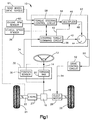
- Fig. 1 is a block diagram of a torque steer compensation system made in accordance with the present invention.
- Referring to Fig. 1, a vehicle torque
steer compensation system 10, in accordance with the present invention, includes avehicle steering wheel 12 connected to aninput shaft 14. Apinion gear 16 is connected to anoutput shaft 18. Theinput shaft 14 is coupled to theoutput shaft 18 through atorsion bar 20. Thetorsion bar 20 twists in response to torque applied to thevehicle steering wheel 12 and permits relative rotation between theinput shaft 14 and theoutput shaft 18. Stops, not shown, limit the amount of relative rotation between theinput shaft 14 and theoutput shaft 18 in a manner known in the art. - The
pinion gear 16 has helical gear teeth (not shown) which are meshingly engaged with straight cut gear teeth (not shown) on a linear steering member orrack 22. Therack 22 is coupled to vehiclesteerable wheels pinion gear 16 together with therack 22 forms a rack and pinion gear set. - The vehicle's
engine 27 is drivably coupled to thewheels wheels - When the
steering wheel 12 is turned, the rack and pinion gear set converts the rotary motion of thesteering 22 moves linearly, thesteerable wheels electric assist motor 28 is drivingly connected with therack 22 through, preferably, a ball-nut drive arrangement (not shown). Themotor 28, when energized, provides power assist torque to aid a vehicle driver in steering movement of therack 22 and, in turn, steering of the vehicle. - A
shaft position sensor 30 is operatively connected across theinput shaft 14 and theoutput shaft 18. Theshaft position sensor 30, in combination with thetorsion bar 20, form atorque sensor 32. Theshaft position sensor 30 provides an output signal online 34 having a value indicative of the relative rotational position between theinput shaft 14 and theoutput shaft 18. This relative rotational position between theinput shaft 14 and theoutput shaft 18 is indicative of the steering torque applied by the vehicle operator to thevehicle steering wheel 12. Therefore, the value of the output signal online 34 from theshaft position sensor 30 is indicative of the value or amount of steering torque applied to thevehicle steering wheel 12 and is referred to as theapplied steering torque. - The applied steering torque signal on
line 34 is connected to a steeringtorque command circuit 36. The steeringtorque command circuit 36 determines the amount of desired assist torque to be provided by themotor 28 and provides atorque command output 40 having a value indicative of the determined amount of desired torque assist. Thetorque command output 40 is a function of two parameters: (i) the value of the applied steering torque; and (ii) vehicle speed. - A
vehicle speed sensor 38 provides a vehicle speed output signal to thetorque command circuit 36 having a value indicative of the sensed vehicle speed. Typically, the amount of torque assist desired from themotor 28 decreases as vehicle speed increases. This is referred to in the art as "speed proportional steering." In addition to thetorque command output 40, the steeringtorque command circuit 36 provides asign output 42 which has a sign value indicative of the direction the applied steering torque (i.e., left turn or right turn) indicated by the output online 34 of thetorque sensor 32. The operation of a torque command circuit, such ascircuit 36, for control of an electric assist motor in response to applied steering torque and vehicle speed is known in the art and a detailed description of such operation is not discussed herein in detail. An example of a torque command circuit in accordance with the present invention is described in U.S. Patent No. 5,257,828 to Miller et al., which is hereby fully incorporated herein by reference. - The
output 40 of the steeringtorque command circuit 36 is connected to one input of asumming circuit 44. Amultiplier circuit 46 provides a torquesteer compensation output 48 which is connected to another input of thesumming circuit 44. Thesumming circuit 44 provides a compensatedtorque command output 50 which is equal to the sum of the torque command value onoutput 40 and the torque steer compensation value onoutput 48. The value of the compensatedtorque command output 50 is the value of the assist torque needed to cause themotor 28 to: 1) provide the desired steering assist torque (output 40); and 2) compensate for the torque steer effect on the vehicle (output 48). - The torque
steer compensation output 48 is the value of thesign output 42 times the value of atorque steer output 56 provided by a torquesteer control circuit 58. The torquesteer control circuit 58 determines the value of thetorque steer output 56 in response to: 1) vehicle speed sensed by thevehicle speed sensor 38; and 2) vehicle engine r.p.m. sensed by an engine r.p.m.sensor 60. In accordance with a preferred embodiment, the torquesteer control circuit 58, along with themultiplier 46, summingcircuit 44, and steeringtorque command circuit 36 are all programmed in amicrocomputer controller 62. The engine speed is indicative of the amount of torque steer. - In accordance with an alternative embodiment of the present invention, a road wheel
drive torque sensor 61 is operatively coupled between thevehicle engine 27 and the drivenwheels steer control circuit 58 having a characteristic indicative of the drive torque being applied to the drivenwheels - The functional relationship between the value of the torque
steer compensation output 56 and vehicle speed fromsensor 38 and engine r.p.m. fromsensor 60 or road wheel drive torque fromsensor 61 is dependent upon the particular vehicle platform of interest. It is anticipated that each vehicle platform will have an associated functional relationship. For a particular vehicle platform of interest, the torque steer compensation functional relationship may be determined empirically and stored in the form of an internal look-up table (memory) in themicrocomputer controller 62. Alternatively, the torque steer compensation functional relationship may be defined by an equation stored in thecontroller 62. - The
torque compensating output 50 provided by the summingcircuit 44 is connected to adrive control circuit 52. Thedrive control circuit 52 uses the torque compensatedoutput 50 in controlling the motor energization current and the motor direction. Amotor drive output 54 is provided to themotor 28 to energize themotor 28 which causes the motor to develop the compensated torque assist, i.e., torque assist compensated for any sensed torque steer effect. - Although the present invention has been described with regard to an electric power assist steering system, the invention is not limited to such a system. The present invention may be used with equal utility in a front wheel drive or all wheel drive vehicle having a hydraulic power steering system. In a hydraulic system, instead of an electrically controlled electric assist motor, hydraulic differential pressure is electrically controlled in response to measured engine r.p.m. or sensed road wheel drive torque to compensate for vehicle torque steer. Electric control of a hydraulic assist steering system is accomplished through electrical control of a valve between a pump and the hydraulic assist device.
- From the above description of the invention, those skilled in the art will perceive improvements, changes, and modifications. Such improvements, changes, and modifications within the skill of the art are intended to be covered by the appended claims. According to its broadest aspect the invention relates to:
- 10. An apparatus for compensating for torque steer in a vehicle having a power assist steering system, said apparatus comprising:
- means for sensing an operating characteristic of a vehicle indicative of torque steer; and
- means for sensing an operator applied steering torque.
- It should be noted that the objects and advantages of the invention may be attained by means of any compatible combination(s) particularly pointed out in the items of the following summary of the invention and the appended claims.
-
- 1. An apparatus for compensating for torque steer in a vehicle having a power assist steering system, said apparatus comprising:
- means for sensing an operating characteristic of a vehicle indicative of torque steer;
- means for sensing an operator applied steering torque; and
- control means for controlling the power assist steering system in response to the sensed operator applied steering torque and in response to the sensed operating characteristic indicative of torque steer so as to compensate for torque steer.
- 2. The apparatus wherein said means for sensing an operating characteristic of the vehicle indicative of torque steer senses engine rotations-per-minute of the vehicle engine.
- 3. The apparatus wherein said apparatus further includes means for sensing vehicle speed, said control means being further responsive to sensed vehicle speed to compensate for said torque steer.
- 4. The apparatus wherein said means for sensing an operating characteristic of the vehicle indicative of torque steer senses road wheel drive torque.
- 5. The apparatus wherein said apparatus further includes means for sensing vehicle speed, said control means being further responsive to sensed vehicle speed to compensate for said torque steer.
- 6. The apparatus wherein said power assist means is an electric motor.
- 7. The apparatus wherein said power assist means is a hydraulic device.
- 8. A vehicle power assist steering system comprising:
- sensing means for sensing rotations-per-minute (r.p.m.) of a vehicle engine;
- torque sensing means for sensing steering torque applied to a vehicle steering wheel by a vehicle operator;
- an electric assist motor for providing a steering assist force to assist the vehicle operator in steering the vehicle;
- control means for controlling said electric assist motor in response to the sensed applied steering torque and in response to the sensed engine r.p.m. to compensate for torque steer.
- 9. A vehicle power assist steering system comprising:
- sensing means for sensing road wheel drive torque;
- torque sensing means for sensing steering torque applied to a vehicle steering wheel by a vehicle operator;
- an electric assist motor for providing a steering assist force to assist the vehicle operator in steering the vehicle;
- control means for controlling said electric assist motor in response to the sensed applied steering torque and in response to the sensed road wheel drive torque to compensate for torque steer.
- 10. A method for compensating torque steer in a vehicle power assist steering system, said method comprising the steps of:
- sensing a vehicle operating characteristic indicative of torque steer;
- sensing applied steering torque by a vehicle operator;
- controlling the power assist steering system in response to said sensed applied steering torque and said sensed operating characteristic indicative of torque steer so as to compensate for torque steer.
- 11. The method wherein said step of sensing an operating characteristic indicative of torque steer includes the step of sensing rotations-per-minute of the vehicle engine.
- 12. The method and apparatus further including the step of sensing vehicle speed, said step of controlling is further responsive to said sensed vehicle speed.
- 13. The method wherein said step of sensing an operating characteristic indicative of torque steer includes the step of sensing road wheel drive torque.
- 14. The method further including the step of sensing vehicle speed, said step of controlling is further responsive to said sensed vehicle speed.
Claims (10)
- An apparatus for compensating for torque steer in a vehicle having a power assist steering system, said apparatus comprising:means for sensing an operating characteristic of a vehicle indicative of torque steer;means for sensing an operator applied steering torque; andcontrol means for controlling the power assist steering system in response to the sensed operator applied steering torque and in response to the sensed operating characteristic indicative of torque steer so as to compensate for torque steer.
- The apparatus of claim 1 wherein said means for sensing an operating characteristic of the vehicle indicative of torque steer senses engine rotations-per-minute of the vehicle engine.
- The apparatus of claim 2 wherein said apparatus further includes means for sensing vehicle speed, said control means being further responsive to sensed vehicle speed to compensate for said torque steer.
- The apparatus of claim 1 wherein said means for sensing an operating characteristic of the vehicle indicative of torque steer senses road wheel drive torque.
- The apparatus of claim 4 wherein said apparatus further includes means for sensing vehicle speed, said control means being further responsive to sensed vehicle speed to compensate for said torque steer,
wherein preferably said power assist means is an electric motor, and
wherein preferably said power assist means is a hydraulic device. - A vehicle power assist steering system comprising:sensing means for sensing rotations-per-minute (r.p.m.) of a vehicle engine;torque sensing means for sensing steering torque applied to a vehicle steering wheel by a vehicle operator;an electric assist motor for providing a steering assist force to assist the vehicle operator in steering the vehicle;control means for controlling said electric assist motor in response to the sensed applied steering torque and in response to the sensed engine r.p.m. to compensate for torque steer.
- A vehicle power assist steering system comprising:sensing means for sensing road wheel drive torque;torque sensing means for sensing steering torque applied to a vehicle steering wheel by a vehicle operator;an electric assist motor for providing a steering assist force to assist the vehicle operator in steering the vehicle;control means for controlling said electric assist motor in response to the sensed applied steering torque and in response to the sensed road wheel drive torque to compensate for torque steer.
- A method for compensating torque steer in a vehicle power assist steering system, said method comprising the steps of:sensing a vehicle operating characteristic indicative of torque steer;sensing applied steering torque by a vehicle operator;controlling the power assist steering system in response to said sensed applied steering torque and said sensed operating characteristic indicative of torque steer so as to compensate for torque steer.
- The method of claim 8 wherein said step of sensing an operating characteristic indicative of torque steer includes the step of sensing rotations-per-minute of the vehicle engine,
further preferably including the step of sensing vehicle speed, said step of controlling is further responsive to said sensed vehicle speed,
wherein preferably said step of sensing an operating characteristic indicative of torque steer includes the step of sensing road wheel drive torque, and
further preferably including the step of sensing vehicle speed, said step of controlling is further responsive to said sensed vehicle speed. - An apparatus for compensating for torque steer in a vehicle having a power assist steering system, said apparatus comprising:means for sensing an operating characteristic of a vehicle indicative of torque steer; andmeans for sensing an operator applied steering torque.
Applications Claiming Priority (2)
| Application Number | Priority Date | Filing Date | Title |
|---|---|---|---|
| US594253 | 1996-01-30 | ||
| US08/594,253 US6032755A (en) | 1996-01-30 | 1996-01-30 | Method and apparatus for compensating torque steer |
Publications (3)
| Publication Number | Publication Date |
|---|---|
| EP0787642A2 true EP0787642A2 (en) | 1997-08-06 |
| EP0787642A3 EP0787642A3 (en) | 1998-08-19 |
| EP0787642B1 EP0787642B1 (en) | 2004-05-06 |
Family
ID=24378155
Family Applications (1)
| Application Number | Title | Priority Date | Filing Date |
|---|---|---|---|
| EP96120210A Expired - Lifetime EP0787642B1 (en) | 1996-01-30 | 1996-12-16 | Method and apparatus for compensating torque steer |
Country Status (5)
| Country | Link |
|---|---|
| US (1) | US6032755A (en) |
| EP (1) | EP0787642B1 (en) |
| JP (1) | JPH09207802A (en) |
| BR (1) | BR9700755A (en) |
| DE (1) | DE69632387T2 (en) |
Cited By (8)
| Publication number | Priority date | Publication date | Assignee | Title |
|---|---|---|---|---|
| EP1031493A1 (en) * | 1997-11-12 | 2000-08-30 | Koyo Seiko Co., Ltd. | A steering device for vehicles |
| FR2801270A1 (en) * | 1999-11-23 | 2001-05-25 | Renault | Automatic steering correction system, for power assisted steering, uses steering rack casing displacement to correct transient deflections, while countering driver reaction |
| FR2835232A1 (en) * | 2002-01-31 | 2003-08-01 | Koyo Seiko Co | SELF-ALIGNING TORQUE CORRECTION DEVICE FOR A VEHICLE AND ELECTRICAL ASSISTED STEERING DEVICE |
| WO2004012978A1 (en) * | 2002-07-31 | 2004-02-12 | Daimlerchrysler Ag | Method for determining a steering torque that is active during the actuation of a steering wheel in motor vehicles |
| EP1767437A1 (en) * | 2005-09-22 | 2007-03-28 | Volkswagen Aktiengesellschaft | Steering-pull compensation device for motor vehicle |
| EP1800994A1 (en) * | 2004-10-14 | 2007-06-27 | Toyota Jidosha Kabushiki Kaisha | Controller of electric power steering device of vehicle in which steered wheels are driven |
| US7433768B2 (en) | 2002-07-31 | 2008-10-07 | Daimler Ag | Method for determining a steering-wheel torque |
| DE102013220632A1 (en) | 2013-10-14 | 2015-04-16 | Volkswagen Aktiengesellschaft | Device with a cardan shaft assembly and a drive train with universal joint shafts of different lengths |
Families Citing this family (26)
| Publication number | Priority date | Publication date | Assignee | Title |
|---|---|---|---|---|
| JP3517863B2 (en) * | 1997-02-07 | 2004-04-12 | トヨタ自動車株式会社 | Steering control device |
| JP3649312B2 (en) * | 1997-09-13 | 2005-05-18 | 本田技研工業株式会社 | Driving force transmission device for hybrid vehicle |
| JP3105847B2 (en) * | 1997-11-04 | 2000-11-06 | 本田技研工業株式会社 | Steering wheel control structure for electrically steered vehicles |
| JP3853943B2 (en) * | 1997-11-12 | 2006-12-06 | 株式会社ジェイテクト | Vehicle steering device |
| JP3344463B2 (en) * | 1998-04-27 | 2002-11-11 | トヨタ自動車株式会社 | Vehicle steering control device |
| US6661191B2 (en) | 2002-01-30 | 2003-12-09 | Visteon Global Technologies, Inc. | Method and apparatus for compensating drive current for an electric motor vehicle steering system |
| US7272478B2 (en) * | 2003-02-26 | 2007-09-18 | General Motors Corporation | Control system for active attenuation of torque-steer via electric power steering |
| US6868934B2 (en) * | 2003-07-09 | 2005-03-22 | Honda Giken Kogyo Kabushiki Kaisha | Variable power steering assist using driver grip pressure |
| JP4400270B2 (en) * | 2004-03-19 | 2010-01-20 | 日産自動車株式会社 | Steering angle ratio control device for vehicle |
| US7532966B2 (en) * | 2004-08-20 | 2009-05-12 | General Motors Corporation | Torque steer compensation algorithm |
| JP4639769B2 (en) | 2004-11-18 | 2011-02-23 | 日産自動車株式会社 | Torque steer suppression structure for vehicle |
| DE102005007307A1 (en) * | 2005-02-16 | 2006-08-17 | Zf Lenksysteme Gmbh | Steering element for motor vehicle has servomechanism and steering wheel and exhibits automatic compensation device for compensating acting braking moment on steering wheel |
| JP2006273266A (en) * | 2005-03-30 | 2006-10-12 | Denso Corp | Occupant protection device |
| JP4810965B2 (en) * | 2005-10-19 | 2011-11-09 | トヨタ自動車株式会社 | Vehicle that suppresses vehicle deflection due to drive torque difference between left and right wheels |
| DE102005057938A1 (en) * | 2005-12-05 | 2007-06-06 | Zf Lenksysteme Gmbh | Method for operating power steering at motor vehicle, involves addition of compensation moment for compensation of brake pull during strong acceleration of vehicle while determining delivering reference support moment of electric motor |
| JP4108713B2 (en) * | 2006-03-17 | 2008-06-25 | 三菱電機株式会社 | Electric power steering control device |
| DE102006015636B4 (en) * | 2006-04-04 | 2011-04-28 | Volkswagen Ag | Method for compensating for Schiefzieheffekten on a motor vehicle via the vehicle steering and this suitable device |
| US7970513B2 (en) * | 2006-06-15 | 2011-06-28 | Advics Co., Ltd. | Steering control apparatus for a vehicle |
| JP4835986B2 (en) * | 2006-06-15 | 2011-12-14 | 株式会社アドヴィックス | Electric steering control device |
| DE102006044088B4 (en) * | 2006-09-20 | 2009-09-24 | Ford Global Technologies, LLC, Dearborn | Method for compensating drive influences of a drive train of a motor vehicle |
| DE102007001638A1 (en) | 2007-01-11 | 2008-07-17 | Zf Lenksysteme Gmbh | Method for operating a power steering system |
| DE102007055773A1 (en) | 2007-12-12 | 2009-06-18 | Zf Lenksysteme Gmbh | Method for operating power steering for motor vehicle, involves providing electric motor for applying steering assistance moment in dependence of sensing hand moment, and controlling and regulating unit |
| JP2010254030A (en) * | 2009-04-22 | 2010-11-11 | Jtekt Corp | Power steering device |
| US8682532B2 (en) | 2011-07-22 | 2014-03-25 | Honda Motor Co., Ltd. | Vehicle including friction control device and methods |
| US10053109B2 (en) | 2016-02-26 | 2018-08-21 | Honda Motor Co., Ltd. | Systems and methods for controlling a vehicle including friction control device |
| DE102018210388A1 (en) | 2018-06-26 | 2020-01-02 | Bayerische Motoren Werke Aktiengesellschaft | Method for controlling and / or regulating a steering system of a motor vehicle |
Citations (1)
| Publication number | Priority date | Publication date | Assignee | Title |
|---|---|---|---|---|
| DE19536989A1 (en) * | 1994-10-04 | 1996-04-11 | Honda Motor Co Ltd | Servo-controlled steering for motor vehicle driven-steered wheels |
Family Cites Families (16)
| Publication number | Priority date | Publication date | Assignee | Title |
|---|---|---|---|---|
| KR920007039B1 (en) * | 1985-02-02 | 1992-08-24 | 가부시기가이샤 히다찌세이사꾸쇼 | Electro-motive power steering system |
| JPH07100450B2 (en) * | 1985-11-08 | 1995-11-01 | 自動車機器株式会社 | Power steering control device |
| EP0231665B1 (en) * | 1985-12-27 | 1991-07-24 | Aisin-Warner Kabushiki Kaisha | Control apparatus for four-wheel drive vehicle with center differential mechanism |
| JPH0665550B2 (en) * | 1986-01-08 | 1994-08-24 | 株式会社日立製作所 | Power steering control device |
| JPS62182873A (en) * | 1986-02-05 | 1987-08-11 | Shin Nikkei Co Ltd | Plotting system for fitting |
| JPH0288362A (en) * | 1988-09-26 | 1990-03-28 | Mitsubishi Electric Corp | Power steering device |
| JPH07108665B2 (en) * | 1988-11-14 | 1995-11-22 | 自動車機器株式会社 | Control method for power steering apparatus |
| US5291962A (en) * | 1989-11-07 | 1994-03-08 | Hino Jidosha Kogyo Kabushiki Kaisha | Power steering device for use in motor vehicles |
| JP2969874B2 (en) * | 1990-09-17 | 1999-11-02 | 日産自動車株式会社 | Steering angle control device |
| JP3046108B2 (en) * | 1991-08-26 | 2000-05-29 | 富士重工業株式会社 | Steering force control method for vehicle with differential limiting device |
| DE69217084T2 (en) * | 1991-10-10 | 1997-05-07 | Koyo Seiko Co | Electric power steering |
| US5528497A (en) * | 1992-09-16 | 1996-06-18 | Honda Giken Kogyo Kabushiki Kaisha | Vehicle steering control system |
| JP3182472B2 (en) * | 1993-06-10 | 2001-07-03 | 本田技研工業株式会社 | Power steering device |
| US5417298A (en) * | 1993-07-07 | 1995-05-23 | Honda Giken Kohyo Kabushiki Kaisha | Torque distribution control apparatus for vehicle |
| JP3034430B2 (en) * | 1994-07-27 | 2000-04-17 | 本田技研工業株式会社 | Steering reaction force control device for vehicle steering system |
| US5623409A (en) * | 1994-10-31 | 1997-04-22 | Trw Inc. | Method and apparatus for non-linear damping of an electric assist steering system for vehicle yaw rate control |
-
1996
- 1996-01-30 US US08/594,253 patent/US6032755A/en not_active Expired - Lifetime
- 1996-12-16 DE DE69632387T patent/DE69632387T2/en not_active Expired - Lifetime
- 1996-12-16 EP EP96120210A patent/EP0787642B1/en not_active Expired - Lifetime
-
1997
- 1997-01-23 BR BR9700755A patent/BR9700755A/en not_active IP Right Cessation
- 1997-01-30 JP JP9016624A patent/JPH09207802A/en active Pending
Patent Citations (1)
| Publication number | Priority date | Publication date | Assignee | Title |
|---|---|---|---|---|
| DE19536989A1 (en) * | 1994-10-04 | 1996-04-11 | Honda Motor Co Ltd | Servo-controlled steering for motor vehicle driven-steered wheels |
Non-Patent Citations (1)
| Title |
|---|
| "TORQUE STEER CONTROL SYSTEM" RESEARCH DISCLOSURE, no. 327, 1 July 1991, EMSWORTH, GB, page 488 XP000258688 * |
Cited By (11)
| Publication number | Priority date | Publication date | Assignee | Title |
|---|---|---|---|---|
| EP1031493A1 (en) * | 1997-11-12 | 2000-08-30 | Koyo Seiko Co., Ltd. | A steering device for vehicles |
| EP1031493A4 (en) * | 1997-11-12 | 2004-05-12 | Koyo Seiko Co | A steering device for vehicles |
| FR2801270A1 (en) * | 1999-11-23 | 2001-05-25 | Renault | Automatic steering correction system, for power assisted steering, uses steering rack casing displacement to correct transient deflections, while countering driver reaction |
| FR2835232A1 (en) * | 2002-01-31 | 2003-08-01 | Koyo Seiko Co | SELF-ALIGNING TORQUE CORRECTION DEVICE FOR A VEHICLE AND ELECTRICAL ASSISTED STEERING DEVICE |
| WO2004012978A1 (en) * | 2002-07-31 | 2004-02-12 | Daimlerchrysler Ag | Method for determining a steering torque that is active during the actuation of a steering wheel in motor vehicles |
| US7433768B2 (en) | 2002-07-31 | 2008-10-07 | Daimler Ag | Method for determining a steering-wheel torque |
| EP1800994A1 (en) * | 2004-10-14 | 2007-06-27 | Toyota Jidosha Kabushiki Kaisha | Controller of electric power steering device of vehicle in which steered wheels are driven |
| EP1800994B1 (en) * | 2004-10-14 | 2012-03-28 | Toyota Jidosha Kabushiki Kaisha | Controller of electric power steering device of vehicle in which steered wheels are driven |
| EP1767437A1 (en) * | 2005-09-22 | 2007-03-28 | Volkswagen Aktiengesellschaft | Steering-pull compensation device for motor vehicle |
| DE102013220632A1 (en) | 2013-10-14 | 2015-04-16 | Volkswagen Aktiengesellschaft | Device with a cardan shaft assembly and a drive train with universal joint shafts of different lengths |
| DE102013220632B4 (en) | 2013-10-14 | 2018-04-26 | Volkswagen Aktiengesellschaft | Device with a cardan shaft assembly and a drive train with universal joint shafts of different lengths |
Also Published As
| Publication number | Publication date |
|---|---|
| DE69632387T2 (en) | 2005-05-04 |
| US6032755A (en) | 2000-03-07 |
| BR9700755A (en) | 1998-11-10 |
| JPH09207802A (en) | 1997-08-12 |
| EP0787642B1 (en) | 2004-05-06 |
| EP0787642A3 (en) | 1998-08-19 |
| DE69632387D1 (en) | 2004-06-09 |
Similar Documents
| Publication | Publication Date | Title |
|---|---|---|
| US6032755A (en) | Method and apparatus for compensating torque steer | |
| EP0596167B1 (en) | Variable ratio steering system for a motor vehicle | |
| EP0190678B1 (en) | Method of operating electric power assisted steering systems and electric power assisted steering system | |
| US4834203A (en) | Electric power steering system | |
| US6782968B2 (en) | Automatic steering apparatus for vehicle and control method of same | |
| US4909343A (en) | Electric power steering system | |
| US7792619B2 (en) | Electrically driven power steering system for vehicle | |
| EP1304276B1 (en) | Steering angle ratio control system and method | |
| EP1559633B1 (en) | Method and apparatus for controlling an electric assist motor using a modified blending filter | |
| US5398953A (en) | Electrically operated power steering system | |
| EP1539559B1 (en) | Controlling an assist motor using a blending filter | |
| JP4275752B2 (en) | Steering device for automobile | |
| EP0490673B1 (en) | Material handling vehicle steering system | |
| US6112845A (en) | Reactive steering control system | |
| EP0671310A1 (en) | Method and apparatus for controlling an electric assist steering system | |
| EP0775624A2 (en) | Steering system for automobile | |
| EP0779199B1 (en) | A steering control apparatus utilizing a hysteresis control of a steering torque | |
| EP1125822B1 (en) | Vehicle electric power assist steering system and method using angle based torque estimation | |
| EP0810142A3 (en) | Motor-driven power steering system for motor vehicle | |
| US20010001842A1 (en) | Reverse determination method of vehicle and vehicle control apparatus | |
| US4875541A (en) | Electric power steering system | |
| US6072293A (en) | Steering control system for vehicle | |
| EP0164842A2 (en) | Power assistance steering systems for vehicles | |
| US5096011A (en) | Steering gear and system for automotive vehicle | |
| JP2860422B2 (en) | Electric power steering device |
Legal Events
| Date | Code | Title | Description |
|---|---|---|---|
| PUAI | Public reference made under article 153(3) epc to a published international application that has entered the european phase |
Free format text: ORIGINAL CODE: 0009012 |
|
| AK | Designated contracting states |
Kind code of ref document: A2 Designated state(s): DE FR GB IT |
|
| PUAL | Search report despatched |
Free format text: ORIGINAL CODE: 0009013 |
|
| AK | Designated contracting states |
Kind code of ref document: A3 Designated state(s): DE FR GB IT |
|
| 17P | Request for examination filed |
Effective date: 19990218 |
|
| 17Q | First examination report despatched |
Effective date: 20000308 |
|
| GRAP | Despatch of communication of intention to grant a patent |
Free format text: ORIGINAL CODE: EPIDOSNIGR1 |
|
| RAP1 | Party data changed (applicant data changed or rights of an application transferred) |
Owner name: TRW AUTOMOTIVE U.S. LLC |
|
| GRAS | Grant fee paid |
Free format text: ORIGINAL CODE: EPIDOSNIGR3 |
|
| GRAA | (expected) grant |
Free format text: ORIGINAL CODE: 0009210 |
|
| AK | Designated contracting states |
Kind code of ref document: B1 Designated state(s): DE FR GB IT |
|
| REG | Reference to a national code |
Ref country code: GB Ref legal event code: FG4D |
|
| REF | Corresponds to: |
Ref document number: 69632387 Country of ref document: DE Date of ref document: 20040609 Kind code of ref document: P |
|
| ET | Fr: translation filed | ||
| PLBE | No opposition filed within time limit |
Free format text: ORIGINAL CODE: 0009261 |
|
| STAA | Information on the status of an ep patent application or granted ep patent |
Free format text: STATUS: NO OPPOSITION FILED WITHIN TIME LIMIT |
|
| 26N | No opposition filed |
Effective date: 20050208 |
|
| PGFP | Annual fee paid to national office [announced via postgrant information from national office to epo] |
Ref country code: IT Payment date: 20081213 Year of fee payment: 13 |
|
| PGFP | Annual fee paid to national office [announced via postgrant information from national office to epo] |
Ref country code: FR Payment date: 20081205 Year of fee payment: 13 |
|
| PGFP | Annual fee paid to national office [announced via postgrant information from national office to epo] |
Ref country code: GB Payment date: 20081110 Year of fee payment: 13 |
|
| GBPC | Gb: european patent ceased through non-payment of renewal fee |
Effective date: 20091216 |
|
| REG | Reference to a national code |
Ref country code: FR Ref legal event code: ST Effective date: 20100831 |
|
| PG25 | Lapsed in a contracting state [announced via postgrant information from national office to epo] |
Ref country code: FR Free format text: LAPSE BECAUSE OF NON-PAYMENT OF DUE FEES Effective date: 20091231 |
|
| PG25 | Lapsed in a contracting state [announced via postgrant information from national office to epo] |
Ref country code: GB Free format text: LAPSE BECAUSE OF NON-PAYMENT OF DUE FEES Effective date: 20091216 |
|
| PG25 | Lapsed in a contracting state [announced via postgrant information from national office to epo] |
Ref country code: IT Free format text: LAPSE BECAUSE OF NON-PAYMENT OF DUE FEES Effective date: 20091216 |
|
| PGFP | Annual fee paid to national office [announced via postgrant information from national office to epo] |
Ref country code: DE Payment date: 20151229 Year of fee payment: 20 |
|
| REG | Reference to a national code |
Ref country code: DE Ref legal event code: R071 Ref document number: 69632387 Country of ref document: DE |