EP0787620B1 - Electric vehicle controller - Google Patents
Electric vehicle controller Download PDFInfo
- Publication number
- EP0787620B1 EP0787620B1 EP96112835A EP96112835A EP0787620B1 EP 0787620 B1 EP0787620 B1 EP 0787620B1 EP 96112835 A EP96112835 A EP 96112835A EP 96112835 A EP96112835 A EP 96112835A EP 0787620 B1 EP0787620 B1 EP 0787620B1
- Authority
- EP
- European Patent Office
- Prior art keywords
- voltage
- filter capacitor
- trolley
- power
- regenerative
- Prior art date
- Legal status (The legal status is an assumption and is not a legal conclusion. Google has not performed a legal analysis and makes no representation as to the accuracy of the status listed.)
- Expired - Lifetime
Links
Images

Classifications
-
- B—PERFORMING OPERATIONS; TRANSPORTING
- B60—VEHICLES IN GENERAL
- B60L—PROPULSION OF ELECTRICALLY-PROPELLED VEHICLES; SUPPLYING ELECTRIC POWER FOR AUXILIARY EQUIPMENT OF ELECTRICALLY-PROPELLED VEHICLES; ELECTRODYNAMIC BRAKE SYSTEMS FOR VEHICLES IN GENERAL; MAGNETIC SUSPENSION OR LEVITATION FOR VEHICLES; MONITORING OPERATING VARIABLES OF ELECTRICALLY-PROPELLED VEHICLES; ELECTRIC SAFETY DEVICES FOR ELECTRICALLY-PROPELLED VEHICLES
- B60L9/00—Electric propulsion with power supply external to the vehicle
- B60L9/16—Electric propulsion with power supply external to the vehicle using AC induction motors
- B60L9/18—Electric propulsion with power supply external to the vehicle using AC induction motors fed from DC supply lines
- B60L9/22—Electric propulsion with power supply external to the vehicle using AC induction motors fed from DC supply lines polyphase motors
-
- B—PERFORMING OPERATIONS; TRANSPORTING
- B60—VEHICLES IN GENERAL
- B60L—PROPULSION OF ELECTRICALLY-PROPELLED VEHICLES; SUPPLYING ELECTRIC POWER FOR AUXILIARY EQUIPMENT OF ELECTRICALLY-PROPELLED VEHICLES; ELECTRODYNAMIC BRAKE SYSTEMS FOR VEHICLES IN GENERAL; MAGNETIC SUSPENSION OR LEVITATION FOR VEHICLES; MONITORING OPERATING VARIABLES OF ELECTRICALLY-PROPELLED VEHICLES; ELECTRIC SAFETY DEVICES FOR ELECTRICALLY-PROPELLED VEHICLES
- B60L7/00—Electrodynamic brake systems for vehicles in general
- B60L7/10—Dynamic electric regenerative braking
- B60L7/14—Dynamic electric regenerative braking for vehicles propelled by AC motors
-
- B—PERFORMING OPERATIONS; TRANSPORTING
- B60—VEHICLES IN GENERAL
- B60L—PROPULSION OF ELECTRICALLY-PROPELLED VEHICLES; SUPPLYING ELECTRIC POWER FOR AUXILIARY EQUIPMENT OF ELECTRICALLY-PROPELLED VEHICLES; ELECTRODYNAMIC BRAKE SYSTEMS FOR VEHICLES IN GENERAL; MAGNETIC SUSPENSION OR LEVITATION FOR VEHICLES; MONITORING OPERATING VARIABLES OF ELECTRICALLY-PROPELLED VEHICLES; ELECTRIC SAFETY DEVICES FOR ELECTRICALLY-PROPELLED VEHICLES
- B60L2200/00—Type of vehicles
- B60L2200/26—Rail vehicles
Definitions
- the present invention relates to an electric vehicle controller which is used in the control of a motor for driving an electric railway vehicle.
- Fig. 6 is a block diagram showing a conventional electric vehicle controller disclosed in Japanese Patent Laid-Open No. 2-26203.
- This electric vehicle controller includes a DC transformer 31 connected to a pantograph (not shown) for detecting a DC trolley voltage, an average value operation circuit 32 connected to this DC transformer 31 for obtaining an average value of the detected trolley voltages, and a storage circuit 34 connected to a brake command signal input terminal 33 for receiving a brake command signal and also connected to the average value operation circuit 32.
- the storage circuit 34 stores the average value of the trolley voltages at the time that a regenerative brake command has been input by the brake command signal.
- the electric vehicle controller further includes a current pattern generator 35 connected to the brake command input terminal 33 for generating a current pattern, based on the brake command signal, and a DC transformer 36 for filter capacitor voltage detection which is connected to a filter capacitor (not shown) for detecting the voltage of the filter capacitor.
- the electric vehicle controller further includes an overvoltage limiter 37, which is connected to the DC transformer 36 for filter capacitor voltage detection and also connected to the storage circuit 34.
- the overvoltage limiter 37 will output a current reducing voltage (negative value) if the filter capacitor voltage exceeds a predetermined value.
- the electric vehicle controller also includes an adder 38, which is connected to the overvoltage limiter 37 and the current pattern generator 35.
- the adder 38 serves as a current command circuit which performs addition of the outputs of the overvoltage limiter 37 and the current pattern generator 35.
- Fig. 7 shows the current reducing pattern of the overvoltage limiter 37.
- a current pattern is generated by the current pattern generator 35. If the output of the filter capacitor voltage detection DC transformer 36 exceeds a predetermined value, then the overvoltage limiter 37 will operate, and the adder 38 serving as a current command circuit will add the current pattern output and the current reducing output of the overvoltage limiter 37 and will output a current command signal.
- the trolley voltage is detected by the trolley voltage detection DC transformer 31 during coasting, and an average value of the detected trolley voltages is obtained by the average value operation circuit 32.
- the storage circuit 34 stores the average value of the trolley voltages transmitted from the average operation circuit 32. Then, based on the trolley voltage averaged value input to the storage circuit 34, the current reducing patterns shown in Fig. 7 will be selected as follows.
- a current reducing pattern 40 where the start point of the current reduction is lower than normal pattern 39, is selected, and the current reduction is performed by operating the overvoltage limiter 37 at a lower value of the filter capacitor voltage.
- a current reducing pattern 41 where the start point of the current reduction is higher than the normal pattern 39, is selected, and the current reduction is performed by operating the overvoltage limiter 37 at a higher value of the filter capacitor voltage.
- the overvoltage limiter 37 when the trolley voltage is high, it is assumed that there is no railway vehicle which becomes a load on the power supply side and that the trolley impedance is high, and the overvoltage limiter 37 is operated in its early stages. In addition, until the filter capacitor voltage is sufficiently reduced, the current reduction is performed so that the frequency that an overvoltage is applied to the filter capacitor is reduced, and consequently, the frequency that an overvoltage protecting device for the filter capacitor is operated is reduced. On the other hand, in the case where the trolley voltage is low, the number of the operations of the overvoltage limiter 37 itself is reduced so that regenerative control can be effectively performed.
- the conventional electric vehicle controller has the following problems, when it is constructed as described above.
- the object of the invention is to provide an electric vehicle controller which regulates a regenerative braking power by grasping the characteristic of a transforming station such as the existence of a load vehicle and thereby effectively controls regenerative braking.
- an electric vehicle controller according to claim 1.
- the regenerative braking power can be regulated while grasping the characteristic of a transforming station such as the existence of a load vehicle, and consequently, the regenerative braking can be effectively controlled.
- said trolley voltage detecting means is constituted by said filter capacitor voltage detector which detects the voltage of said filter capacitor when the control rectifying devices of said power converter circuit are not operated.
- the filter capacitor voltage detector can be used as the trolley voltage detecting means.
- said filter capacitor voltage detector serving as said trolley voltage detecting means detects the voltage of said filter capacitor between the time that said command is input from the operation table and the time that the control rectifying devices of said power converter circuit are operated.
- the regulation of said regenerative power is performed by increasing or decreasing the threshold value of the voltage of said filter capacitor.
- the regulation of said regenerative power is performed by regulating a rate of change of regenerative braking activation.
- the regenerative braking power can be regulated while grasping the characteristic of a transforming station such as the existence of a load vehicle, and consequently, the regenerative braking can be effectively controlled.
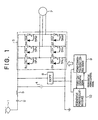
- the electric vehicle controller is equipped with a pantograph 1 for obtaining electric power from the trolley wire of a railway line, a DC breaker 2 for electrically disconnecting, an electric vehicle connected to the pantograph 1 and the trolley wire, a filter reactor (hereinafter referred as a FL) 3 connected to this DC breaker 2 for smoothing a DC current ripple obtained from the trolley wire, and a filter capacitor (hereinafter referred as a FC) 4 connected to this FL 3 for regulating a DC voltage.
- a filter reactor hereinafter referred as a FL
- FC filter capacitor
- the electric vehicle controller is further equipped with an inverter circuit 5 connected in series with the FL 3 and in parallel with a DC voltage detector to be described later.
- This inverter circuit 5 constitutes a power converter circuit constituting a three-phase inverter circuit, in which a positive electrode side element group of 5PU, 5PV, and 5PW of U, V, and W phases and a negative electrode side element group of 5NU, 5NV, and 5NW of U, V, and W phases are connected in series at intervals of each phase and in which all of the opposite ends of each of the serially connected U, V, and W phases are connected in parallel with the FC4.
- the inverter circuit 5 is equipped with control rectifying devices 5U, 5V, and 5W such as gate turn-off thyristors (hereinafter referred to as GTOs) provided on the positive electrode sides of the U, V, and W phases, control rectifying devices 5X, 5Y, and 5Z such as GTOs provided on the positive electrode sides of the U, V, and W phases, and diodes 6U, 6V, and 6W and diodes 6X, 6Y, and 6Z respectively connected in inverse-parallel with the control rectifying devices of each phase.
- the control rectifying device and the diode in inverse-parallel connection constitute each of the aforementioned positive electrode side element group of 5PU, 5PV, and 5PW and negative electrode side element group of 5NU, 5NV, and 5NW.
- a three-phase induction motor 7 which is a main motor for driving a railway vehicle at intervals of each phase.
- a DC voltage detector 8 (hereinafter referred to as a DCPT), connected in parallel with the inverter circuit 5, is a filter capacitor voltage detector provided for measuring a FC potential.
- This filter capacitor voltage detector in this embodiment, doubles as trolley voltage detecting means claimed in the appended claims, and detects the voltage of the filter capacitor when the control rectifying element of the power converter circuit is not operated, thereby constituting the trolley voltage detecting means.
- the trolley voltage detecting means of this invention may be constituted by a structure where the trolley voltage can be detected directly or indirectly and therefore the trolley voltage detecting means does not need to be limited to such a filter capacitor voltage detector.
- the DCPT 8 is equipped with a power converter circuit control device 9 and a regenerative power regulating element 10.
- the power converter circuit control device 9 commands the operative state of the control rectifying element so that the tractive force or braking force generated by the main motor is controlled to a target value.
- the regenerative power regulating device 10 monitors the FC voltage when the control rectifying devices of the power converter circuit are not operated, then sets a threshold value based on the difference between the monitored value and the DC rated trolley voltage, determines the regulation of regenerative power by comparing the FC voltage during actual regeneration with the threshold value, and outputs a regenerative power control signal to the power converter circuit control device.
- the power converter circuit control device 9 receives the regenerative power control signal, and actually controls the switching of the control rectifying devices 5U, 5V, and 5W and control rectifying devices 5X, 5Y, and 5Z so that the regenerative braking power can be increased and decreased.
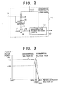
- Fig. 2 shows an embodiment of the generative power regulating device 10.
- This regenerative power regulating device 10 is equipped with a regenerative power pattern circuit 12 for receiving the output signal 11 of the DCPT8 shown in Fig. 1, a signal changing switch 13 for changing the output signal 11 of the DCPT8, based on a signal from the power converter circuit control device 9, and a hold circuit 14 connected to this switch 13 and the power converter circuit control device 9 for holding the signal sent from the power converter circuit control device 9.
- a signal 15 from the power converter circuit control device 9 is a signal representative of "during coasting.” With this signal 15, the switch 13 is turned off, except for the "during coasting" of the electric vehicle, and at the same time, the output 16 of the hold circuit 14 is held to a held value before that. That is, during coasting, the FC voltage appears on the output 16 of the hold circuit 14.
- the output terminal of the hold circuit 14 is connected to a subtracter 18, in which the DC rated trolley voltage 17 is subtracted from the output of the hold circuit 14.
- the output terminal of this subtracter 18 is connected to the regenerative power pattern circuit 12, and the value, obtained by subtracting the rated trolley voltage 17 from the output value 16 of the hold circuit 14, becomes an input (differential voltage) 19 to the regenerative power pattern circuit 12.
- the operation of the regenerative power pattern circuit 12 will be described with Fig. 3.
- the axis of abscissa represents the FC voltage and the axis of ordinate the regenerative power limiting value.
- the circuit 12 operates in the same way as before. According to this regenerative power pattern, the regenerative power starts to be limited when the FC voltage is 1650 V, and the regenerative power becomes zero when the FC voltage is 1800 V.
- the differential voltage 19 being 100 V
- the FC voltage is detected to be 1600 V
- a transforming station which supplies electric power to the DC trolley wire outputs a voltage higher than the DC rated trolley voltage.
- the regenerative power is regulated so as not to be limited at a FC voltage of 1650 V.
- the regenerative power starts to be limited when the FC voltage is more than 1730 V, and the regenerative power becomes zero when the FC voltage is 1800 V.
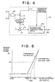
- Fig. 4 shows another embodiment of the regenerative power control device 10.
- reference numerals 11, 13, 14, and 16 to 20 are identical with or correspond to Fig. 2 and therefore a description is omitted.
- Reference numerals 21A and 21B denote a brake command (regenerative braking command from an operation table, etc.) and a start gate signal (start gate signal of inverter 5), respectively, which are output from the power converter circuit control device 9 of Fig. 1.
- Reference numeral 22 denotes an AND circuit, which performs the AND operation of the signals 21A and 21B and then outputs an on-off signal of the switch 13. On the output signal 16 of the hold circuit 14, the FC voltage appears between the time that the control command is input from the operation table and the time that the control rectifying devices of the power converter circuit are operated.
- the operation of the regenerative power pattern circuit 23 will be described with Fig. 5.
- the axis of abscissa represents the FC voltage and the axis of ordinate the time constant of the regenerative braking activation.
- the time constant of the regenerative braking activation is constant independently of the FC voltage.
- the differential voltage of Fig. 4 is 100 V, it is supposed that the DC rated trolley voltage has been highly output.
- the FC voltage is more than 1600 V the time constant is increased, and the FC voltage is 1700 V the time constant is increased by 4.5 times.
- the power converter circuit has been described as an inverter circuit 5, the same advantages as the aforementioned embodiments will be obtainable even for a chopper circuit.
- inverter circuit 5 which is a power converter circuit has been described as a 2-level inverter circuit, the same advantages as the aforementioned embodiments will be obtainable even for a 3-level inverter circuit.
- control rectifying devices of the inverter circuits 5U, 5V, 5W, 5X, 5Y, and 5Z have been described by using the GTOs, the same advantages as the aforementioned embodiments would be obtainable even if various semiconductor devices of arc extinguish types, such as transistors, field effect transistors, or insulated gate bipolar mode transistors, were used.
- diodes 6U, 6V, 6W, 6X, 6Y, and 6Z respectively connected in inverse-parallel with the control rectifying devices 5U, 5V, 5W, 5X, 5Y, and 5Z of the inverter circuit 5, have been described as separate elements, the same advantages of the aforementioned embodiments would be obtainable even if various semiconductor devices of arc extinguish types, such as a combination of a control rectifying element and a diode connected on the same element in inverse-parallel, were used.
Landscapes
- Engineering & Computer Science (AREA)
- Power Engineering (AREA)
- Transportation (AREA)
- Mechanical Engineering (AREA)
- Life Sciences & Earth Sciences (AREA)
- Sustainable Development (AREA)
- Sustainable Energy (AREA)
- Electric Propulsion And Braking For Vehicles (AREA)
- Control Of Ac Motors In General (AREA)
- Inverter Devices (AREA)
Description
- The present invention relates to an electric vehicle controller which is used in the control of a motor for driving an electric railway vehicle.
- Fig. 6 is a block diagram showing a conventional electric vehicle controller disclosed in Japanese Patent Laid-Open No. 2-26203.
- This electric vehicle controller includes a
DC transformer 31 connected to a pantograph (not shown) for detecting a DC trolley voltage, an averagevalue operation circuit 32 connected to thisDC transformer 31 for obtaining an average value of the detected trolley voltages, and astorage circuit 34 connected to a brake commandsignal input terminal 33 for receiving a brake command signal and also connected to the averagevalue operation circuit 32. Thestorage circuit 34 stores the average value of the trolley voltages at the time that a regenerative brake command has been input by the brake command signal. The electric vehicle controller further includes acurrent pattern generator 35 connected to the brakecommand input terminal 33 for generating a current pattern, based on the brake command signal, and aDC transformer 36 for filter capacitor voltage detection which is connected to a filter capacitor (not shown) for detecting the voltage of the filter capacitor. The electric vehicle controller further includes anovervoltage limiter 37, which is connected to theDC transformer 36 for filter capacitor voltage detection and also connected to thestorage circuit 34. Theovervoltage limiter 37 will output a current reducing voltage (negative value) if the filter capacitor voltage exceeds a predetermined value. The electric vehicle controller also includes anadder 38, which is connected to theovervoltage limiter 37 and thecurrent pattern generator 35. Theadder 38 serves as a current command circuit which performs addition of the outputs of theovervoltage limiter 37 and thecurrent pattern generator 35. - Fig. 7 shows the current reducing pattern of the
overvoltage limiter 37. - The operation of the conventional electric vehicle controller will hereinafter be described with Figs. 6 and 7.
- Based on the brake command signal which was input in the brake command
signal input terminal 33, a current pattern is generated by thecurrent pattern generator 35. If the output of the filter capacitor voltagedetection DC transformer 36 exceeds a predetermined value, then theovervoltage limiter 37 will operate, and theadder 38 serving as a current command circuit will add the current pattern output and the current reducing output of theovervoltage limiter 37 and will output a current command signal. - On the other hand, the trolley voltage is detected by the trolley voltage
detection DC transformer 31 during coasting, and an average value of the detected trolley voltages is obtained by the averagevalue operation circuit 32. At the time the brake command signal is input to the brake commandsignal input terminal 33, thestorage circuit 34 stores the average value of the trolley voltages transmitted from theaverage operation circuit 32. Then, based on the trolley voltage averaged value input to thestorage circuit 34, the current reducing patterns shown in Fig. 7 will be selected as follows. - First, in the case where the average value of the trolley voltages is high, a current reducing
pattern 40, where the start point of the current reduction is lower thannormal pattern 39, is selected, and the current reduction is performed by operating theovervoltage limiter 37 at a lower value of the filter capacitor voltage. On the other hand, in the case where the average value of the trolley voltages is low, a current reducingpattern 41, where the start point of the current reduction is higher than thenormal pattern 39, is selected, and the current reduction is performed by operating theovervoltage limiter 37 at a higher value of the filter capacitor voltage. - Thus, in the conventional electric vehicle controller, when the trolley voltage is high, it is assumed that there is no railway vehicle which becomes a load on the power supply side and that the trolley impedance is high, and the
overvoltage limiter 37 is operated in its early stages. In addition, until the filter capacitor voltage is sufficiently reduced, the current reduction is performed so that the frequency that an overvoltage is applied to the filter capacitor is reduced, and consequently, the frequency that an overvoltage protecting device for the filter capacitor is operated is reduced. On the other hand, in the case where the trolley voltage is low, the number of the operations of theovervoltage limiter 37 itself is reduced so that regenerative control can be effectively performed. - However, the conventional electric vehicle controller has the following problems, when it is constructed as described above.
- That is, although the rated value of the trolley voltage has been determined, an actual trolley voltage fluctuates from the rated value, due to a change in the output voltage of a transforming station, the positional relationship between the transforming station and the trolley wire, and the characteristic of the transforming station such as the existence of a load vehicle.
- Therefore, in a case where the trolley voltage is originally higher than the rated voltage, there is the problem that regenerative power is unnecessarily reduced even when a railway vehicle, which becomes a load, exists.
- In addition, in a case where the trolley voltage is originally lower than the rated voltage, there is the problem that the operation of the overvoltage limiter is delayed, the regenerative power becomes excessive, and a DC voltage rises, when there is no railway vehicle which becomes a load.
- This invention has been made in order to overcome the aforementioned problems. Accordingly, the object of the invention is to provide an electric vehicle controller which regulates a regenerative braking power by grasping the characteristic of a transforming station such as the existence of a load vehicle and thereby effectively controls regenerative braking.
- In accordance with an aspect of the present invention, there is provided an electric vehicle controller according to
claim 1. - With this arrangement, the regenerative braking power can be regulated while grasping the characteristic of a transforming station such as the existence of a load vehicle, and consequently, the regenerative braking can be effectively controlled.
- In a preferred form of the invention, said trolley voltage detecting means is constituted by said filter capacitor voltage detector which detects the voltage of said filter capacitor when the control rectifying devices of said power converter circuit are not operated.
- With this arrangement, the filter capacitor voltage detector can be used as the trolley voltage detecting means.
- In another preferred form of the invention, said filter capacitor voltage detector serving as said trolley voltage detecting means detects the voltage of said filter capacitor between the time that said command is input from the operation table and the time that the control rectifying devices of said power converter circuit are operated.
- In still another preferred form of the invention, the regulation of said regenerative power is performed by increasing or decreasing the threshold value of the voltage of said filter capacitor.
- In a further preferred form of the invention, the regulation of said regenerative power is performed by regulating a rate of change of regenerative braking activation.
- With these arrangements, the regenerative braking power can be regulated while grasping the characteristic of a transforming station such as the existence of a load vehicle, and consequently, the regenerative braking can be effectively controlled.
- The above and other objects and advantages will become apparent from the following detailed description when read in conjunction with the accompanying drawings wherein:
- Fig. 1 is a circuit diagram showing an embodiment of an electric vehicle controller of the present invention;
- Fig. 2 is a block diagram showing an embodiment of the regenerative power regulating device of the present invention;
- Fig. 3 is a diagram showing an example of the regenerative power reducing pattern of the present invention;
- Fig. 4 is a block diagram showing another embodiment of the regenerative power regulating device of the present invention;
- Fig. 5 is a diagram showing an example of the time constant of the regenerative braking activation of the present invention;
- Fig. 6 is a circuit diagram showing a conventional electric vehicle controller for three-phase induction motor control; and
- Fig. 7 is an explanatory diagram showing the operation of the electric vehicle controller for three-phase induction motor control.
-
- Referring to Fig. 1, there is shown a preferred embodiment of an electric vehicle controller in accordance with the present invention. The electric vehicle controller is equipped with a
pantograph 1 for obtaining electric power from the trolley wire of a railway line, a DC breaker 2 for electrically disconnecting, an electric vehicle connected to thepantograph 1 and the trolley wire, a filter reactor (hereinafter referred as a FL) 3 connected to this DC breaker 2 for smoothing a DC current ripple obtained from the trolley wire, and a filter capacitor (hereinafter referred as a FC) 4 connected to thisFL 3 for regulating a DC voltage. - The electric vehicle controller is further equipped with an
inverter circuit 5 connected in series with theFL 3 and in parallel with a DC voltage detector to be described later. Thisinverter circuit 5 constitutes a power converter circuit constituting a three-phase inverter circuit, in which a positive electrode side element group of 5PU, 5PV, and 5PW of U, V, and W phases and a negative electrode side element group of 5NU, 5NV, and 5NW of U, V, and W phases are connected in series at intervals of each phase and in which all of the opposite ends of each of the serially connected U, V, and W phases are connected in parallel with the FC4. - That is, the
inverter circuit 5 is equipped withcontrol rectifying devices diodes - On the output terminals of the
inverter circuit 5, that is, the intermediate connection points between the positive electrode side element group of 5PU, 5PV, and 5PW of U, V, and W phases and the negative electrode side element group of 5NU, 5NV, and 5NW of U, V, and W phases, there is connected a three-phase induction motor 7 which is a main motor for driving a railway vehicle at intervals of each phase. - A DC voltage detector 8 (hereinafter referred to as a DCPT), connected in parallel with the
inverter circuit 5, is a filter capacitor voltage detector provided for measuring a FC potential. This filter capacitor voltage detector, in this embodiment, doubles as trolley voltage detecting means claimed in the appended claims, and detects the voltage of the filter capacitor when the control rectifying element of the power converter circuit is not operated, thereby constituting the trolley voltage detecting means. Note that the trolley voltage detecting means of this invention may be constituted by a structure where the trolley voltage can be detected directly or indirectly and therefore the trolley voltage detecting means does not need to be limited to such a filter capacitor voltage detector. - The DCPT 8 is equipped with a power converter
circuit control device 9 and a regenerative power regulatingelement 10. In response to the command from the operation table or the FC voltage input from theDCPT 8, the power convertercircuit control device 9 commands the operative state of the control rectifying element so that the tractive force or braking force generated by the main motor is controlled to a target value. In response to the force line-regeneration signal from this power convertercircuit control device 9, the regenerative power regulatingdevice 10 monitors the FC voltage when the control rectifying devices of the power converter circuit are not operated, then sets a threshold value based on the difference between the monitored value and the DC rated trolley voltage, determines the regulation of regenerative power by comparing the FC voltage during actual regeneration with the threshold value, and outputs a regenerative power control signal to the power converter circuit control device. The power convertercircuit control device 9 receives the regenerative power control signal, and actually controls the switching of the control rectifyingdevices - Fig. 2 shows an embodiment of the generative power regulating
device 10. This regenerativepower regulating device 10 is equipped with a regenerativepower pattern circuit 12 for receiving theoutput signal 11 of the DCPT8 shown in Fig. 1, asignal changing switch 13 for changing theoutput signal 11 of the DCPT8, based on a signal from the power convertercircuit control device 9, and ahold circuit 14 connected to thisswitch 13 and the power convertercircuit control device 9 for holding the signal sent from the power convertercircuit control device 9. - A
signal 15 from the power convertercircuit control device 9 is a signal representative of "during coasting." With thissignal 15, theswitch 13 is turned off, except for the "during coasting" of the electric vehicle, and at the same time, theoutput 16 of thehold circuit 14 is held to a held value before that. That is, during coasting, the FC voltage appears on theoutput 16 of thehold circuit 14. The output terminal of thehold circuit 14 is connected to asubtracter 18, in which the DC ratedtrolley voltage 17 is subtracted from the output of thehold circuit 14. The output terminal of thissubtracter 18 is connected to the regenerativepower pattern circuit 12, and the value, obtained by subtracting the ratedtrolley voltage 17 from theoutput value 16 of thehold circuit 14, becomes an input (differential voltage) 19 to the regenerativepower pattern circuit 12. - Now, the operation of the regenerative
power pattern circuit 12 will be described with Fig. 3. In Fig. 3, the axis of abscissa represents the FC voltage and the axis of ordinate the regenerative power limiting value. Initially, when thedifferential voltage 19 of Fig. 2 is a zero voltage, thecircuit 12 operates in the same way as before. According to this regenerative power pattern, the regenerative power starts to be limited when the FC voltage is 1650 V, and the regenerative power becomes zero when the FC voltage is 1800 V. However, in the case of thedifferential voltage 19 being 100 V, that is, in the case of the DC rated trolley voltage being 1500 V, when the FC voltage is detected to be 1600 V, it is assumed that a transforming station which supplies electric power to the DC trolley wire outputs a voltage higher than the DC rated trolley voltage. The regenerative power is regulated so as not to be limited at a FC voltage of 1650 V. And, in the characteristic of Fig. 3, the regenerative power starts to be limited when the FC voltage is more than 1730 V, and the regenerative power becomes zero when the FC voltage is 1800 V. - According to this, when the FC voltage is 1700 V, the conventional operation has been limited to the regenerative power of 65%, the regenerative braking has not been operated effectively, and the quantity of the regenerative power has been reduced, however in this embodiment it becomes possible to perform a regenerative power operation of 100%.
- Fig. 4 shows another embodiment of the regenerative
power control device 10. In Fig. 4,reference numerals Reference numerals circuit control device 9 of Fig. 1.Reference numeral 22 denotes an AND circuit, which performs the AND operation of thesignals switch 13. On theoutput signal 16 of thehold circuit 14, the FC voltage appears between the time that the control command is input from the operation table and the time that the control rectifying devices of the power converter circuit are operated. - The operation of the regenerative
power pattern circuit 23 will be described with Fig. 5. In Fig. 5, the axis of abscissa represents the FC voltage and the axis of ordinate the time constant of the regenerative braking activation. In the case of the conventional device, the time constant of the regenerative braking activation is constant independently of the FC voltage. However, in this embodiment of the present invention, when the differential voltage of Fig. 4 is 100 V, it is supposed that the DC rated trolley voltage has been highly output. When the FC voltage is more than 1600 V the time constant is increased, and the FC voltage is 1700 V the time constant is increased by 4.5 times. With this, in the case ofdifferential voltage 100 V and FC voltage 1700 V, while it has been seen in the conventional device that the DC rated trolley voltage abnormally rises because the time constant of the regenerative braking activation is small, in this embodiment of the present invention the time constant of the regenerative braking activation is increased by 4.5 times and it becomes possible to prevent an abnormal rise in the DC rated trolley voltage. - Although, in the aforementioned embodiments, the power converter circuit has been described as an
inverter circuit 5, the same advantages as the aforementioned embodiments will be obtainable even for a chopper circuit. - Also, while the
inverter circuit 5 which is a power converter circuit has been described as a 2-level inverter circuit, the same advantages as the aforementioned embodiments will be obtainable even for a 3-level inverter circuit. - In addition, while the control rectifying devices of the
inverter circuits - Furthermore, although the
diodes control rectifying devices inverter circuit 5, have been described as separate elements, the same advantages of the aforementioned embodiments would be obtainable even if various semiconductor devices of arc extinguish types, such as a combination of a control rectifying element and a diode connected on the same element in inverse-parallel, were used. - Therefore, the present examples and embodiments are to be considered as illustrative and not restrictive and the invention is not to be limited to the details given herein , but by the appended claim's.
Claims (5)
- An electric vehicle controller comprising:characterized in thata filter capacitor (4) connected to a DC trolley wire;a power converter circuit (5) connected through the filter capacitor (4) to the DC trolley wire and constituted by control rectifying devices which supply power to a main motor (7) and on the other hand, which regenerate electric energy converted from kinetic energy in the DC trolley wire when the braking of the main motor (7) is operated;a filter capacitor voltage detector (8) for detecting a voltage of the filter capacitor (4);a power converter circuit control device (9) which controls tractive force or braking force generated by the main motor (7) in response to a command from an operation table or an input from the filter capacitor voltage detector (8) and which also, during regeneration, controls regenerative braking power so that the power is reduced if the voltage of the filter capacitor (4) is more than a threshold value;trolley voltage detecting means for detecting a voltage of the trolley wire; anda regenerative power regulating device (10) which determines regulation of the regenerative power, based on the voltage of the filter capacitor (4) during regeneration, and which outputs a regenerative power pattern signal to the power converter circuit control device (9),
the regenerative power regulating device (10) determines regulation of the regenerative power also based on a difference between the trolley wire voltage detected by the trolley voltage detecting means (8) and a rated voltage of the DC trolley wire. - The controller as set forth in claim 1,
wherein said trolley voltage detecting means is constituted by the filter capacitor voltage detector (8) which detects the voltage of the filter capacitor (4) when the control rectifying devices (5U, 5V, 5W, 5X, 5Y, 5Z) of the power converter circuit (5) are not operated. - The controller according to claim 2,
wherein the filter capacitor voltage detector (8) serving as the trolley voltage detecting means detects the voltage of the filter capacitor (4) between the time that the command is input from the operation table and the time that the control rectifying devices (5U, 5V, 5W, 5X, 5Y, 5Z) of the power converter circuit (5) are operated. - The controller according to any of claims 1 to 3,
wherein the regulation of the regenerative power is performed by increasing or decreasing the threshold value of the voltage of the filter capacitor (4). - The controller according to any of claims 1 to 3,
wherein the regulation of the regenerative power is performed by regulating a rate of change of regenerative braking activation.
Applications Claiming Priority (3)
| Application Number | Priority Date | Filing Date | Title |
|---|---|---|---|
| JP01675396A JP3345249B2 (en) | 1996-02-01 | 1996-02-01 | Electric car control device |
| JP16753/96 | 1996-02-01 | ||
| JP1675396 | 1996-02-01 |
Publications (3)
| Publication Number | Publication Date |
|---|---|
| EP0787620A2 EP0787620A2 (en) | 1997-08-06 |
| EP0787620A3 EP0787620A3 (en) | 1997-10-22 |
| EP0787620B1 true EP0787620B1 (en) | 2002-12-18 |
Family
ID=11925017
Family Applications (1)
| Application Number | Title | Priority Date | Filing Date |
|---|---|---|---|
| EP96112835A Expired - Lifetime EP0787620B1 (en) | 1996-02-01 | 1996-08-08 | Electric vehicle controller |
Country Status (6)
| Country | Link |
|---|---|
| EP (1) | EP0787620B1 (en) |
| JP (1) | JP3345249B2 (en) |
| KR (1) | KR100213460B1 (en) |
| AU (1) | AU691429B2 (en) |
| DE (1) | DE69625456T2 (en) |
| MX (1) | MX9602873A (en) |
Families Citing this family (12)
| Publication number | Priority date | Publication date | Assignee | Title |
|---|---|---|---|---|
| FR2838685B1 (en) * | 2002-04-19 | 2004-05-28 | Alstom | METHOD AND DEVICE FOR REGULATING THE POWER REQUIRED BY A RAIL VEHICLE MOTOR |
| KR100758979B1 (en) * | 2003-07-24 | 2007-09-14 | 현대중공업 주식회사 | Regenerative inverter device for DC train and control method thereof |
| US7813847B2 (en) * | 2005-01-25 | 2010-10-12 | Mitsubishi Electric Corporation | Electric car controller |
| KR100973889B1 (en) * | 2006-05-15 | 2010-08-03 | 미쓰비시덴키 가부시키가이샤 | Control device of electric vehicle |
| US9013125B2 (en) | 2009-08-17 | 2015-04-21 | Mitsubishi Electric Corporation | Electric power converter of electric rolling stock |
| JP4948657B2 (en) * | 2011-03-23 | 2012-06-06 | 三菱電機株式会社 | Electric vehicle power converter |
| JP2011120475A (en) * | 2011-03-23 | 2011-06-16 | Mitsubishi Electric Corp | Power converter for electric vehicle |
| JP4869441B2 (en) * | 2011-03-23 | 2012-02-08 | 三菱電機株式会社 | Electric vehicle power converter |
| ES2548679T3 (en) * | 2011-10-05 | 2015-10-20 | Bombardier Transportation Gmbh | Method and device to brake vehicles linked to a track driven by induction motors |
| JP5523639B2 (en) | 2012-01-12 | 2014-06-18 | 三菱電機株式会社 | Electric vehicle control device |
| CN105720830A (en) * | 2014-12-02 | 2016-06-29 | 永济新时速电机电器有限责任公司 | Traction converter with bus voltage grounding protection voltage-division sampling circuit |
| DE102021102352B4 (en) * | 2021-02-02 | 2026-03-12 | Audi Aktiengesellschaft | Method for operating at least one electromechanical actuator of a motor vehicle and motor vehicle |
Family Cites Families (6)
| Publication number | Priority date | Publication date | Assignee | Title |
|---|---|---|---|---|
| CA1070375A (en) * | 1976-07-29 | 1980-01-22 | Thomas C. Matty | Transit vehicle motor effort control apparatus and method |
| JPS58154304A (en) * | 1982-03-05 | 1983-09-13 | Mitsubishi Electric Corp | Electric brake device for electric rolling stock |
| JPS59172902A (en) * | 1983-03-17 | 1984-09-29 | Mitsubishi Electric Corp | Controller for electric rolling stock |
| JPS6271404A (en) * | 1985-09-24 | 1987-04-02 | Toshiba Corp | Controller for electric rolling stock |
| JPH0226203A (en) * | 1988-07-12 | 1990-01-29 | Mitsubishi Electric Corp | Controller for electric rolling stock |
| JPH05130707A (en) * | 1991-10-31 | 1993-05-25 | Hitachi Ltd | Controller for electric vehicle |
-
1996
- 1996-02-01 JP JP01675396A patent/JP3345249B2/en not_active Expired - Lifetime
- 1996-07-09 AU AU59422/96A patent/AU691429B2/en not_active Ceased
- 1996-07-19 MX MX9602873A patent/MX9602873A/en active IP Right Grant
- 1996-08-05 KR KR1019960032610A patent/KR100213460B1/en not_active Expired - Fee Related
- 1996-08-08 DE DE69625456T patent/DE69625456T2/en not_active Expired - Fee Related
- 1996-08-08 EP EP96112835A patent/EP0787620B1/en not_active Expired - Lifetime
Also Published As
| Publication number | Publication date |
|---|---|
| DE69625456D1 (en) | 2003-01-30 |
| JPH09215105A (en) | 1997-08-15 |
| MX9602873A (en) | 1997-08-30 |
| KR970061609A (en) | 1997-09-12 |
| KR100213460B1 (en) | 1999-08-02 |
| AU691429B2 (en) | 1998-05-14 |
| AU5942296A (en) | 1997-08-07 |
| JP3345249B2 (en) | 2002-11-18 |
| DE69625456T2 (en) | 2003-10-23 |
| EP0787620A2 (en) | 1997-08-06 |
| EP0787620A3 (en) | 1997-10-22 |
Similar Documents
| Publication | Publication Date | Title |
|---|---|---|
| US5436540A (en) | Protection circuit for a gate turn-off device in an electrical braking system for an electric traction motor vehicle | |
| CN1092027A (en) | Control devices for electric vehicles | |
| US5208741A (en) | Chopper circuit for dynamic braking in an electric power conversion system | |
| JP3618273B2 (en) | DC feeder system for electric railway | |
| EP0787620A2 (en) | Electric vehicle controller | |
| US11097620B2 (en) | Circuit system for railroad vehicle | |
| MXPA96002873A (en) | Controller for an electric vehicle | |
| JP3469918B2 (en) | Uninterruptible power system | |
| US5117166A (en) | Chopper circuit for dynamic braking in an electric power conversion system | |
| JP7034331B2 (en) | Power converter and disconnection detection method | |
| JP2868925B2 (en) | Electric car control device | |
| WO2019116499A1 (en) | Railway vehicle power conversion system | |
| CN112448603A (en) | Power conversion device | |
| JP2004088862A (en) | Self-excited power converter | |
| JPH05199607A (en) | Electric vehicle power converter | |
| JP2723372B2 (en) | AC electric vehicle control device | |
| JP2845093B2 (en) | AC electric vehicle control device | |
| WO2022009794A1 (en) | Power converting system, control method for same, and railway vehicle equipped with same | |
| JP3811879B2 (en) | Vehicle control device | |
| CN120680942B (en) | Two-way rail transit traction system and its short-circuit control method | |
| JP2001354053A (en) | Power supply system | |
| JP2672885B2 (en) | Power failure detection device for AC electric vehicles | |
| JPH08154374A (en) | Power converter protection device | |
| GB2274361A (en) | Converter for a switched reluctance motor drive | |
| JP2839867B2 (en) | Electric car control device |
Legal Events
| Date | Code | Title | Description |
|---|---|---|---|
| PUAI | Public reference made under article 153(3) epc to a published international application that has entered the european phase |
Free format text: ORIGINAL CODE: 0009012 |
|
| AK | Designated contracting states |
Kind code of ref document: A2 Designated state(s): DE FR GB |
|
| PUAL | Search report despatched |
Free format text: ORIGINAL CODE: 0009013 |
|
| AK | Designated contracting states |
Kind code of ref document: A3 Designated state(s): DE FR GB |
|
| 17P | Request for examination filed |
Effective date: 19971029 |
|
| 17Q | First examination report despatched |
Effective date: 19990802 |
|
| GRAG | Despatch of communication of intention to grant |
Free format text: ORIGINAL CODE: EPIDOS AGRA |
|
| GRAG | Despatch of communication of intention to grant |
Free format text: ORIGINAL CODE: EPIDOS AGRA |
|
| GRAH | Despatch of communication of intention to grant a patent |
Free format text: ORIGINAL CODE: EPIDOS IGRA |
|
| GRAH | Despatch of communication of intention to grant a patent |
Free format text: ORIGINAL CODE: EPIDOS IGRA |
|
| GRAA | (expected) grant |
Free format text: ORIGINAL CODE: 0009210 |
|
| RIN1 | Information on inventor provided before grant (corrected) |
Inventor name: NAKAMOTO, NORIAKI Inventor name: OBI, HIDEO Inventor name: ASANO, YUMIKO Inventor name: MATSUMOTO, TAKEO |
|
| AK | Designated contracting states |
Kind code of ref document: B1 Designated state(s): DE FR GB |
|
| REG | Reference to a national code |
Ref country code: GB Ref legal event code: FG4D |
|
| REF | Corresponds to: |
Ref document number: 69625456 Country of ref document: DE Date of ref document: 20030130 Kind code of ref document: P Ref document number: 69625456 Country of ref document: DE Date of ref document: 20030130 |
|
| PGFP | Annual fee paid to national office [announced via postgrant information from national office to epo] |
Ref country code: GB Payment date: 20030806 Year of fee payment: 8 |
|
| ET | Fr: translation filed | ||
| PGFP | Annual fee paid to national office [announced via postgrant information from national office to epo] |
Ref country code: FR Payment date: 20030808 Year of fee payment: 8 |
|
| REG | Reference to a national code |
Ref country code: GB Ref legal event code: 727 |
|
| PGFP | Annual fee paid to national office [announced via postgrant information from national office to epo] |
Ref country code: DE Payment date: 20030822 Year of fee payment: 8 |
|
| PLBE | No opposition filed within time limit |
Free format text: ORIGINAL CODE: 0009261 |
|
| STAA | Information on the status of an ep patent application or granted ep patent |
Free format text: STATUS: NO OPPOSITION FILED WITHIN TIME LIMIT |
|
| 26N | No opposition filed |
Effective date: 20030919 |
|
| REG | Reference to a national code |
Ref country code: GB Ref legal event code: 727G |
|
| PG25 | Lapsed in a contracting state [announced via postgrant information from national office to epo] |
Ref country code: GB Free format text: LAPSE BECAUSE OF NON-PAYMENT OF DUE FEES Effective date: 20040808 |
|
| REG | Reference to a national code |
Ref country code: GB Ref legal event code: 727H |
|
| PG25 | Lapsed in a contracting state [announced via postgrant information from national office to epo] |
Ref country code: DE Free format text: LAPSE BECAUSE OF NON-PAYMENT OF DUE FEES Effective date: 20050301 |
|
| GBPC | Gb: european patent ceased through non-payment of renewal fee |
Effective date: 20040808 |
|
| PG25 | Lapsed in a contracting state [announced via postgrant information from national office to epo] |
Ref country code: FR Free format text: LAPSE BECAUSE OF NON-PAYMENT OF DUE FEES Effective date: 20050429 |
|
| REG | Reference to a national code |
Ref country code: FR Ref legal event code: ST |