BACKGROUND OF THE INVENTION
-
The present invention relates to a liquid dispensing system, particularly to a soap dispensing cabinet wherein incremental amounts of soap can be dispensed in response to actuation by a user.
-
A number of liquid soap dispensers are known. U.S. Patent No. 4,349,133, U.S. Patent No. 4,546,904, U.S. Patent No. 4,667,854 and U.S. Patent No. 4,463,876 are examples of such dispensers.
-
U.S. Patent No. 4,349,133 discloses a liquid dispenser and refill package. The dispenser has a housing, flexible plastic pouch, pumping mechanism and a check valve mechanism. The housing provides a front half and a rear half joined together by a hinge. A pouch located within the housing includes a reservoir and a tubular pumping section in fluid communication with the reservoir.
-
A "duck bill" check valve for preventing liquid leakage from the pumping section is located at the free end of the pumping section of the pouch. In Figure 6 of U.S. Patent No. 4,349,133, the "duck bill" check valve is illustrated. The "duck bill" valve is a plastic cylindrical closure having a diametric slit thereacross which is normally closed but openable when the liquid is pressurized by the pump. The pumping mechanism is contained within the housing and comprises a first block and a second block which sandwich the pumping section and squeeze the pumping section when forced together. The second block is mounted on a lever hinged to the housing. The lever actuates the pumping mechanism when grasped and pulled forward.
-
U.S. Patent No. 4,546,904 is similar to U.S. Patent No. 4,349,133. A check valve is provided in this device. The check valve can comprise one of two embodiments: a first embodiment is a ball and spring valve (see Figure 5); and a second embodiment is a slit diaphragm valve (see Figure 4).
-
U.S. Patent No. 4,667,854 discloses a liquid dispenser having a roller which travels along the length of the pumping section. A check valve is provided which comprises a nozzle which has a small opening.
-
U.S. Patent No. 4,463,876 discloses a pouch liquid dispenser system having a reservoir section, a pumping section, and a discharge nozzle.
-
U.S. Patent No. 4,932,562, which names one of the two inventors of the instant invention as an inventor, discloses a liquid dispensing system. The system includes a compressible housing holding a flexible pouch therein for storing liquid such as soap. A valve mechanism for checking the flow of the liquid from the pouch is provided that includes a mechanism for laterally tensioning the pouch proximate its discharge nozzle.
-
Although the prior dispensers provide apparatus that can be used to dispense a liquid, such as soap, they suffer a number of disadvantages.
-
A number of the systems are unnecessarily complex in structure and operation. As a result, these systems are difficult and expensive to manufacture and maintain.
-
Additional limitations with respect to some dispensers include a slow response (rate of product flow) of the pump section refilling with fluids; a failure of the system to sufficiently "suck-back" fluid at the conclusion of the discharge stroke; and wear and tear on the tube section due to the need to achieve an absolute shut off of the supply side of the fluid system.
SUMMARY OF THE INVENTION
-
The present invention overcomes the disadvantages of prior liquid dispensers. To this end, the present invention provides an apparatus for dispensing incremental liquid portions from a liquid reservoir comprising a film pouch, such as a polymeric bag, having a supply section or reservoir section at a top portion thereof. Liquid flows by gravity from the reservoir section into a tubular section or pump section of the pouch. The pump section terminates in a discharge nozzle section which has an aperture at a terminal end thereof. Engagement formations such as holes are arranged on opposite lateral sides of the discharge nozzle section.
-
The pouch is suspended in a vertical orientation within a housing. An actuating arm is provided which is pivotally mounted within the housing. The actuating arm includes an impact portion that is designed to contact a top portion of the tubular section when the actuating arm is pivoted toward the pouch.
-
A lower check valve, mounted with respect to the framework, has two lever arms arranged laterally spaced apart and each arm is engageable respectively with one of the engagement formations of the pouch. The lever arms are biased away from each other, at the engagement formations, to effectively stretch flat the discharge nozzle section of the pouch to close the aperture. A check valve actuator, mounted for movement with the actuating arm, is provided which has two cammed surfaces, each arranged to impact one of the lever arms respectively. Pivoting of the actuating arm toward the pouch engages the cams against the lever arms to force the lever arms toward each other which relaxes the nozzle section and effectively opens the aperture.
-
It is an advantage of the present invention that the apparatus increases the response rate for refilling the pump section or tubular section of the liquid bag after discharge of liquid from the dispenser. As the viscosity of the dispensed liquid increases, the refill or recovery of the pump section after an amount is dispensed is slower. Difficult recovery has been experienced with very viscus or gel-like products.
-
The present invention overcomes the problems of the prior art by adding a section of injection molded tubular-shaped polymer to the bag in the pump section, secured to the polymeric film of the pouch. Additionally, variations to the pump tube configuration provide a selectable range of advantageous responses.
-
For easy closing at the upper end, to effect a check valve function, "V" shaped notches are provided at locations spaced 180° apart to each other and on lateral sides of the pump section. These notches reduce the pump actuation force while allowing total shut off. Alternately, slits formed at 180° in lieu of the "V" notches, located in the same described areas, can be provided. These slits require more force to close but require less stroke than the "V" shaped notches.
-
Thickness in the pumping section can be varied to increase or decrease "memory" or refilling response rate. A thicker tube consequently increases system suction during the return stroke and conversely requires more force. Thicker walls can be used with fluids of higher viscosity which produces higher suction.
-
Variations in the shape of the discharge end of the sleeve can enhance or diminish the speed of discharge and the "memory" in the pump section.
-
The impact portion and lower check valve actuator can be formed of a single piece mounted to the actuating arm and referred to as a pump actuator.
-
As a further aspect of the invention, an improved lower check valve actuator is utilized which controls the operation of the lower check valve in the manner which will provide a controlled amount of "suck-back" (described below) after discharging of the fluid.
-
An important part of the dispenser function is to provide a "suck-back" characteristic immediately upon conclusion of the discharge stroke or compression of the pump mechanism. This phenomenon eliminates the possibility of a drip, or a non-clean cut-off of the fluid discharge.
-
In order to inventively achieve this advantage the lower check valve actuator is mounted to the actuating arm which will cause a delay of the closing of the lower check valve, during retraction of the actuating arm, by restricting the action of the lever arms which stretch closed the discharge port. Tensioning pins are used as the lever arms.
-
The lower check valve actuator provides cams which interact with the tensioning pins of the lower check valve. The lower check valve actuator can be adjusted for extent and duration of check valve opening within the pumping cycle. Hence, when the discharge port is held open for more or less time by the lower check valve as a return stroke of the actuating arm begins, correspondingly more or less of the suction created by the pump tube will be used to create "suck-back" at the aperture to atmosphere.
-
When the tensioning pins are released from the effect of the lower check valve actuator cams, the full suction of the pump section tube is exerted upon the fluid in the reservoir. This lower check valve actuator can be adjusted to be responsive to a variety of fluids by positioning the cams to move the tensioning pins of the lower check valve more or less duration and at a sooner or later interval in the cycle of operations. A second benefit of this lower check valve actuator is that by containing the tensioning pins during the discharge part of the cycle, a reduced operating force is derived. Also, since the lower check valve actuator can comprise a double cam formed on the pump actuator and since this part is injection molded, an extra component is not required; however, a separate piece check valve actuator mounted to the actuating arm is possible.
-
An additional advantage of the present invention is to provide a method for reliably and at a low force performing the function of an upper check valve without using a dual or compound actuation mechanism, e.g., using two elements sequentially, one closing the pump tube and the other squeezing the tube to eject the fluid from the tube.
-
A known manner of achieving an upper check valve function in a tubular peristaltic pumping system is to mechanically squeeze the tube shut. Most mechanisms use this technique. In peristaltic pumping, in order to achieve the absolute shut off from the supply side of the fluid system, in a single component mechanism, the customary technique involves a relatively sharp edge projection on the pump actuator being advanced against the tube ahead of the face of the pump actuator which squeezes the section of the tube containing the fluid to be discharged. However, this method is abusive of the tube, and inefficient as to energy usage, since the actuator must be sufficiently deflected to allow it to be stroked forward of its check valve or closed position into its pumping or fluid discharging position.
-
One actuator of the system of the present invention has several features which achieve these inventive advantages. As the pump actuator arm is advanced in a predetermined arcuate motion in the performance of the dispensing function, the portion of the pump actuator arm at its upper end, described as the upper check valve actuator tip portion, progressively engages and compresses the upstream end of the pump tube against a "pump anvil" projection on the dispenser back molding. The progressive engagement involves slidably engaging the contoured surfaces of the anvil and the tip in a manner which utilizes the physical properties of the polymer that is used to mold the actuator (high memory, low set retention) and the contoured shapes of the two parts in a rolling, wedging effect, rather than a knife effect. Because of the engagement, a reduced resistance to the closing of the pump sleeve is achieved by the unique notching at the point of engagement with the tip and anvil.
-
Reduced resistance at the downstream end of the pump sleeve is also achieved by notching this end. By using a "V" notching and altering the length of the rear flap to increase length so that it is equal to that of the front flap, recovery and suck-back is increased along with back pressure and consequent operating force. By decreasing the rear flap length this results in decreased recovery and suck-back while also decreasing back pressure and consequent operating force.
-
In another embodiment of the invention, a specially shaped actuator with a replaceable adjustable pressure pad is provided. The lower check valve actuator cams can also be provided integral with this actuator at its lower extremity. The cams actuate the lower check valve pins to open the lower check valve during operation.
-
In this embodiment it is not necessary to use an external transverse bar-shaped device to function as an upper check valve during the pressure stroke of the actuator. Additionally, the V-shaped notches at a top end of the pump sleeve can be preferably set to form a 60° included angle. The 60° notch reduces the force required to accomplish this closing and at the same time, when the pressure is released, the notch insures that as product drains down, the pump tube is able to make a complete evacuation of the reservoir section of the pouch.
-
Additional features and advantages of the present invention are described in, and will be apparent from, the detailed description of the presently preferred embodiments.
BRIEF DESCRIPTION OF THE DRAWINGS
-
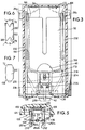
- Figure 1 is a longitudinal sectional view of a first embodiment of the present invention;
- Figure 1A is a bottom plan view of a check valve actuator from Figure 1 in a dispensing condition.
- Figure 2 is a longitudinal sectional view of a second embodiment of the present invention;
- Figure 3 is a sectional view taken generally along line III-III of Figure 2;
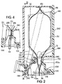
- Figure 4 is a partial sectional view from Figure 2 showing the actuator in a dispensing condition;
- Figure 5 is a sectional view taken generally along V-V of Figure 4;
- Figure 6 is a side elevational view of a pump tube shown in Figure 2;
- Figure 7 is a front elevational view of the pump tube of Figure 6;
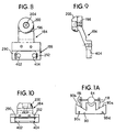
- Figure 8 is a front elevational view of a pump actuator shown in Figure 2;
- Figure 9 is a right side elevational view of the pump actuator of Figure 8; and
- Figure 10 is a bottom view of the pump actuator of Figure 8.
DETAILED DESCRIPTION
-
Referring to the figures, and specifically Figure 1 an embodiment of the liquid dispenser is illustrated. As illustrated the dispenser 10 includes a back plate 12 which typically is attached to a wall or other structure to support the dispenser 10 in a known way. The back plate 12 is effectively covered by a front cover 14 by suitable formations and/or screws.
-
The front cover 14 includes a window portion 16 therethrough. A push button 18 proceeds external of the front cover 14 through the window 16 and attaches to an actuating arm 24. The push button 18 is fixedly inserted into a socket 20 of the arm 24.
-
The actuating arm 24 is pivotably connected to the front cover 14, near its top at pin connectors 28a, 28b (see Figure 6). Inside the dispenser 10 between the front cover 14 and the back plate 12 is located an elongated conical trough 32 having a wide open top end 34, generally straight sides 36, a cone section 38 and a bottom opening 40. The trough 32 is supported in the dispenser by clips 44 attached to the back plate 12.
-
Placed within the trough 32 is a film pouch 48 having a sealed top end 50, a liquid containing volume or straight section 52, a generally conical section 58 below the straight section 52, and a cylindrical pathway 60 terminating in a narrow channel section 62 having an aperture 64 at its terminal end. Mounted within the cylindrical pathway 60 is a tube 70 having a sufficient thickness to retain a structural memory after collapsing. That is, the tube will spring back to its tubular shape after being compressed.
-
In an exemplary embodiment, the tube includes V-shaped notches 72 arranged laterally at a top end of the tube 60 and second V-shaped notches 76 arranged laterally at a bottom end of the tube. In Figure 1 the second V-shaped notches 76 are shown somewhat flattened, this due to a tightly formed and flattened cylindrical pathway 60 of the film pouch 48.
-
The actuator arm 24 provides at its low end an actuator 84. The actuator 84 provides at a top end thereof a hammer or impact portion 88 and a check valve actuator 90 at a lower end thereof. The back plate 12 extends inwardly at a lower portion thereof into a raised formation 96 which is generally box-shaped having an anvil formation 98 proceeding toward the cylindrical pathway 60 arranged in front thereof.
-
The formation 96 provides a bottom wall 102. A lower check valve 106 is attached to the bottom wall 102 via pins 108. The check valve comprises two pins 116, 118 which act as lever arms (see Figure 5). A spring 120 connects the pins 116, 118 at a base end thereof. The pins 116, 118 are pinned in a middle portion at pivot points 126, 128 respectively. The pins 116, 118 proceed from this middle portion through holes 136, 138 arranged in a nozzle portion of the film pouch.
-
The operation of the check valve actuator 90 is shown more clearly in Figure 1A. As the actuating arm 24 approaches the pouch 48 the pins 116, 118 make contact with and slide down the inclined surfaces 90a, 90b. The pins 116, 118 are thus drawn together to relax the aperture 64 of the pouch 48. Holes 90c, 90d are provided to pin the actuator 90 to the actuating arm or to the impact portion 88 or it can be formed integral therewith.
-
Figure 2 illustrates another embodiment of the dispenser 10 described with regard to Figure 1, referred to as dispenser 160. The trough 32 is supported within the dispenser 160 by a plurality of clips 166. A film pouch 170 is similar to the film pouch 48 except for a substantially shorter polymeric tube 172 located therein. In the embodiment shown in Figure 2, the tube 172 provides V-shaped notches 72 at a top end thereof and notches 178 at a bottom end thereof. In the embodiment shown in Figure 2, a front portion of the tube 172 has a shorter length than a rear portion 172b.
-
On a front side of the tube 172 mounted to the actuator arm 24 is an actuator 184. The actuator 184 provides a check valve actuator 188 arranged at a bottom end thereof and a hammer portion 196 at a top end thereof. The hammer portion 196 comprises a round compression member 200 bolted to the hammer portion 196 by bolt 204. The compression member 200 can be plastic, rubber or other material selected for hardness and compression (resiliency) to achieve an optimal squeezing effect against the tube 172. Because the compression member is bolted on, it can be readily changed depending on application. The actuator 184 is bolted to the actuator arm by bolts 206.
-
Figure 3 illustrates the pouch 170 mounted into the trough 32 having the wide opening 34 at a top end thereof and the smaller opening 40 at a bottom end thereof. The conical bottom section of the pouch 216 extends below the trough 34 and includes engaging holes 136, 138 for receipt of pins 116, 118 of the check valve.
-
A bolt 204 is used to secure a round compression member 200 to the hammer portion 196. Bolts 206, as illustrated, secure the actuator 184 to the actuating arm 24. The actuating arm 24 is shown as being of a generally U-shaped configuration with parallel actuating levers 230, 232 pinned above at the pins 28a, 28b.
-
The pouch 170 also comprises a tear-off portion 250. When portion 250 is torn off, aperture 64 is exposed.
-
Figure 4 illustrates the operation of the actuator when activated by a user. The round compression member 200 has pivoted with the actuating arm 24 to strike and close the tube 172 against a formation 260 formed on a back plate 262. In the illustrated embodiment, an anvil is not needed, and a flat area 266 is arranged on the formation 260. The compression member 200 squeezes the tube 172 to flatten the tube between its V-shaped notches 72 to close the tube off from the straight section 52 and conical section 58. Simultaneously the compression member 200 squeezes an amount of fluid residing in the tube downward out through the aperture 64. Also, in this condition, the check valve 106 is now engaged by the check valve actuator 184 to assist in holding the aperture 64 open by compressing the narrow channel 62 by moving the holes 136, 138 closer together.
-
Figure 5 illustrates the functioning of the check valve 106. The pins 116, 118 are shown extended through the holes 136, 138 in the narrow channel section 62 of the pouch. The pins have annular slots 262a, 262b to hold the narrow channel section 62 thereon. The pins have distal ends 280, 282 with surfaces 280a, 282a tapered outwardly.
-
Before the check valve actuator 184 makes contact with the pins 116, 118, a spring 120 causes the pins 116, 118 to pivot about their pivot points 126, 128 to spread apart from each other at their distal ends 280, 282. This places tension on the narrow channel section 62 of the pouch to hold the aperture 64 closed. When cammed surfaces 290, 292 of the check valve actuator 188 approach and impact the distal ends of the pins 280, 282 the sliding cam action on the tapered outside surfaces 280a, 282a of the distal ends 280, 282 causes the pins to move toward each other against the bias of the spring 120 to open up the aperture 64 as shown in dashed lines of Figure 5.
-
Figures 6 and 7 illustrate the tubular section 260 that is used in the present invention. V-shaped notches are formed both in the top section and the bottom section. In the preferred embodiment, the upper V-shaped notches 72 have an angle A = 60°. At a bottom end thereof an angle B is provided for the V-shaped notches.
-
As also illustrated in Figure 6 at a bottom end of the tube, a first arcuate side or "flap" 300 of the tube 172 is fashioned longer than a second arcuate side or "flap" 302 of the tube 172. The first arcuate side 300 can be arranged either on a side of the tube closest to the impacting hammer 196 (the front side) or on the side furthest away from the impacting hammer 196 (the back side). Depending on the orientation, different benefits are achieved.
-
One actuator of the system of the present invention has several features which achieve these inventive advantages. As the pump actuator arm is advanced in a predetermined arcuate motion in the performance of the dispensing function, the portion of the pump actuator arm at its upper end, described as the upper check valve actuator tip portion, progressively engages and compresses the upstream end of the pump tube against a "pump anvil" projection on the dispenser back molding. The progressive engagement involves slidably engaging the contoured surfaces of the anvil and the tip in a manner which utilizes the physical properties of the polymer that is used to mold the actuator (high memory, low set retention) and the contoured shapes of the two parts in a rolling, wedging effect, rather than a knife effect. Because of the engagement, a reduced resistance to the closing of the pump sleeve is achieved by the unique notching at the point of engagement with the tip and anvil.
-
Reduced resistance at the downstream end of the pump sleeve is also achieved by notching this end. By using a "V" notching and altering the length of the rear flap to increase length so that it is equal to that of the front flap, recovery and suck-back is increased along with back pressure and consequent operating force. By decreasing the rear flap length this results in decreased recovery and suck-back while also decreasing back pressure and consequent operating force.
-
Figures 8, 9 and 10 illustrate in more detail the actuator 184. The round compression member 200 is shown mounted to the hammer portion 196. The check valve actuator 188 is shown comprising caged surfaces 290, 292 and additionally shows receiving apertures 402, 404. The receiving apertures 402, 404 are provided for the lower check valve pins 116, 118 to be able to pass therethrough during the compression stroke of the actuator 184 against the pouch 170. The receiving apertures 402, 404 hold the pins 116, 118 together at a predetermined separation. The pins 116, 118 thereby will slide across the cammed surfaces 290, 292 and into the receiving apertures 402, 404.
-
It should be understood that Various changes and modifications to the presently preferred embodiments described herein will be apparent to those skilled in the art. Such changes and modifications can be made without departing from the spirit and scope of the present invention and without diminishing its attendant advantages. It is therefore intended that such changes and modifications be covered by the appended claims.