EP0787085B1 - Method of operating an anti-locking vehicle-brake system - Google Patents
Method of operating an anti-locking vehicle-brake system Download PDFInfo
- Publication number
- EP0787085B1 EP0787085B1 EP95935372A EP95935372A EP0787085B1 EP 0787085 B1 EP0787085 B1 EP 0787085B1 EP 95935372 A EP95935372 A EP 95935372A EP 95935372 A EP95935372 A EP 95935372A EP 0787085 B1 EP0787085 B1 EP 0787085B1
- Authority
- EP
- European Patent Office
- Prior art keywords
- brake
- vacuum
- driver
- pressure
- force booster
- Prior art date
- Legal status (The legal status is an assumption and is not a legal conclusion. Google has not performed a legal analysis and makes no representation as to the accuracy of the status listed.)
- Expired - Lifetime
Links
- 238000000034 method Methods 0.000 title claims abstract description 20
- 239000012530 fluid Substances 0.000 claims abstract description 3
- 230000001133 acceleration Effects 0.000 description 2
- 238000001514 detection method Methods 0.000 description 2
- 230000009286 beneficial effect Effects 0.000 description 1
- 238000010276 construction Methods 0.000 description 1
- 238000013016 damping Methods 0.000 description 1
- 238000012544 monitoring process Methods 0.000 description 1
- 238000009423 ventilation Methods 0.000 description 1
Images
Classifications
-
- B—PERFORMING OPERATIONS; TRANSPORTING
- B60—VEHICLES IN GENERAL
- B60T—VEHICLE BRAKE CONTROL SYSTEMS OR PARTS THEREOF; BRAKE CONTROL SYSTEMS OR PARTS THEREOF, IN GENERAL; ARRANGEMENT OF BRAKING ELEMENTS ON VEHICLES IN GENERAL; PORTABLE DEVICES FOR PREVENTING UNWANTED MOVEMENT OF VEHICLES; VEHICLE MODIFICATIONS TO FACILITATE COOLING OF BRAKES
- B60T8/00—Arrangements for adjusting wheel-braking force to meet varying vehicular or ground-surface conditions, e.g. limiting or varying distribution of braking force
- B60T8/32—Arrangements for adjusting wheel-braking force to meet varying vehicular or ground-surface conditions, e.g. limiting or varying distribution of braking force responsive to a speed condition, e.g. acceleration or deceleration
- B60T8/321—Arrangements for adjusting wheel-braking force to meet varying vehicular or ground-surface conditions, e.g. limiting or varying distribution of braking force responsive to a speed condition, e.g. acceleration or deceleration deceleration
- B60T8/3255—Systems in which the braking action is dependent on brake pedal data
- B60T8/326—Hydraulic systems
- B60T8/3265—Hydraulic systems with control of the booster
-
- B—PERFORMING OPERATIONS; TRANSPORTING
- B60—VEHICLES IN GENERAL
- B60T—VEHICLE BRAKE CONTROL SYSTEMS OR PARTS THEREOF; BRAKE CONTROL SYSTEMS OR PARTS THEREOF, IN GENERAL; ARRANGEMENT OF BRAKING ELEMENTS ON VEHICLES IN GENERAL; PORTABLE DEVICES FOR PREVENTING UNWANTED MOVEMENT OF VEHICLES; VEHICLE MODIFICATIONS TO FACILITATE COOLING OF BRAKES
- B60T13/00—Transmitting braking action from initiating means to ultimate brake actuator with power assistance or drive; Brake systems incorporating such transmitting means, e.g. air-pressure brake systems
- B60T13/10—Transmitting braking action from initiating means to ultimate brake actuator with power assistance or drive; Brake systems incorporating such transmitting means, e.g. air-pressure brake systems with fluid assistance, drive, or release
- B60T13/66—Electrical control in fluid-pressure brake systems
- B60T13/72—Electrical control in fluid-pressure brake systems in vacuum systems or vacuum booster units
-
- B—PERFORMING OPERATIONS; TRANSPORTING
- B60—VEHICLES IN GENERAL
- B60T—VEHICLE BRAKE CONTROL SYSTEMS OR PARTS THEREOF; BRAKE CONTROL SYSTEMS OR PARTS THEREOF, IN GENERAL; ARRANGEMENT OF BRAKING ELEMENTS ON VEHICLES IN GENERAL; PORTABLE DEVICES FOR PREVENTING UNWANTED MOVEMENT OF VEHICLES; VEHICLE MODIFICATIONS TO FACILITATE COOLING OF BRAKES
- B60T8/00—Arrangements for adjusting wheel-braking force to meet varying vehicular or ground-surface conditions, e.g. limiting or varying distribution of braking force
- B60T8/17—Using electrical or electronic regulation means to control braking
- B60T8/176—Brake regulation specially adapted to prevent excessive wheel slip during vehicle deceleration, e.g. ABS
- B60T8/1761—Brake regulation specially adapted to prevent excessive wheel slip during vehicle deceleration, e.g. ABS responsive to wheel or brake dynamics, e.g. wheel slip, wheel acceleration or rate of change of brake fluid pressure
- B60T8/17616—Microprocessor-based systems
-
- B—PERFORMING OPERATIONS; TRANSPORTING
- B60—VEHICLES IN GENERAL
- B60T—VEHICLE BRAKE CONTROL SYSTEMS OR PARTS THEREOF; BRAKE CONTROL SYSTEMS OR PARTS THEREOF, IN GENERAL; ARRANGEMENT OF BRAKING ELEMENTS ON VEHICLES IN GENERAL; PORTABLE DEVICES FOR PREVENTING UNWANTED MOVEMENT OF VEHICLES; VEHICLE MODIFICATIONS TO FACILITATE COOLING OF BRAKES
- B60T8/00—Arrangements for adjusting wheel-braking force to meet varying vehicular or ground-surface conditions, e.g. limiting or varying distribution of braking force
- B60T8/32—Arrangements for adjusting wheel-braking force to meet varying vehicular or ground-surface conditions, e.g. limiting or varying distribution of braking force responsive to a speed condition, e.g. acceleration or deceleration
- B60T8/321—Arrangements for adjusting wheel-braking force to meet varying vehicular or ground-surface conditions, e.g. limiting or varying distribution of braking force responsive to a speed condition, e.g. acceleration or deceleration deceleration
- B60T8/3255—Systems in which the braking action is dependent on brake pedal data
- B60T8/3275—Systems with a braking assistant function, i.e. automatic full braking initiation in dependence of brake pedal velocity
-
- B—PERFORMING OPERATIONS; TRANSPORTING
- B60—VEHICLES IN GENERAL
- B60T—VEHICLE BRAKE CONTROL SYSTEMS OR PARTS THEREOF; BRAKE CONTROL SYSTEMS OR PARTS THEREOF, IN GENERAL; ARRANGEMENT OF BRAKING ELEMENTS ON VEHICLES IN GENERAL; PORTABLE DEVICES FOR PREVENTING UNWANTED MOVEMENT OF VEHICLES; VEHICLE MODIFICATIONS TO FACILITATE COOLING OF BRAKES
- B60T8/00—Arrangements for adjusting wheel-braking force to meet varying vehicular or ground-surface conditions, e.g. limiting or varying distribution of braking force
- B60T8/32—Arrangements for adjusting wheel-braking force to meet varying vehicular or ground-surface conditions, e.g. limiting or varying distribution of braking force responsive to a speed condition, e.g. acceleration or deceleration
- B60T8/34—Arrangements for adjusting wheel-braking force to meet varying vehicular or ground-surface conditions, e.g. limiting or varying distribution of braking force responsive to a speed condition, e.g. acceleration or deceleration having a fluid pressure regulator responsive to a speed condition
- B60T8/48—Arrangements for adjusting wheel-braking force to meet varying vehicular or ground-surface conditions, e.g. limiting or varying distribution of braking force responsive to a speed condition, e.g. acceleration or deceleration having a fluid pressure regulator responsive to a speed condition connecting the brake actuator to an alternative or additional source of fluid pressure, e.g. traction control systems
- B60T8/4809—Traction control, stability control, using both the wheel brakes and other automatic braking systems
- B60T8/4827—Traction control, stability control, using both the wheel brakes and other automatic braking systems in hydraulic brake systems
- B60T8/4845—Traction control, stability control, using both the wheel brakes and other automatic braking systems in hydraulic brake systems using a booster or a master cylinder for traction control
- B60T8/4854—Traction control, stability control, using both the wheel brakes and other automatic braking systems in hydraulic brake systems using a booster or a master cylinder for traction control pneumatic boosters
-
- B—PERFORMING OPERATIONS; TRANSPORTING
- B60—VEHICLES IN GENERAL
- B60T—VEHICLE BRAKE CONTROL SYSTEMS OR PARTS THEREOF; BRAKE CONTROL SYSTEMS OR PARTS THEREOF, IN GENERAL; ARRANGEMENT OF BRAKING ELEMENTS ON VEHICLES IN GENERAL; PORTABLE DEVICES FOR PREVENTING UNWANTED MOVEMENT OF VEHICLES; VEHICLE MODIFICATIONS TO FACILITATE COOLING OF BRAKES
- B60T8/00—Arrangements for adjusting wheel-braking force to meet varying vehicular or ground-surface conditions, e.g. limiting or varying distribution of braking force
- B60T8/32—Arrangements for adjusting wheel-braking force to meet varying vehicular or ground-surface conditions, e.g. limiting or varying distribution of braking force responsive to a speed condition, e.g. acceleration or deceleration
- B60T8/34—Arrangements for adjusting wheel-braking force to meet varying vehicular or ground-surface conditions, e.g. limiting or varying distribution of braking force responsive to a speed condition, e.g. acceleration or deceleration having a fluid pressure regulator responsive to a speed condition
- B60T8/48—Arrangements for adjusting wheel-braking force to meet varying vehicular or ground-surface conditions, e.g. limiting or varying distribution of braking force responsive to a speed condition, e.g. acceleration or deceleration having a fluid pressure regulator responsive to a speed condition connecting the brake actuator to an alternative or additional source of fluid pressure, e.g. traction control systems
- B60T8/4809—Traction control, stability control, using both the wheel brakes and other automatic braking systems
- B60T8/4827—Traction control, stability control, using both the wheel brakes and other automatic braking systems in hydraulic brake systems
- B60T8/4863—Traction control, stability control, using both the wheel brakes and other automatic braking systems in hydraulic brake systems closed systems
- B60T8/4872—Traction control, stability control, using both the wheel brakes and other automatic braking systems in hydraulic brake systems closed systems pump-back systems
Definitions
- the invention relates to a method for operating a anti-lock motor vehicle brake system for driving stability and / or traction control.
- EP 0 581 105 A1 is a brake system with a vacuum brake booster known to the realization a traction control system with one independent of the driver's will controllable pneumatic 3/2-way valve cooperates, that to form a pneumatic pressure difference ventilation of the working chamber of the vacuum brake booster enables.
- the well-known Brake system an anti-lock control system (ABS), when braking for stable deceleration behavior of the vehicle.
- ABS anti-lock control system
- the publication mentioned are, however no specific information can be found as to which control logic for the one that is initiated by the driver Pedal actuation controllable vacuum booster the control concept for individual bikes, automatically controlled active braking, for example Purpose of a driving stability regulation, is based.
- the relative in the brake system described therein high consumption of vacuum volume during the traction control system or the unsecured one Vacuum availability to be regarded as disadvantageous.
- EP 0 581 105 A1 describes a method for operating an anti-lock device Motor vehicle brake system for traction control, which is independent of Pneumatic vacuum brake booster that can be operated by the driver brake pedal operated control valve and a vacuum brake booster Has downstream master cylinder, at the pressure chambers via a Return pumps and ABS hydraulic unit with low-pressure accumulator wheel brakes assigned to the individual vehicle wheels are connected, the vacuum brake booster when entering the traction control system is fully controlled regardless of the driver's will, and the desired Wheel brake pressures can be set using the ABS hydraulic unit.
- vacuum brake booster as the sole energy source for building up pressure Brake system described the hydraulic effort on the a standard ABS braking system.
- Indirect detection of the driver deceleration request is made in an advantageous development of the inventive method thereby ensuring that the actuation path one actuating the vacuum brake booster Brake pedal is determined, the brake pedal at a independent control of the driver Vacuum brake booster is not moved.
- the actuation path determined is preferably by means of a predetermined or learned during normal braking Characteristic curve in an actuating force or Vehicle deceleration setpoint converted. Through this Measures will be the use of inexpensive sensors enables.
- a precise determination of the driver deceleration request is according to a further advantageous feature allows the one initiated with the brake pedal Actuation force is sensed.
- the engine intervention is preferably carried out by means of the so-called e-gas.
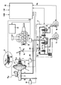
- the brake system shown in the drawing Implementation of the method according to the invention has two Brake circuits I and II on, their construction completely identical is, so the following description of a brake circuit the same applies to the other.
- the brake system shown consists essentially of a brake pressure sensor 1 to which via unspecified hydraulic lines Wheel brake cylinders 17, 18 can be connected, one between the brake pressure sensor 1 and the wheel brakes switched ABS hydraulic unit 2 and an electronic controller 25 with associated sensors.
- the assignment of the wheel brake cylinder 17.18 of the individual brake circuits I, II is such hit that the first wheel brake cylinder 17 either one Wheel of a vehicle axle and the other wheel brake cylinder 18 the diagonally opposite wheel of the other vehicle axle assigned (diagonal distribution of the brake circuits) or both wheel brake cylinders 17 and 18 of the same Vehicle axis are assigned (black and white division of the Brake circuits).
- the driver of the motor vehicle using a brake pedal 6 actuatable pressure transmitter 1 consists of a pneumatic brake booster 5, which is a master brake cylinder, preferably followed by a tandem master cylinder 3 is, the pressure rooms, not shown, with a Pressure medium reservoir 4 are connectable.
- a pneumatic brake booster 5 which is a master brake cylinder, preferably followed by a tandem master cylinder 3 is, the pressure rooms, not shown, with a Pressure medium reservoir 4 are connectable.
- actuating rod 7 To the Brake pedal 6 is coupled to an actuating rod 7 an actuation of a merely schematically indicated Control valve 8 made possible by the vehicle driver the build-up of a pneumatic differential pressure in the housing of the brake booster 5 controls.
- control signals of electronic controller 25 controllable electromagnet 26 enables external actuation of the control valve 8 also in superposition to one initiated on the brake pedal 6 Operating force.
- Brake light switch 14 One that is operatively connected to the brake pedal 6 Brake light switch 14 enables the detection of a Control of the brake booster 5 by the driver or by actuating the electromagnet 26. At External actuation of the brake booster 5 Brake pedal 6 carried and so the brake light switch 14th reversed. An operation initiated by the driver the brake booster 5 can, for. B. through use a release switch, not shown, can be recognized.
- the ABS hydraulic unit 2 has a motor-pump unit on that from an electric motor, not shown driven hydraulic return pump 13, whose suction side to a via a first check valve 9 the low-pressure accumulator 27 assigned to the wheel brakes 17, 18 connected. From the pressure side of the return pump 13 the pressure medium flows through a second check valve 10 and a damping chamber, not shown, into one hydraulic node 21. Connected to this both leading to the first wheel brake cylinder 17 Line section 19 and one to the second Wheel brake cylinder 18 leading line section 20. A hydraulic line 23 connects the pressure side of the Return pump 13 with the tandem master cylinder 3.
- Zur Modulation of the one controlled in the first wheel brake cylinder 17 Pressure serve a parallel connection of an inlet (11) with a third check valve 22 and an outlet valve 12, wherein - the mentioned parallel connection in the line section 19 is inserted and the outlet valve 12 for the purpose a wheel brake pressure reduction a connection between the first wheel brake cylinder 17 and the low pressure accumulator 27 enables.
- the controlled therein Being able to regulate hydraulic pressure is a second Parallel connection of a second inlet (15) with one fourth check valve 24 and a second outlet valve 16 provided, the parallel connection mentioned in Line section 20 is inserted and the exhaust valve 16th a connection for the purpose of reducing the wheel brake pressure between the second wheel brake cylinder 18 and the low pressure accumulator 27 manufactures.
- Sensing an am Brake pedal 6 actuation force initiated by the driver is preferably used with the brake pedal 6 articulated piston rod 7 interacting force sensor 28, the signals of which are fed to the controller 25.
- means are provided for detecting the master brake cylinder pressures, which are preferably formed by pressure sensors 32, 33 connected to the first and second brake circuits I, II, the output signals of which together with further signals, for example information are presented to the electronic controller 25 via the steering angle (LW), the wheel speeds ( ⁇ R ) and the vehicle reaction, such as, for example, the yaw rate (GWG) or the lateral acceleration ( ⁇ Q ).
- LW steering angle
- ⁇ R wheel speeds
- GWG yaw rate
- ⁇ Q lateral acceleration
- the electronic controller 25 receives the Signal line 31 information about the state of the Brake booster 5, for. B. the way of its moving Wall.
Landscapes
- Engineering & Computer Science (AREA)
- Transportation (AREA)
- Mechanical Engineering (AREA)
- Physics & Mathematics (AREA)
- Fluid Mechanics (AREA)
- Microelectronics & Electronic Packaging (AREA)
- Regulating Braking Force (AREA)
Abstract
Description
Die Erfindung betrifft ein Verfahren zum Betreiben einer blockiergeschützten Kraftfahrzeugbremsanlage zur Fahrstabilitäts- und/oder Antriebsschlupfregelung.The invention relates to a method for operating a anti-lock motor vehicle brake system for driving stability and / or traction control.
Aus der EP 0 581 105 A1 ist eine Bremsanlage mit einem Unterdruckbremskraftverstärker bekannt, der zur Realisierung einer Antriebsschlupfregelung mit einem unabhängig vom Fahrerwillen ansteuerbaren pneumatischen 3/2-Wegeventil zusammenwirkt, das zur Bildung einer pneumatischen Druckdifferenz eine Belüftung der Arbeitskammer des Unterdruckbremskraftverstärkers ermöglicht. Außerdem sieht die bekannte Bremsanlage ein Antiblockierregelsystem (ABS) vor, das bei einer Bremsung für stabiles Verzögerungsverhalten des Fahrzeuges sorgt. Der erwähnten Druckschrift sind jedoch keine konkreten Hinweise zu entnehmen, welche Ansteuerlogik für den unabhängig von einer durch den Fahrer ein-geleiteten Pedalbetätigung ansteuerbaren Unterdruckkraftverstärker dem Regelkonzept für radindividuelle, automatisch gesteuerte Aktivbremsvorgänge, beispielsweise zum Zweck einer Fahrstabilitätsregelung, zugrundeliegt. Außerdem sind bei der darin beschriebenen Bremsanlage der verhältnismäßige hohe Verbrauch von Unterdruckvolumen während der Antriebsschlupfregelung bzw. die nicht sichergestellte Unterdruckverfügbarkeit als nachteilig anzusehen.From EP 0 581 105 A1 is a brake system with a vacuum brake booster known to the realization a traction control system with one independent of the driver's will controllable pneumatic 3/2-way valve cooperates, that to form a pneumatic pressure difference ventilation of the working chamber of the vacuum brake booster enables. In addition, the well-known Brake system an anti-lock control system (ABS), when braking for stable deceleration behavior of the vehicle. The publication mentioned are, however no specific information can be found as to which control logic for the one that is initiated by the driver Pedal actuation controllable vacuum booster the control concept for individual bikes, automatically controlled active braking, for example Purpose of a driving stability regulation, is based. Furthermore are the relative in the brake system described therein high consumption of vacuum volume during the traction control system or the unsecured one Vacuum availability to be regarded as disadvantageous.
EP 0 581 105 A1 beschreibt ein Verfahren zum Betreiben einer blockiergeschützten Kraftfahrzeugbremsanlage zur Antriebsschlupfregelung, die einen unabhängig vom Fahrerwillen betätigbaren pneumatischen Unterdruckbremskraftverstärker mit bremspedalbetätigtem Steuerventil sowie einen dem Unterdruckbremskraftverstärker nachgeschalteten Hauptbremszylinder aufweist, an dessen Druckräume über ein Rückförderpumpen sowie Niederdruckspeicher aufweisendes ABS-Hydroaggregat den einzelnen Fahrzeugrädern zugeordnete Radbremsen angeschlossen sind, wobei beim Eintritt in die Antriebsschlupfregelung der Unterdruckbremskraftverstärker unabhängig vom Fahrerwillen voll ausgesteuert wird, und die gewünschten Radbremsdrücke mit Hilfe des ABS-Hydroaggregates eingestellt werden.EP 0 581 105 A1 describes a method for operating an anti-lock device Motor vehicle brake system for traction control, which is independent of Pneumatic vacuum brake booster that can be operated by the driver brake pedal operated control valve and a vacuum brake booster Has downstream master cylinder, at the pressure chambers via a Return pumps and ABS hydraulic unit with low-pressure accumulator wheel brakes assigned to the individual vehicle wheels are connected, the vacuum brake booster when entering the traction control system is fully controlled regardless of the driver's will, and the desired Wheel brake pressures can be set using the ABS hydraulic unit.
Es ist daher Aufgabe der vorliegenden Erfindung, ein Verfahren zum Betreiben einer blockiergeschützten Kraftfahrzeugbremsanlage zur Fahrstabilitäts- und/oder Antriebsschlupfregelung vorzuschlagen, das ein Minimieren des Verbrauchs von Unterdruckvolumen während der Fahrstabilitäts-und/oder Antriebsschlupfregelung ermöglicht.It is therefore an object of the present invention to provide a method to operate an anti-lock motor vehicle brake system for driving stability and / or traction control propose that minimizing consumption of negative pressure volume during driving stability and / or Traction control enables.
Diese Aufgabe wird erfindungsgemäß durch die im Patentanspruch 1 aufgeführten Merkmale gelöst. Dadurch wird erreicht, daß der nach dem Ausschalten der Fahrstabilitäts und/oder Antriebsschlupfregelung erfolgende Druckausgleich zwischen der Arbeits- und der Unterdruckkammer des Bremskraftverstärkers nur einen kleinen Verlust am Unterdruckvolumen bzw. Stellenergie bedeutet.This object is achieved by the claim 1 listed features solved. This ensures that that takes place after switching off the driving stability and / or traction control Pressure equalization between the working and the vacuum chamber of the brake booster only a small loss on the vacuum volume or actuating energy means.
Der Betrieb der beschriebenen Bremsanlage bei gleichzeitigem Vorliegen einer Betätigung durch den Fahrer und einer vom Fahrerwillen unabhängigen Ansteuerung des Unterdruckbremskraftverstärkers wird vorteilhaft dadurch ermöglicht, daß die Betätigung des Bremskraftverstärkers durch den Fahrer sensiert und die Fremdansteuerung entsprechend verändert wird. Durch diese Maßnahme wird erreicht, daß die Übertragung von Fahrer- und Fremdbremsung eine Softwaremaßnahme und daher entsprechend den Bedürfnissen der Fahrzeugregelung frei gestaltbar ist. The operation of the brake system described at the same time There is one operation by the driver and one independent control of the vacuum brake booster is advantageously made possible by that the actuation of the brake booster by the driver sensed and the external control changed accordingly becomes. This measure ensures that the Transfer of driver and external braking a software measure and therefore according to the needs of vehicle control can be freely designed.
Durch die Verwendung des Unterdruckbremskraftverstärkers als alleinige Energiequelle zum Druckaufbau wird in der beschriebenen Bremsanlage der Hydraulikaufwand auf den einer Standard-ABS-Bremsanlage beschränkt.By using the vacuum brake booster as the sole energy source for building up pressure Brake system described the hydraulic effort on the a standard ABS braking system.
Eine indirkte Erkennung des Fahrerverzögerungswunsches wird bei einer vorteilhaften Weiterbildung des Erfindungsverfahrens dadurch gewährleistet, daß der Betätigungsweg eines den Unterdruckbremskraftverstärker betätigenden Bremspedals ermittelt wird, wobei das Bremspedal bei einer vom Fahrerwillen unabhängigen Ansteuerung des Unterdruckbremskraftverstärkers nicht mitbewegt wird. Der ermittelte Betätigungsweg wird dabei vorzugsweise mittels einer vorbestimmten oder während Normalbremsungen erlernten Kennlinie in eine Betätigungskraft oder einen Fahrzeugverzögerungs-Sollwert umgerechnet. Durch diese Maßnahmen wird eine Verwendung kostengünstiger Sensorik ermöglicht.Indirect detection of the driver deceleration request is made in an advantageous development of the inventive method thereby ensuring that the actuation path one actuating the vacuum brake booster Brake pedal is determined, the brake pedal at a independent control of the driver Vacuum brake booster is not moved. Of the The actuation path determined is preferably by means of a predetermined or learned during normal braking Characteristic curve in an actuating force or Vehicle deceleration setpoint converted. Through this Measures will be the use of inexpensive sensors enables.
Eine genaue Ermittlung des Fahrerverzögerungswunsches wird nach einem weiteren vorteilhaften Merkmal dadurch ermöglicht, daß die mit dem Bremspedal eingeleitete Betätigungskraft sensiert wird.A precise determination of the driver deceleration request is according to a further advantageous feature allows the one initiated with the brake pedal Actuation force is sensed.
Um während der Regelung eine Bereitstellung eines zusätzlichen Unterdrucks zu gewährleisten, sieht eine vorteilhafte Weiterbildung des Erfindungsverfahrens vor, daß bei einem zu niedrigen Wert des in der Unterdruckkammer des Unterdruckbremskraftverstärkers herrschenden Unterdrucks eine Drosselung des Fahrzeugmotors vorgenommen wird. In order to provide a To ensure additional negative pressure sees one advantageous further development of the inventive method, that if the value in the vacuum chamber is too low of the vacuum brake booster prevailing Negative pressure throttled the vehicle engine becomes.
Der Motoreingriff erfolgt dabei vorzugsweise mittels des sogenannten E-Gases.The engine intervention is preferably carried out by means of the so-called e-gas.
Um ein Maß für den verfügbaren Unterdruck zu gewinnen, wird schließlich nach einem weiteren vorteilhaften Verfahrensmerkmal vorgesehen, daß der im Hauptbremszylinder eingesteuerte hydraulische Druck fortlaufend ermittelt wird. Durch diese Maßnahme wird eine zuverlässige Überwachung der Aussteuerung des Unterdruckbremskraftverstärkers ermöglicht.To get a measure of the available negative pressure, finally after another beneficial Process feature provided that in the master cylinder adjusted hydraulic pressure continuously determined becomes. This measure will make it reliable Monitoring the control of the vacuum brake booster enables.
Um dabei eine redundante Information über die Druckwerte zu erhalten, wird in einer vorteilhaften Weiterbildung die Druckermittlung mittels Drucksensoren durchgeführt, die an die Druckräume des Hauptzylinders angeschlossen sind.In order to provide redundant information about the pressure values is obtained in an advantageous development Pressure determination carried out by means of pressure sensors the pressure chambers of the master cylinder are connected.
Die Erfindung wird im nachfolgenden Text an einem Ausführungsbeispiel im Zusammenhang mit der beiliegenden Zeichnung näher erläutert.The invention is illustrated in the following text Embodiment in connection with the accompanying Drawing explained in more detail.
In der Zeichnung zeigt die einzige Figur eine Ausführung einer blockiergeschützten Kraftfahrzeugbremsanlage, mit der das erfindungsgemäße Verfahren realisiert werden kann.The only figure in the drawing shows an embodiment an anti-lock motor vehicle brake system with which the method according to the invention can be implemented.
Die in der Zeichnung dargestellte Bremsanlage zur
Durchführung des erfindungsgemäßen Verfahrens weist zwei
Bremskreise I und II auf, deren Aufbau völlig identisch
ist, so daß die folgende Beschreibung eines Bremskreises
ebenso auf den anderen zutrifft. Die gezeigte Bremsanlage
besteht im wesentlichen aus einem Bremsdruckgeber 1, an den
über nicht näher bezeichnete hydraulische Leitungen
Radbremszylinder 17,18 anschließbar sind, einem zwischen
dem Bremsdruckgeber 1 und den Radbremsen geschalteten
ABS-Hydroaggregat 2, sowie einem elektronischen Regler 25
mit zugehöriger Sensorik. Die Zuordnung der Radbremszylinder
17,18 der einzelnen Bremskreise I, II ist derart
getroffen, daß der erste Radbremszylinder 17 entweder einem
Rad einer Fahrzeugachse und der andere Radbremszylinder 18
dem diagonal gegenüberliegenden Rad der anderen Fahrzeugachse
zugeordnet ist (diagonale Aufteilung der Bremskreise)
oder aber beide Radbremszylinder 17 und 18 derselben
Fahrzeugachse zugeordnet sind (Schwarzweiß-Aufteilung der
Bremskreise).The brake system shown in the drawing
Implementation of the method according to the invention has two
Brake circuits I and II on, their construction completely identical
is, so the following description of a brake circuit
the same applies to the other. The brake system shown
consists essentially of a brake pressure sensor 1 to which
via unspecified hydraulic lines
Der vom Fahrer des Kraftfahrzeuges mittels eines Bremspedals
6 betätigbare Druckgeber 1 besteht aus einem
pneumatischen Bremskraftverstärker 5, dem ein Hauptbremszylinder,
vorzugsweise ein Tandemhauptzylinder 3 nachgeschaltet
ist, dessen nicht gezeigte Druckräume mit einem
Druckmittelvorratsbehälter 4 verbindbar sind. An das
Bremspedal 6 ist eine Betätigungsstange 7 angekoppelt, die
eine Betätigung eines lediglich schematisch angedeuteten
Steuerventils 8 durch den Fahrzeugfahrer ermöglicht, das
den Aufbau eines pneumatischen Differenzdruckes im Gehäuse
des Bremskraftverstärkers 5 steuert. Ein lediglich
schematisch dargestellter, durch Steuersignale des
elektronischen Reglers 25 ansteuerbarer Elektromagnet 26
ermöglicht dabei eine Fremdbetätigung des Steuerventils 8
auch in Überlagerung zu einer am Bremspedal 6 eingeleiteten
Betätigungskraft.The driver of the motor vehicle using a brake pedal
6 actuatable pressure transmitter 1 consists of a
Ein mit dem Bremspedal 6 in Wirkverbindung stehender
Bremslichtschalter 14 ermöglicht die Erkennung einer
Ansteuerung des Bremskraftverstärkers 5 durch den Fahrer
oder durch eine Betätigung des Elektromagneten 26. Bei
einer Fremdbetätigung des Bremskraftverstärkers 5 wird das
Bremspedal 6 mitgeführt und so der Bremslichtschalter 14
umgesteuert. Eine durch den Fahrer eingeleitete Betätigung
des Bremskraftverstärkers 5 kann z. B. durch den Einsatz
eines nicht gezeigten Löseschalters erkannt werden.One that is operatively connected to the brake pedal 6
Das ABS-Hydroaggregat 2 weist ein Motor-Pumpen-Aggregat
auf, das aus einer durch einen nicht gezeigten Elektromotor
angetriebenen hydraulischen Rückförderpumpe 13 besteht,
deren Saugseite über ein erstes Rückschlagventil 9 an einen
den Radbremsen 17,18, zugeordneten Niederdruckspeicher 27
angeschlossen ist. Von der Druckseite der Rückförderpumpe
13 strömt das Druckmittel über ein zweites Rückschlagventil
10 und eine nicht gezeigte Dämpfungskammer zu einem
hydraulischen Knotenpunkt 21. An diesen angeschlossen ist
sowohl ein zum ersten Radbremszylinder 17 führender
Leitungsabschnitt 19 als auch ein zum zweiten
Radbremszylinder 18 führender Leitungsabschnitt 20. Eine
hydraulische Leitung 23 verbindet die Druckseite der
Rückförderpumpe 13 mit dem Tandemhauptzylinder 3. Zur
Modulation des im ersten Radbremszylinder 17 eingesteuerten
Drucks dienen eine Parallelschaltung eines Einlaß- (11) mit
einem dritten Rückschlagventil 22 sowie ein Auslaßventil
12, wobei- die erwähnte Parallelschaltung im Leitungsabschnitt
19 eingefügt ist und das Auslaßventil 12 zum Zwecke
eines Radbremsdruckabbaus eine Verbindung zwischen dem
ersten Radbremszylinder 17 und dem Niederdruckspeicher 27
ermöglicht. Um in dem zum betrachteten Bremskreis
gehörenden zweiten Radbremszylinder 18 analog zum bereits
betrachteten Radbremszylinder 17 den darin eingesteuerten
hydraulischen Druck regulieren zu können, sind eine zweite
Parallelschaltung eines zweiten Einlaß- (15) mit einem
vierten Rückschlagventil 24 sowie ein zweites Auslaßventil
16 vorgesehen, wobei die erwähnte Parallelschaltung im
Leitungsabschnitt 20 eingefügt ist und das Auslaßventil 16
zum Zwecke eines Radbremsdruckabbaus eine Verbindung
zwischen dem zweiten Radbremszylinder 18 und dem Niederdruckspeicher
27 herstellt. Der Sensierung einer am
Bremspedal 6 durch den Fahrer eingeleiteten Betätigungskraft
dient ein vorzugsweise mit der am Bremspedal 6
angelenkten Kolbenstange 7 zusammenwirkender Kraftsensor
28, dessen Signale dem Regler 25 zugeführt werden.The ABS hydraulic unit 2 has a motor-pump unit
on that from an electric motor, not shown
driven hydraulic return pump 13,
whose suction side to a via a first check valve 9
the low-
Um schließlich vom Fahrer im Tandemhauptbremszylinder 3
eingeleitete Druckänderungen zu erkennen sind Mittel zur
Erfassung der Hauptbremszylinderdrücke vorgesehen, die
vorzugsweise durch an den ersten und den zweiten Bremskreis
I,II angeschlossene Drucksensoren 32, 33 gebildet sind,
deren Ausgangssignale zusammen mit weiteren Signalen, die
z.B. Informationen über den Lenkwinkel (LW), die Raddrehzahlen
(ωR), sowie die Fahrzeugreaktion, wie z.B. die Gierwinkelgeschwindigkeit
(GWG) oder die Querbeschleunigung
(αQ) darstellen, dem elektronischen Regler 25 zugeführt
werden.In order to finally recognize pressure changes introduced by the driver in the tandem
Außerdem erhält der elektronische Regler 25 über die
Signalleitung 31 Informationen über den Zustand des
Bremskraftverstärkers 5, z. B. den Weg seiner beweglichen
Wand.In addition, the
Bei einer Normalbremsung kann in den Radbremszylindern
17,18 sowohl ein Druckauf- als auch ein Druckabbau durch
entsprechende Betätigung des Bremsdruckgebers 1 über die
offenen Einlaßventile 11,15 erfolgen.With normal braking can in the
Bei einer ABS-Regelbremsung, bei der beispielsweise das der
Radbremse 17 zugeordnete Rad zu blockieren droht, wird die
Rückförderpumpe 13 gestartet. Die Druckmodulation erfolgt
durch entsprechendes Schalten des Ein- und des
Auslaßventils 11 und 12, wobei das in den Niederdruckspeicher
27 abgelassene Druckmittel mit der Rückförderpumpe
13 auf das Hauptbremszylinder-Druckniveau zurückgefördert
wird.With ABS standard braking, in which, for example, the
Beim Eintritt in jeden Fremdbremsvorgang wird der
Bremskraftverstärker 5 unabhängig vom Fahrerwillen mittels
Elektromagneten 26 voll ausgesteuert.When entering any external braking process, the
Brake
Mit den ABS-Ventilen 11,12,15,16 werden die benötigten
radindividuellen Bremsdruckwerte eingeregelt. Nicht
benötigtes Druckmittel wird von der Rückförderpumpe 13 in
den Hauptbremszylinder 3 zurückgefördert, wobei kein
Unterdruck verbraucht wird. Während der Fremdbremsung wird
ein möglicher Fahrerbremswunsch durch Erfassung der
Pedalbetätigung (Kraft und/oder Weg) und entsprechend
veränderte Fremdbremsdrücke berücksichtigt. Wenn sowohl
Fahrer- als auch Fremdbremsung beendet und alle Bremsdrücke
auf Null eingeregelt sind, hat die Rückförderpumpe 13 das
Unterdruckvolumen des Bremskraftverstärkers 5 wieder auf
den Wert gebracht, den es zu Beginn der Regelung hatte.
Unterdruckvolumen wird erst dann verbraucht, wenn die
Fremdbetätigung des Bremskraftverstärkers 5 ausgeschaltet
wird, und seine für die Fremdbremsung mit Atmosphärendruck
belüftete Arbeitskammer mit der Unterdruckkammer verbunden
wird, um den Bremskraftverstärker in die Lösestellung zu
bringen.With the
Dabei ist es besonders sinnvoll, wenn die Arbeitskammer des
Bremskraftverstärkers 5 in der Lösestellung ein möglichst
geringes Volumen aufweist. Dadurch wird erreicht, daß der
nach dem Ausschalten der Fremdansteuerung des Bremskraftverstärkers
5 erfolgte Druckausgleich zwischen Arbeits- und
Unterdruckkammer nur einen kleinen Verlust an Unterdruck
bedeutet, so daß noch genügend Unterdruck für eine weitere
Fremdbremsung oder eine Fahrerbremsung zur Verfügung steht.
Beginnt eine Fremdbremsung mit einem ungenügend
ausgebildeten Unterdruckniveau in der Unterdruckkammer des
Bremskraftverstärkers 5, so muß der elektromagnetische
Regler 25, zusammenwirkend mit einem Motorregler 30, eine
Drosselung des Fahrzeugmotors 29, beispielsweise per
E-Gas-Eingriff, vornehmen. Die Möglichkeit eines Eingriffs
in das Antriebsmanagement muß gegeben sein, damit die
Regelung bei Bedarf einen mit der vorliegenden
Fahrsituation unvereinbaren Fahrerbeschleunigungswunsch
korrigieren kann. It is particularly useful if the working chamber of the
Brake
- 11
- BremsdruckgeberBrake pressure sensor
- 22nd
- ABS-HydroaggregatABS hydraulic unit
- 33rd
- HauptbremszylinderMaster brake cylinder
- 44th
- DruckmittelvorratsbehälterPressure fluid reservoir
- 55
- BremskraftverstärkerBrake booster
- 66
- BremspedalBrake pedal
- 77
- BetätigungsstangeOperating rod
- 88th
- SteuerventilControl valve
- 99
- Rückschlagventilcheck valve
- 1010th
- Rückschlagventilcheck valve
- 1111
- EinlaßventilInlet valve
- 1212th
- AuslaßventilExhaust valve
- 1313
- RückförderpumpeReturn pump
- 1414
- BremslichtschalterBrake light switch
- 1515
- EinlaßventilInlet valve
- 1616
- AuslaßventilExhaust valve
- 1717th
- RadbremszylinderWheel brake cylinder
- 1818th
- RadbremszylinderWheel brake cylinder
- 1919th
- LeitungsabschnittLine section
- 2020th
- LeitungsabschnittLine section
- 2121
- KnotenpunktNode
- 2222
- Rückschlagventilcheck valve
- 2323
- Leitungmanagement
- 2424th
- Rückschlagventilcheck valve
- 2525th
- ReglerRegulator
- 2626
- ElektromagnetElectromagnet
- 2727
- NiederdruckspeicherLow pressure accumulator
- 2828
- KraftsensorForce sensor
- 2929
- FahrzeugmotorVehicle engine
- 3030th
- MotorregelschaltungMotor control circuit
- 3131
- SignalleitungSignal line
- 3232
- DrucksensorPressure sensor
- 3333
- DrucksensorPressure sensor
Claims (7)
- Method of operating an anti-lock automotive vehicle brake system for driving stability control and/or traction slip control which includes a pneumatic vacuum brake force booster (5), that is operable irrespective of the driver's wish, with a brake-pedal operated control valve (8) and a master brake cylinder (3) connected downstream of the vacuum brake force booster (5) and having its pressure chambers connected to wheel brakes (17, 18) associated with the individual vehicle wheels by way of an ABS hydraulic unit (2) including return pumps (13) and low-pressure accumulators (27), wherein, upon commencement of driving stability control and/or traction slip control, the vacuum brake force booster (5) has achieved its maximum attainable boosting force irrespective of the driver's wish, and the desired wheel braking pressures are adjusted by way of the ABS hydraulic unit (2), and, at the end of driving stability control and/or traction slip control, the actuation of the vacuum brake force booster (5) irrespective of the driver's wish will be deactivated only after the pressure fluid discharged from the wheel brakes (17, 18) to the low-pressure accumulators (27) has been returned to the master brake cylinder (3).
- Method as claimed in claim 1,
characterized in that the actuation of the control valve (8) of the vacuum brake force booster (5) by the driver is sensed. - Method as claimed in claim 2,
characterized in that the actuating travel of a brake pedal (6) which actuates the vacuum brake force booster (5) is determined, and the brake pedal (6) is not moved when the vacuum brake force booster (5) is actuated irrespective of the driver's wish. - Method as claimed in claim 3,
characterized in that the determined actuating travel is converted into an actuating force or a vehicle deceleration nominal value by way of a characteristic curve which is predefined or acquired during normal braking operations. - Method as claimed in claim 2,
characterized in that the actuating force which is introduced by the brake pedal (6) is sensed. - Method as claimed in any one of claims 1 to 5,
characterized in that the vehicle engine (29) is throttled when the value of the vacuum prevailing in the vacuum chamber of the vacuum brake force booster (5) is too low. - Method as claimed in claim 6,
characterized in that the hydraulic pressure introduced into the master brake cylinder (3) is continuously established.
Applications Claiming Priority (3)
| Application Number | Priority Date | Filing Date | Title |
|---|---|---|---|
| DE4438722 | 1994-10-29 | ||
| DE4438722A DE4438722A1 (en) | 1994-10-29 | 1994-10-29 | Method for operating an anti-lock motor vehicle brake system |
| PCT/EP1995/003779 WO1996013417A1 (en) | 1994-10-29 | 1995-09-23 | Method of operating an anti-locking vehicle-brake system |
Publications (2)
| Publication Number | Publication Date |
|---|---|
| EP0787085A1 EP0787085A1 (en) | 1997-08-06 |
| EP0787085B1 true EP0787085B1 (en) | 1999-09-01 |
Family
ID=6532032
Family Applications (1)
| Application Number | Title | Priority Date | Filing Date |
|---|---|---|---|
| EP95935372A Expired - Lifetime EP0787085B1 (en) | 1994-10-29 | 1995-09-23 | Method of operating an anti-locking vehicle-brake system |
Country Status (5)
| Country | Link |
|---|---|
| US (1) | US6019439A (en) |
| EP (1) | EP0787085B1 (en) |
| JP (1) | JPH10507718A (en) |
| DE (2) | DE4438722A1 (en) |
| WO (1) | WO1996013417A1 (en) |
Families Citing this family (7)
| Publication number | Priority date | Publication date | Assignee | Title |
|---|---|---|---|---|
| DE4438722A1 (en) * | 1994-10-29 | 1996-05-02 | Teves Gmbh Alfred | Method for operating an anti-lock motor vehicle brake system |
| DE19648596A1 (en) * | 1996-11-23 | 1998-05-28 | Teves Gmbh Alfred | Method for operating an anti-lock motor vehicle brake system |
| WO1999035018A1 (en) * | 1998-01-07 | 1999-07-15 | Continental Teves Ag & Co. Ohg | Travel dynamic control system and method for operating a travel dynamic control system |
| JPH11278234A (en) * | 1998-03-31 | 1999-10-12 | Tokico Ltd | Brake force control device |
| JP2001233194A (en) * | 2000-02-18 | 2001-08-28 | Aisin Seiki Co Ltd | Liquid pressure control device for vehicle |
| DE10338046B4 (en) * | 2003-08-19 | 2016-03-24 | Volkswagen Ag | Automotive braking system with an active brake booster and integrated ESP and / or EDS and / or ASR functionality |
| US10099670B2 (en) * | 2016-12-14 | 2018-10-16 | Robert Bosch Gmbh | Vehicle braking system and method |
Family Cites Families (14)
| Publication number | Priority date | Publication date | Assignee | Title |
|---|---|---|---|---|
| DE3739913A1 (en) * | 1987-11-25 | 1989-06-08 | Teves Gmbh Alfred | DEVICE FOR GENERATING A VACUUM |
| JPH03500279A (en) * | 1988-07-01 | 1991-01-24 | アルフレッド・テヴェス・ゲーエムベーハー | Brake unit with anti-lock device for automobiles |
| JP2678650B2 (en) * | 1989-02-13 | 1997-11-17 | 株式会社曙ブレーキ中央技術研究所 | Vacuum booster |
| DE3910285C2 (en) * | 1989-03-30 | 1996-12-19 | Teves Gmbh Alfred | Hydraulic brake system for motor vehicles with a device for regulating the drive slip |
| DE4004065A1 (en) * | 1990-02-10 | 1991-08-14 | Teves Gmbh Alfred | Vehicle anti-locking braking system - has piston position signal for servo device coupled to electronic control unit for magnetic braking regulation valves |
| DE4009640C1 (en) * | 1990-03-26 | 1991-06-06 | Mercedes-Benz Aktiengesellschaft, 7000 Stuttgart, De | |
| FR2667368B1 (en) * | 1990-09-28 | 1994-10-21 | Bendix Europ Services Tech | VACUUM SERVOMOTOR. |
| DE4102496A1 (en) * | 1991-01-29 | 1992-02-20 | Daimler Benz Ag | Brake pressure control unit for motor vehicle - couples pressures proportional to braking unit pedal force with ABS for dynamic stable behaviour |
| DE4208496C1 (en) * | 1992-03-17 | 1993-08-05 | Mercedes-Benz Aktiengesellschaft, 7000 Stuttgart, De | |
| JPH0680064A (en) * | 1992-07-13 | 1994-03-22 | Sumitomo Electric Ind Ltd | Fluid pressure control device |
| DE4234041C1 (en) * | 1992-10-09 | 1994-03-17 | Daimler Benz Ag | Brake pressure control device for a road vehicle |
| DE4238333C2 (en) * | 1992-11-13 | 2001-10-11 | Continental Teves Ag & Co Ohg | Vacuum brake booster |
| DE4329140C1 (en) * | 1993-08-30 | 1994-12-01 | Daimler Benz Ag | Brake pressure control device |
| DE4438722A1 (en) * | 1994-10-29 | 1996-05-02 | Teves Gmbh Alfred | Method for operating an anti-lock motor vehicle brake system |
-
1994
- 1994-10-29 DE DE4438722A patent/DE4438722A1/en not_active Withdrawn
-
1995
- 1995-09-23 WO PCT/EP1995/003779 patent/WO1996013417A1/en active IP Right Grant
- 1995-09-23 DE DE59506739T patent/DE59506739D1/en not_active Expired - Lifetime
- 1995-09-23 JP JP8514278A patent/JPH10507718A/en active Pending
- 1995-09-23 US US08/817,636 patent/US6019439A/en not_active Expired - Fee Related
- 1995-09-23 EP EP95935372A patent/EP0787085B1/en not_active Expired - Lifetime
Also Published As
| Publication number | Publication date |
|---|---|
| WO1996013417A1 (en) | 1996-05-09 |
| US6019439A (en) | 2000-02-01 |
| DE59506739D1 (en) | 1999-10-07 |
| DE4438722A1 (en) | 1996-05-02 |
| JPH10507718A (en) | 1998-07-28 |
| EP0787085A1 (en) | 1997-08-06 |
Similar Documents
| Publication | Publication Date | Title |
|---|---|---|
| EP0770012B1 (en) | Process for operating an anti-lock motor vehicle braking system | |
| EP0807039B1 (en) | Process for operating an antilocked motor vehicle braking system | |
| DE69737111T2 (en) | Automotive brake system | |
| EP0752939B1 (en) | Process for operating an electronically controlled brake actuating system | |
| DE10238278B4 (en) | Electronic brake system without pump unit | |
| EP0854808B1 (en) | Electronically controllable brake operating system | |
| DE69723207T2 (en) | Brake control system for vehicles | |
| DE102011076675A1 (en) | Method and device for controlling an electro-hydraulic brake system for motor vehicles | |
| EP0790908A1 (en) | Process for operating an anti-lock motor vehicle braking system | |
| DE4106336A1 (en) | HYDRAULIC BRAKE SYSTEM, ESPECIALLY FOR MOTOR VEHICLES | |
| EP2250056B1 (en) | Technology for the electronic brake force distribution in a vehicle brake system equipped with a hydraulic brake servo | |
| WO1993012960A1 (en) | Process for determining the adhesion/slip characteristic of the tyres of a road vehicle and slip regulation system for implementing the process | |
| DE19626926B4 (en) | Electronically controllable brake actuation system | |
| EP1023212B1 (en) | Method for improving the control performance of a motor vehicle control system | |
| WO2002042138A1 (en) | Method for controlling an electrohydraulic braking system | |
| EP2040967A1 (en) | A method for creating low pressure in a brake activation device of a motor vehicle brake system | |
| EP0722397B1 (en) | Brake system for motor vehicles | |
| EP0787085B1 (en) | Method of operating an anti-locking vehicle-brake system | |
| DE19706765C2 (en) | Hydraulic motor vehicle braking system | |
| DE19639387B4 (en) | Anti-skid control device | |
| DE19817190C1 (en) | Controlled-slip hydraulic braking system for road vehicles | |
| DE4300048A1 (en) | Method for determining the adhesion/slip characteristics of the tyres of a road vehicle | |
| DE10141616B4 (en) | Brake control device for a vehicle | |
| DE69833404T2 (en) | Manual rear brake control for an electro-hydraulic brake system | |
| DE4333568A1 (en) | Brake system for motor vehicles with a device for controlling both the brake slip and the traction slip |
Legal Events
| Date | Code | Title | Description |
|---|---|---|---|
| PUAI | Public reference made under article 153(3) epc to a published international application that has entered the european phase |
Free format text: ORIGINAL CODE: 0009012 |
|
| 17P | Request for examination filed |
Effective date: 19970530 |
|
| AK | Designated contracting states |
Kind code of ref document: A1 Designated state(s): DE FR GB |
|
| 17Q | First examination report despatched |
Effective date: 19980303 |
|
| GRAG | Despatch of communication of intention to grant |
Free format text: ORIGINAL CODE: EPIDOS AGRA |
|
| RAP1 | Party data changed (applicant data changed or rights of an application transferred) |
Owner name: CONTINENTAL TEVES AG & CO. OHG |
|
| GRAG | Despatch of communication of intention to grant |
Free format text: ORIGINAL CODE: EPIDOS AGRA |
|
| GRAH | Despatch of communication of intention to grant a patent |
Free format text: ORIGINAL CODE: EPIDOS IGRA |
|
| GRAH | Despatch of communication of intention to grant a patent |
Free format text: ORIGINAL CODE: EPIDOS IGRA |
|
| GRAA | (expected) grant |
Free format text: ORIGINAL CODE: 0009210 |
|
| AK | Designated contracting states |
Kind code of ref document: B1 Designated state(s): DE FR GB |
|
| REF | Corresponds to: |
Ref document number: 59506739 Country of ref document: DE Date of ref document: 19991007 |
|
| GBT | Gb: translation of ep patent filed (gb section 77(6)(a)/1977) |
Effective date: 19990927 |
|
| ET | Fr: translation filed | ||
| PLBE | No opposition filed within time limit |
Free format text: ORIGINAL CODE: 0009261 |
|
| STAA | Information on the status of an ep patent application or granted ep patent |
Free format text: STATUS: NO OPPOSITION FILED WITHIN TIME LIMIT |
|
| 26N | No opposition filed | ||
| REG | Reference to a national code |
Ref country code: GB Ref legal event code: IF02 |
|
| PGFP | Annual fee paid to national office [announced via postgrant information from national office to epo] |
Ref country code: GB Payment date: 20020829 Year of fee payment: 8 |
|
| PGFP | Annual fee paid to national office [announced via postgrant information from national office to epo] |
Ref country code: FR Payment date: 20020920 Year of fee payment: 8 |
|
| PG25 | Lapsed in a contracting state [announced via postgrant information from national office to epo] |
Ref country code: GB Free format text: LAPSE BECAUSE OF NON-PAYMENT OF DUE FEES Effective date: 20030923 |
|
| GBPC | Gb: european patent ceased through non-payment of renewal fee |
Effective date: 20030923 |
|
| PG25 | Lapsed in a contracting state [announced via postgrant information from national office to epo] |
Ref country code: FR Free format text: LAPSE BECAUSE OF NON-PAYMENT OF DUE FEES Effective date: 20040528 |
|
| REG | Reference to a national code |
Ref country code: FR Ref legal event code: ST |
|
| PGFP | Annual fee paid to national office [announced via postgrant information from national office to epo] |
Ref country code: DE Payment date: 20120930 Year of fee payment: 18 |
|
| REG | Reference to a national code |
Ref country code: DE Ref legal event code: R119 Ref document number: 59506739 Country of ref document: DE Effective date: 20140401 |
|
| PG25 | Lapsed in a contracting state [announced via postgrant information from national office to epo] |
Ref country code: DE Free format text: LAPSE BECAUSE OF NON-PAYMENT OF DUE FEES Effective date: 20140401 |