EP0786762B1 - Vector encoding method and encoder/decoder using the method - Google Patents
Vector encoding method and encoder/decoder using the method Download PDFInfo
- Publication number
- EP0786762B1 EP0786762B1 EP95932940A EP95932940A EP0786762B1 EP 0786762 B1 EP0786762 B1 EP 0786762B1 EP 95932940 A EP95932940 A EP 95932940A EP 95932940 A EP95932940 A EP 95932940A EP 0786762 B1 EP0786762 B1 EP 0786762B1
- Authority
- EP
- European Patent Office
- Prior art keywords
- vectors
- vector
- representative
- gain
- codebooks
- Prior art date
- Legal status (The legal status is an assumption and is not a legal conclusion. Google has not performed a legal analysis and makes no representation as to the accuracy of the status listed.)
- Expired - Lifetime
Links
- 239000013598 vector Substances 0.000 title claims description 697
- 238000000034 method Methods 0.000 title claims description 52
- 230000005284 excitation Effects 0.000 claims description 155
- 230000015572 biosynthetic process Effects 0.000 claims description 28
- 238000003786 synthesis reaction Methods 0.000 claims description 28
- 238000001228 spectrum Methods 0.000 claims description 18
- 239000011159 matrix material Substances 0.000 claims description 6
- 230000001419 dependent effect Effects 0.000 claims description 4
- 239000013256 coordination polymer Substances 0.000 description 8
- 238000010586 diagram Methods 0.000 description 8
- 238000004364 calculation method Methods 0.000 description 7
- 238000004891 communication Methods 0.000 description 3
- 238000007796 conventional method Methods 0.000 description 3
- 238000012545 processing Methods 0.000 description 3
- 238000013139 quantization Methods 0.000 description 3
- 230000003044 adaptive effect Effects 0.000 description 2
- 230000005540 biological transmission Effects 0.000 description 2
- 238000012935 Averaging Methods 0.000 description 1
- 230000005856 abnormality Effects 0.000 description 1
- 238000013459 approach Methods 0.000 description 1
- 230000000694 effects Effects 0.000 description 1
- 230000006870 function Effects 0.000 description 1
- 238000002372 labelling Methods 0.000 description 1
- 238000010295 mobile communication Methods 0.000 description 1
- 238000012986 modification Methods 0.000 description 1
- 230000004048 modification Effects 0.000 description 1
- 238000004904 shortening Methods 0.000 description 1
- 230000017105 transposition Effects 0.000 description 1
Images


Classifications
-
- H—ELECTRICITY
- H03—ELECTRONIC CIRCUITRY
- H03M—CODING; DECODING; CODE CONVERSION IN GENERAL
- H03M7/00—Conversion of a code where information is represented by a given sequence or number of digits to a code where the same, similar or subset of information is represented by a different sequence or number of digits
- H03M7/02—Conversion to or from weighted codes, i.e. the weight given to a digit depending on the position of the digit within the block or code word
-
- G—PHYSICS
- G06—COMPUTING; CALCULATING OR COUNTING
- G06T—IMAGE DATA PROCESSING OR GENERATION, IN GENERAL
- G06T9/00—Image coding
- G06T9/008—Vector quantisation
-
- G—PHYSICS
- G10—MUSICAL INSTRUMENTS; ACOUSTICS
- G10L—SPEECH ANALYSIS TECHNIQUES OR SPEECH SYNTHESIS; SPEECH RECOGNITION; SPEECH OR VOICE PROCESSING TECHNIQUES; SPEECH OR AUDIO CODING OR DECODING
- G10L19/00—Speech or audio signals analysis-synthesis techniques for redundancy reduction, e.g. in vocoders; Coding or decoding of speech or audio signals, using source filter models or psychoacoustic analysis
- G10L19/005—Correction of errors induced by the transmission channel, if related to the coding algorithm
-
- H—ELECTRICITY
- H03—ELECTRONIC CIRCUITRY
- H03M—CODING; DECODING; CODE CONVERSION IN GENERAL
- H03M7/00—Conversion of a code where information is represented by a given sequence or number of digits to a code where the same, similar or subset of information is represented by a different sequence or number of digits
- H03M7/30—Compression; Expansion; Suppression of unnecessary data, e.g. redundancy reduction
- H03M7/3082—Vector coding
-
- G—PHYSICS
- G10—MUSICAL INSTRUMENTS; ACOUSTICS
- G10L—SPEECH ANALYSIS TECHNIQUES OR SPEECH SYNTHESIS; SPEECH RECOGNITION; SPEECH OR VOICE PROCESSING TECHNIQUES; SPEECH OR AUDIO CODING OR DECODING
- G10L19/00—Speech or audio signals analysis-synthesis techniques for redundancy reduction, e.g. in vocoders; Coding or decoding of speech or audio signals, using source filter models or psychoacoustic analysis
- G10L2019/0001—Codebooks
- G10L2019/0004—Design or structure of the codebook
- G10L2019/0005—Multi-stage vector quantisation
-
- G—PHYSICS
- G10—MUSICAL INSTRUMENTS; ACOUSTICS
- G10L—SPEECH ANALYSIS TECHNIQUES OR SPEECH SYNTHESIS; SPEECH RECOGNITION; SPEECH OR VOICE PROCESSING TECHNIQUES; SPEECH OR AUDIO CODING OR DECODING
- G10L19/00—Speech or audio signals analysis-synthesis techniques for redundancy reduction, e.g. in vocoders; Coding or decoding of speech or audio signals, using source filter models or psychoacoustic analysis
- G10L2019/0001—Codebooks
- G10L2019/0013—Codebook search algorithms
- G10L2019/0014—Selection criteria for distances
Definitions
- the multipliers 21 and 22 in Fig. 2A may be omitted by prestoring, as the representative vectors, weighted representative vectors w 1 z 1i and w 2 z 2j obtained by multiplying the representative vectors in the codebooks CB1 and CB2 by the weighting coefficient vectors w 1 and w 2 .
- the multipliers 24 and 25 in Fig. 2B may be omitted by prestoring the weighted representative vectors w 1 z 1i and w 2 z 2j in the codebooks CB3 and CB4, respectively.
- the multipliers 21 and 22 may be omitted by prestoring weighted gain vectors in the gain codebooks CB1 and CB2. In Figs.
Landscapes
- Engineering & Computer Science (AREA)
- Theoretical Computer Science (AREA)
- Multimedia (AREA)
- Physics & Mathematics (AREA)
- Computational Linguistics (AREA)
- Signal Processing (AREA)
- Health & Medical Sciences (AREA)
- Audiology, Speech & Language Pathology (AREA)
- Human Computer Interaction (AREA)
- Acoustics & Sound (AREA)
- General Physics & Mathematics (AREA)
- Compression, Expansion, Code Conversion, And Decoders (AREA)
Description
- The present invention relates to a vector coding method that is used to encode speech, images and various other pieces of information and is particularly suited to encoding of information that is transmitted over an error-prone channel such as a mobile radio channel and encodes an input vector through the use of a plurality of codebooks each composed of plural representative vectors. The invention also pertains to a vector encoder using the above-mentioned vector coding method and a vector decoder for decoding codes encoded by the vector encoder.
- Methods that have been proposed to transmit vectors over channels prone to channel errors are to set representative vectors in anticipation of possible channel errors and to take into account the channel errors when labeling representative vectors. These methods are disclosed in Kumazawa, Kasahara and Namekawa, "A Communication of Vector Quantizers for Noisy Channels," Transactions of the Institute of Electronics, Information and Communication Engineers of Japan, Vol. J67-B, No. 1, pp. 1-8,1984, Zeger and Gersho, "Pseudo-Gray Coding," IEEE Trans. on Comm., Vol. 38, No. 12, pp. 2147-2158, 1990, and other literature. These methods hold all representative vectors directly in one codebook, and hence require large storage capacity for storing the codebook.
- As a method that does not need large storage capacity in transmitting vectors over channels prone to channel errors, there has been proposed to transmit vectors after quantizing them through the use of two structured codebooks. This is disclosed in Moriya, "Two-Channel Vector Quantizer Applied to Speech coding," Transactions of the Institute of Electronics, Information and Communication Engineers of Japan, IT87-106, pp. 25-30, 1987 and other literature. This method has two small-scale codebooks and uses two representative vectors in combination to reduce the storage capacity needed and transmits two labels indicative of the two representative vectors to lessen the influence of channel errors. This method will be described with reference to Figs. 1A and 1B. The representative vectors of the codebooks are generated beforehand by learning, for instance. In an encoder depicted in Fig. 1A, one representative vector z1i is fetched from a codebook CB1 and one representative vector z2j from a codebook CB2, then they are added together in a vector combining part 3 to generate a vector sum yij=z1i +z2j, and the distance, d(X,yij), between the combined representative vector y ij and an input vector X via an input terminal 4 is calculated, as distortion, in a distance calculating part 5. A control part 6 controls representative vector select switches 7 and 8 for the codebooks CB1 and CB2 and searches them for the representative vectors z1i and z2j that minimize the output d(X,y ij) from the distance calculating part 5. The control part 6 provides, as an encoded output to an output terminal 9, labels i and j of the representative vectors z 1i and z 2j that provide minimum distance.
- In a decoder shown in Fig. 1B, the control part 12 controls representative vector select switches 13 and 14 in accordance with the labels i and j in the input code applied via an input terminal 11 and reads out representative vectors z1i and z2j from codebooks CB3 and CB4, respectively. The thus read-out representative vectors z1i and z2j are combined in a vector combining part 17 into a reconstructed vector y ij=z 1i+z 2j, which is provided to an output terminal 18. Incidentally, the codebooks CB3 and CB4 are identical with those CB1 and CB2, respectively.
- The method described above in respect of Figs. 1A and 1B saves storage capacity of the codebooks for storing the representative vectors and lessens the influence of channel errors by combining the vectors in the decoder through utilization of the two labels corresponding thereto.
- A problem of this method is that the amount of processing required is very large because it involves the calculation of the distance d(X,y ij) for every combination of representative vectors of the two codebooks in search for the pair of representative vectors that minimizes the distance.
- TOMOYUKI OHYA et al. in "Revised TC-WVQ speech coder for mobile communication system", Proc. of the Int. Conf. on Spoken Language Processing (ICSLP), Kobe, November. 18-22, 1990, vol. 1, pp. 125-128, ACOUSTIC SOCIETY OF JAPAN, disclose a method according to the pre-characterizing portion of claim 1 and an encoder (decoder) according to the pre-characterizing portion of claim 14 (22). In this prior art, a subgroup of representative vectors is taken from each codebook. Each vector from a respective subgroup is multiplied by a respective sign vector whose components are either +1 or -1. The combined vector is then multiplied with a gain. More particularly, all odd components of the combined vector are multiplied with a first gain factor and all even components of that combined vector are multiplied with a second gain factor to obtain a weighted combined vector.
- With these methods, however, if an error arises in the labels during transmission over the channel, then distortion will occur in all elements of the received vector. According to the circumstances, the error will cause an abnormally large amount of distortion in the decoded output.
- An object of the present invention is to provide a vector coding method that prevents an error in the input code to the decoder from causing serious distortion of its output.
- Another object of the present invention is to provide a vector coding method that prevents an error in the input code to the decoder from causing serious distortion of its output and permits reduction of the amount of processing required.
- Another object of the present invention is to provide a vector encoder that embodies the above-mentioned vector coding method.
- Still another object of the present invention is to provide a vector decoder that decodes a vector encoded by the vector coding method that serves the above-mentioned objects.
- These objects are achieved with a method as claimed in claims 1 to 4, an encoder as claimed in claims 16, 18, 20 and 22, and a decoder as claimed in claims 25 and 27, respectively. Preferred embodiments of the invention are subject-matter of the dependent claims.
-
- Fig. 1A is a block diagram showing the configuration of an encoder embodying a conventional vector coding method;
- Fig. 1B is a block diagram showing a conventional decoder for use with the encoder of Fig. 1A;
- Fig. 2A is a block diagram illustrating an example of the encoder embodying the present invention;
- Fig. 2B is a block diagram illustrating an embodiment of the decoder according to the present invention;
- Fig. 3A is a graph showing each representative vector z1i of a codebook CB1;
- Fig. 3B is a graph showing a vector obtained by multiplying each representative vector z1i by a weighting coefficient vector w 1;
- Fig. 3C is a graph showing each representative vector z 2j of a codebook CB2;
- Fig. 3D is a graph showing a vector obtained by multiplying each representative vector z 2j by a weighting coefficient vector w 2;
- Fig. 3E is a graph showing examples of a combined vector and an erroneous combined vector in the present invention;
- Fig. 3F is a graph showing examples of a combined vector and an erroneous combined vector in the prior art;
- Fig. 4 is a graph showing a set of weighted representative vectors and a straight line for approximation, for explaining the vector coding method of the present invention;
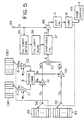
- Fig. 5 is a block diagram illustrating an example of the encoder of the present invention applied to the CELP scheme;
- Fig. 6A is a table showing a first codebook with weighted gain vectors stored therein;
- Fig. 6B is a table showing a second codebook with weighted gain vector stored therein;
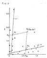
- Fig. 7 is a graph showing weighted gain vectors of Figs. 6A and 6B on a coordinate system;
- Fig. 8 is a block diagram illustrating the encoder of the present invention applied to the quantization of random excitation vectors;
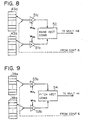
- Fig. 9 is a block diagram illustrating the encoder of the present invention applied to the quantization of pitch excitation vectors;
- Fig. 10 is a block diagram illustrating the encoder of the present invention applied to the VSELP scheme;
- Fig. 11 is a graph showing segmental SN ratio of reconstructed speech with respect to a channel error rate in the cases of using one gain codebook and two gain codebooks for vector encoding of gains gp and gc in Fig. 5;
- Fig. 12 is a graph showing, as an equivalent Q value, the MOS of the reconstructed speech with respect to the channel error rate in the two cases of Fig. 11; and
- Fig. 13 is a graph showing the segmental SN ratio of reconstructed speech with respect to the channel-error rate in the case of the present invention that uses two weighted gain codebooks for vector encoding of the gains gp and gc in Fig. 5.
-
- In Figs. 2A and 2B there is illustrated in block form an embodiment of the present invention, in which the parts corresponding to those in Figs. 1A and 1B are identified by the same reference numerals. In the encoder of Fig. 2A, multipliers 21 and 22 are provided between the representative selection switches 7, 8 and the vector combining part 3, by which components of L-dimensional (where L is an integer equal to or greater than 2) representative vectors z 1i=(z1i1, z1i2, ..., z1iL) and z 2j=(z2j1, z2j2, ..., z2jL) selected from the codebooks CB1 and CB2 are multiplied by the corresponding components of L-dimensional weighting coefficient vectors w 1=(w11, w12, ..., w1L) and w 2=(w21, w22, ..., w2L), respectively. One of the L components forming each of the weighting coefficient vectors w 1 and w 2 is larger than the others and the positions of these maximum components in the respective weighting coefficient vectors w 1 and w 2 differ with the codebooks CB1 and CB2. According to the present invention, letting the weighting coefficient vectors w 1 and w 2 be represented by the following weighting coefficient matrixes W1 and W2 that have, as diagonal elements, the values w11, w12, ..., w1L of the components by which the respective components of the representative vectors are multiplied:the weighting coefficient vectors w 1 and w 2 may preferably be selected so that the sum of the weighting coefficient matrixes W1 and W2 of the codebooks CB1 and CB2 becomes a constant multiple of the unit matrix as follows:
 where K is a predetermined constant. Vectors w 1 z 1i and w 2 z 2j, obtained by multiplying the representative vectors z 1i and z 2j by the weighting coefficient vectors w 1 and w 2, respectively, are combined in the vector combining part 3, and the codebooks CB1 and CB2 are searched for representative vectors z 1i and z 2j that minimize the distance between the combined vector y ij and the input vector X.
- With such a configuration as described above, for example, when L=2, the representative vectors z 1i and z 2j are expressed by two-dimensional vectors z 1i=(z1i1,z1i2) and z 2j=(z2j1,z2j2), respectively. Suppose that k=2 and that the weighting coefficients which satisfy Eq. (3) are w 1=(w11=1.8, w12=0.2) and w 2=(w21=0.2, w22=1.8). Assuming that representative vectors z 11, z 12, ... of the codebook CB1 are distributed substantially uniformly all over a plane of a certain two-dimensional range defined by z 1i1 in the first-dimensional direction and z 1i2 in the second-dimensional direction as shown in Fig. 3A, weighted representative vectors z 11' and z 12', ..., obtained by multiplying each representative vector z 1i=(z1i1, z1i2) by the weighting coefficient vector w 1=(1.8, 0.2), are concentrated close to the first-dimensional axis as shown in Fig. 3B. Similarly, assuming that representative vectors z 21, z 22, ... of the codebook CB2 are distributed substantially uniformly all over the plane of a certain two-dimensional range defined by two axes as depicted in Fig. 3C, weighted representative vectors, obtained by multiplying the representative vectors z 21, z 22, ... by the weighting coefficient vectors w 2=(0.2, 1.8), are concentrated close to the second-dimensional axis as shown in Fig. 3D.
- Suppose, for example, that when it is judged at the transmitting side that the weighted combined vector y ij of the representative vectors z 2j and z 1i has the minimum distortion with respect to the input signal X, the label of the one weighted representative vector z 1i becomes z 1i' because of a channel error as shown in Fig. 3E. In this instance, the combined vector y ij changes to y ij' at the receiving side. There is a possibility that the weighted representative vector z 1i changes to any other weighted representative vectors z 1i', but since the vector z 1i has a biased distribution, the value of the second-dimensional component of an error vector, Δy=Δy ij-y ij', between the combined vectors y ij and y ij' is relatively small, no matter how much the vector z 1i may change. In contrast to this, in the case where the combined vector is not multiplied by the weighting coefficient, if the one representative vector z 1i changes to a representative vector z 1i', combined vectors of these vectors z 1i and z 1i' and the other representative vector z 2j become y ij and y ij', respectively, as shown in Fig. 3F. Since there is a likelihood of the representative vector z 1i changing to any of the representative vectors of the codebook CB1 and since the representative vectors z 11, z 12, ... are distributed over a wide range, the error vector Δy between the combined vector y ij and the changed combined vector y ij' is likely to have appreciably large first- and second-dimensional components.
- In other words, in the example of Fig. 3E, when the weighted representative vector w 1 z 1i=(w11z1i1, w12z1i2) becomes w 1 z 1i'=(w11z1i1', w12z1i1') because of a channel error, distortion is concentrated on the first-dimensional component w11z1i1' to keep down distortion of the second-dimensional component w12z1i2', by which distortion is reduced as a whole.
- Fig. 2B illustrates in block form an embodiment of the decoder of the present invention, which is supplied with the labels i and j and the weighting coefficient vectors w 1 and w 2 from the encoder of Fig. 2A and decodes the code y ij. The decoder has the same codebooks CB3 and CB4 as those CB1 and CB2 in Fig. 2A, reads out representative vectors of the labels i and j of the inputted code from the codebooks CB3 and CB4 and combines them as is the case with Fig. 113. In this embodiment, multipliers 24 and 25 are provided between the switches 13, 14 and the vector combining part 17, by which representative vectors z 1i and z 2j read out of the codebooks CB3 and CB4 are multiplied by the same weighting coefficient vectors w 1 and w 2 as those used by the corresponding multipliers 21 and 22 of the Fig. 2A encoder. The thus multiplied representative vectors w 1 z 1i and w 2 z 2j are combined in the vector combining part 17 into the reconstructed vector y ij. As will be evident from the above, it is also possible to omit the multipliers 21, 22, 24 and 25 by prestoring in the codebooks CB1, CB3 and CB2, CB4 in Figs. 2A and 2B weighted representative vectors obtained by multiplying the representative vectors z 1i and z 2j by the weighting coefficient vectors w 1 and w 2, respectively.
- In the encoder of Fig. 2A, the combined vector y ij is determined for every combination of representative vectors z 1i and z 2j prestored in the codebooks CB1 and CB2, then the distortion of each combined vector is calculated with respect to the input signal vector X, and a decision is made of which pair of representative vectors z 1i and z 2j provides the minimum distortion. With this method, however, the number of calculations increases sharply as the codebooks CB1 and CB2 increase in size. Next, a description will be given of a scheme which pre-selects small numbers of representative vectors z 1i and z 2j and determines the pair of representative vectors of the minimum distortion among them, thereby reducing the computational complexity and hence shortening the operation time.
- Let it be assumed, for example, that the codebooks CB1 and CB2 in Fig. 2A have 8 and 16 representative vectors, respectively, and that the vectors z 1i and z 2j are all two-dimensional. In Fig. 4, eight weighted representative vectors, obtained by multiplying the eight representative vectors z 1i of the codebook CB1 by the weighting coefficient vector w 1=(w11=1.8, w12=0.2), are indicated by crosses; 16 weighted representative vectors, similarly obtained by multiplying the 16 representative vectors z 2j of the codebook CB2 by the weighting coefficient vectors w 2=(w21=0.2, w22=1.8), are indicated by white circles. The input signal vector is indicated by X, which is composed of a predetermined number of signal samples of each frame, two samples in this example.
- The two-dimensional weighting coefficient vectors w 1 and w 2 for the two-dimensional vectors z 1i and z 2j are determined such that they satisfy Eq. (3); w11+w21=w12+w22=2 in this example. As depicted in Fig. 4, the weighted representative vectors marked with the white circles and the weighted representative vectors marked with the crosses are distributed separately on the sides opposite with respect to a straight line of a 45°-gradient and passing through the origin (0, 0). The following description will be given on the assumption that there are stored such weighted representative vectors in the codebooks CB1 and CB2 in Fig. 2A and in the CB3 and CB4 in Fig. 2B, with the multipliers 21, 22, 24 and 25 left out.
- With this scheme, the set of weighted representative vectors (indicated by the crosses) of the codebook CB1 is approximated with a straight line 27. That is, the straight line 27 is determined so that the sum of distances, D11, D12, ..., D18, between it and the respective crosses (or distances in the second-dimensional axis direction) is minimum. Likewise, the set of weighted representative vectors (indicated by the white circles) of the codebook CB2 is approximated with a straight line 28. The straight line 28 is also determined so that the sum of distances, D21, D22, ..., D216, between it and the respective white circles (or distances in the first-dimensional axis direction) is minimum.
- The input vector X is projected on the approximating straight lines 27 and 28 and pluralities of weighted representative vectors present around the projections are selected. That is, a calculation is made of the value on the abscissa and hence a first-dimensional value p1x at the intersection P1 of a straight line 29 passing through the input signal vector X and parallel to the approximating straight line 28 and the approximating straight line 27, then the value P1x and first-dimensional values (values of first components) of the cross-marked weighted representative vectors having a wide first-dimensional distribution are compared, and a predetermined number of, for example, three, weighted representative vectors are selected, as a subgroup H1, in increasing order of the difference between the value p1x and the first-dimensional value of the respective weighted representative vector. In this way, the weighted representative vectors are pre-selected for the codebook CB1. Similarly, a calculation is made of a value on the ordinate and hence a second-dimensional value p2y at the intersection P2 of a straight line 31 passing through the input signal vector X and parallel to the approximating straight line 27 and the approximating straight line 28, then the second-dimensional value p2y and second-dimensional values (values of second components) of the white-circled weighted representative vectors having a wide second-dimensional distribution, and a predetermined number of, for example, three, weighted representative vectors are selected, as a subgroup H2, in the order of increasing differences between the value p2y and the second-dimensional values of the weighted representative vectors. This is the pre-selection of the weighted representative vectors for the codebook CB2.
- Only the weighted representative vectors thus pre-selected from the codebooks CB1 and CB2 are searched for a pair of weighted representative vectors that provides the minimum distance between their combined vector and the input signal vector. In this example, since three weighted representative vectors are pre-selected from each of the codebooks CB1 and CB2, the number of their combinations is nine, and hence the number of combined vectors is nine. When the pre-selection scheme is not adopted, the number of combinations of the weighted representative vectors (the number of combined representative vectors) is 8×16=128, and when the pre-selection is made, the number of calculations for the distance to the input signal vector X is reduced down to 9/128 of the number of calculations needed when no pre-selection takes place. In this pre-selection scheme, when M codebooks are used, the number of dimensions of representative vectors is also set to M. The M weighting coefficient vectors each have at least one maximum component at a different component position (that is, in a different dimension), and by multiplying the representative vector by the weighting coefficient vector, that dimension is emphasized more than the other dimensions.
- Fig. 5 illustrates an embodiment of the coding method of the present invention applied to speech coding of the CELP (Code-Excited Linear Prediction Coding) system. In the CELP system, as disclosed by M.R. Schroeder and B.S. Atal in "Code-Excited Linear Prediction (CELP): High-Quality Speech at Very Low Bit Rates", Proc. ICASSP'85, pp. 937-940, 1985, for instance, pitch excitation vectors read out of a pitch excitation source codebook and random excitation vectors read out of a random excitation source codebook are respectively provided with gains and are combined in pairs, then the combined vectors are each fed as an excitation signal to a synthesis filter to obtain synthesized speech, then two vectors and two gains therefor are determined which minimize distortion of the synthesized speech with respect to input speech, and labels of these vectors and labels of the gains are outputted as encoded results of the input speech, together with the filter coefficients of the synthesis filter. By applying the vector coding method of the present invention to the encoding of the gains for the two vectors in the CELP system, it is possible to prevent the occurrence of gross distortion in the decoded or reconstructed speech by a channel error in the codes representing the gains.
- The input speech signal X fed via an input terminal 34 is sampled with a fixed period and is expressed as a vector that is provided as a sequence of digital sample values for each frame period. The input signal vector X of every frame is subjected to, for example, an LPC analysis in a filter-coefficient determining part 35, from which linear predictive coefficients are provided. The linear predictive coefficients are used to calculate a spectrum envelope parameter, which is quantized in a filter coefficient quantizing part 36, and the quantized value is set as the filter coefficient of a synthesis filter 37. In a pitch excitation source codebook 39 there are stored sequences of sample values of waveforms respectively containing different pitch period components and labeled as pitch excitation vectors. In a random-excitation source codebook 43 there are stored sequences of sample values of various random waveforms respectively labeled as random-excitation vectors. The pitch-excitation vectors and the random-excitation vectors stored in the pitch-excitation source codebook 39 and the random-excitation source codebook 43 are each composed of components of the same number as that of samples of one frame. A selection switch 38 is controlled by the control part 6 to select one of the pitch-excitation vectors in the pitch-excitation source codebook 39, and the selected pitch-excitation vector is multiplied by a given gain in a gain providing part 41, thereafter being applied to the synthesis filter 37. The difference between synthesized speech Xp from the synthesis filter 37 and the input speech signal X is calculated by a subtractor 48, and in the distortion calculating part 5 the difference is used to calculate distortion D as D=∥X-Xp∥2. Similarly, the other pitch-excitation vectors are sequentially taken out from the pitch-excitation source codebook 39 via the switch 38 under the control of the control part 6, then the above-mentioned distortion is calculated for each pitch-excitation vector, and the pitch-excitation vector of the minimum distortion is determined. Next, one of the random-excitation vectors stored in the random-excitation source codebook 43 is taken out through a switch 42 and amplified by a given gain in a gain providing part 46, thereafter being fed to an adder 47 wherein it is combined to the already determined pitch-excitation vector into an excitation signal vector E. The excitation signal vector E is provided to the synthesis filter 37 to generate synthesized speech and its distortion with respect to the input speech signal is similarly calculated. Likewise, such distortion is also calculated for each of the other remaining random-excitation vectors in the random-excitation source codebook 43 and the random excitation vector of the minimum distortion is determined.
- - After the selection of the pitch excitation vector and the random excitation vector as mentioned above, gains gp and gc of the gain providing parts 41 and 46 are so determined as to minimize the distortion as described hereafter. In gain coebooks CB1 and CB2 there are stored gain vectors z 1i (where i=1, ..., a) and z 2j (where j=1, ..., b), respectively. The gain vectors z 1i and z 2j are each composed of two components and expressed as z 1i=(z1i1, z1i2) and z 2j=(z2j1, z2j2), respectively. The gain vectors z 1i and z 2j taken out of the gain codebooks CB1 and CB2 are multiplied by weighting coefficient vectors w 1=(w11, w12) and w 2=(w21, w22) by multipliers 21 and 22, respectively, from which weighted gain vectors y i=(yi1, yi2) and y j=(yji, yj2) are provided. Here,
- The pitch excitation vector gpCP and the random excitation vector gcCR multiplied by the gains gp and CR in the gain providing parts 41 and 46, respectively, are added together by the adder 47 and the added output is fed as an excitation vector E=gpCP+gcCR to the synthesis filter 37 to synthesize speech X and. The difference between the synthesized speech X and and the input speech signal X is calculated by the subtractor 48 and the difference is provided to the distortion calculating part 5, wherein D=∥X-X and∥2 is calculated as the distortion of the synthesized speech. X and with respect to the input speech signal X. The control part 6 controls the selection switches 7 and 8 to control the selection of the gain vectors of the gain codebooks CB1 and CB2, and the selected gain vectors z 1i and z 2j are multiplied by the different weighting coefficient vectors w 1 and w 2 by the multipliers 21 and 22, respectively, thereafter being provided to the vector combining part 3. The weighting coefficient vectors w 1 and w 2 are two-dimensional vectors that satisfy Eq. (3), and the two elements of each vector differ from each other. The gain vectors of. the codebooks CB1 and CB2 are selected so that they minimize the distortion which is calculated in the distortion calculating part 5. Upon selection of the gain vectors that minimize the distortion, gain labels indicating the selected gain vectors of the gain codebooks CB1 and CB2, labels indicating the excitation vector and the random excitation vector of the pitch excitation source codebook 39 and the random excitation source, codebook 43 determined as described previously and labels indicating the filter coefficient set in the synthesis filter 37 are outputted, as encoded results of the input speech signal X, from a code outputting part 49.
- In the Fig. 5 embodiment, the distortion is calculated for every combination of gain vectors selected from the gain codebooks CB1 and CB2 so as to determine the pair of gain vectors that provides the minimum distortion. As referred to previously with respect to Fig. 4, however, the pair of gain vectors, which provides the minimum distortion, may also be determined by pre-selecting pluralities of candidates of gain vectors z 1i and z 2j and calculating the distortion for every combination of such pre-selected gain vectors in the case where they are combined with the pitch excitation vector CP and the random excitation vector CR. In this instance, as is the case with Fig. 4, weighted gain codebooks CB1' and CB2' are prepared, for example, as Tables I and II as shown in Figs. 6A and 6B, by precalculating weighted gain vectors
- As is the case with the Fig. 5 example, the gains of the gain providing parts 41 and 46 are set arbitrarily and the pitch excitation vector CP that provides the minimum distortion is determined, which is followed by the determination of the random excitation vector CR that provides the minimum distortion. Next, the output X andP from the synthesis filter 37 is measured when only the pitch excitation vector CP is applied thereto as an excitation signal with the gains gp=1 and gc=0. Likewise, the output X andR from the synthesis filter 37 is measured when only the random excitation vector CR is applied thereto as an excitation signal with the gains gp=0 and gc=1. Since the synthesized speech output X and from the synthesis filter 37, which is provided when the vectors CP and CR selected from the codebooks 39 and 43 are multiplied by the gains gp and gc, respectively, is expressed as X and =gpX and p+gcX andR, the distortion D of the synthesized speech X and with respect to the input speech signal X is given by the following equation:the gains gp and gc that satisfy Eqs. (9) and (10) simultaneously are expressed as follows:
 Expanding Eq(12), the gains gp and gc are given by the following equations, respectively:
- In this case, predetermined numbers of weighted gain vectors (for example, four from Table I with respect to the point P1 and eight from Table II with respect to the point P2) are selected in increasing order of distance from the points P1 and P2. Another method is to select weighted gain vectors that lie within predetermined distances d1 and d2 from the points P1 and P2, respectively. Alternatively, since eight vectors y 1i are prestored in the codebook CB1', mean values of i=n-th and i=(n+4)th ones of the gain components y 1i2 are calculated for n=1, 2, 3, 4, respectively, and the thus obtained values are set as threshold values Th1, Th2, Th3 and Th4. If the ordinate value P1c at the intersection P1 is P1c≤Th1, then (i=1 ..., 4)th weighted gain vectors are selected, and if Thn<p1c≤Thn+1 where n=1, 2, 3, 4, then (i=n+1, ..., n+4)th weighted gain vectors are selected. Similarly, since the number of vectors y 2j stored in the codebook CB2' is 16, mean values of (j=m)th and (j=m+8)th ones of gain components y2ji are calculated for m=1, ..., 8, respectively, and the values thus obtained are set as threshold values Th1, ..., Th8. If the abscissa value p2p at the intersection P2 is p2p<Th1, (j=1, ..., 8)th weighted gain vectors are selected, and if Thm<p2p≤Thm+1 where m=1, ..., 8, (j=m+1, ..., m+8)th vectors are selected. It is also possible to use various other selecting methods.
- A description will be given of still another method of pre-selecting candidates of vectors from the codebooks without using the afore-mentioned approximating straight lines L1 and L2 based on the method of least squares. At first, the synthesized speech signal XP is measured when only the pitch excitation vector CP from the pitch excitation source codebook 39 is provided as the excitation signal vector E to the synthesis filter 37, with the gain vectors set to gp=1 and gc=0. Similarly, the synthesized speech signal XC is measured when only the random excitation vector CR from the random excitation source codebook 43 is provided as the excitation signal vector E, with the gain vectors set to gp=0 and gc=1. For the pre-selection of the gain vectors stored in the gain codebook CB1, a value D1(i) is calculated for every i as follows:
- All pairs of thus pre-selected weighted gain vectors that are selected one by one from the first and second subgroups, respectively, are searched for a pair of weighted gain vectors that provide the minimum distortion from the input speech signal X, that is, an optimum pair of first and second gains gp and gc is thus determined and combined. Then, labels, which represent the pair of pitch excitation vector and random excitation vector determined previously and the combined gain vector (gp, gc), that is, a label of the pitch excitation vector in the pitch excitation source codebook 39, label of the random excitation vector in the random excitation source codebook 43, labels of the gain vectors in the weighted gain codebooks CB1' and CB2' (or gain codebooks CB1 and CB2) and labels produced by quantizing the filter coefficients are outputted as encoded results of the input speech vector X.
- At any rate, the multiplication of the weighting coefficient vectors w 1 and w 2 by the multipliers 21 and 22 begins to bring about the effect of preventing a channel error from seriously distorting the decoded output when the ratio of corresponding components, for example, w11 and w21 of the weighting coefficient vectors exceeds a value 2:1. Even if the ratio is set to 10:1 or more, however, the distortion by the channel error cannot appreciably be improved or suppressed; on the contrary, the decoded output is rather distorted seriously when no channel error arises, that is, when the channel is normal.
- In the Fig. 5 embodiment, the weighting coefficient vectors, the weighted gain vectors and the combined gain vector have all been described to be two-dimensional vectors with a view to providing gains to the excitation vectors read out from both of the pitch excitation source codebook 39 and the random excitation source codebook 43. In the CELP system, however, there are cases where pluralities of pitch excitation source codebooks and random excitation source codebooks (which will hereinafter be referred to simply as excitation source codebooks) are provided and excitation vectors read out of the excitation codebooks are respectively multiplied by gains and combined into the excitation signal vector E. In general, according to the present invention, when M excitation gain codebooks are used, M gain codebooks (or weighted gain codebooks) are prepared to provide gains to M excitation vectors and the combined gain vector, the weighting coefficient vectors and the weighted gain vectors are all set to M-dimensional vectors accordingly.
- In the Fig. 5 embodiment, the random excitation source codebook 43 may be formed by a plurality of codebooks. For example, as shown in Fig. 8, the random excitation source codebook 43 is formed by two codebooks 43a and 43b; in this instance, one random excitation vector is selected from either of the codebooks 43a and 43b and the thus selected random excitation vectors are multiplied by weighting coefficient vectors w Ra and w Rb by weighting coefficient multipliers 51a and 51b, respectively. The weighting coefficient vectors w Ra and w Ra are selected such that they bear the same relationship as that between the weighting coefficient vectors w 1 and w 2 described previously with reference to Fig. 2A. The outputs from the multipliers 51a and 51b are combined in a random vector combining part 52 and the combined output is provided, as the random excitation vector selected from the random excitation source codebook 43 in Fig. 5, to the gain providing part 46. As described previously with respect to Fig. 5, random excitation vectors are selected from the random excitation source codebooks 43a and 43b under the control of the control part 6 in such a manner that the distortion of the synthesized speech signal X and from the input speech signal X becomes minimum.
- As is the case with the encoding of the random excitation vector, the present invention is also applicable to the encoding of the pitch excitation vector in the configuration of Fig. 5. That is to say, as shown in Fig. 9, the pitch excitation source codebook is formed by two codebooks 39a and 39b; one pitch excitation vector selected from either of the codebooks 39a and 39b, then they are multiplied by weighting coefficient vectors w Pa and w Pb by weighting coefficient multipliers 53a and 53b, respectively, then these multiplied outputs are combined in a pitch excitation vector combining part 54, and the combined output is provided, as the pitch excitation vector selected from the pitch excitation source vector codebook 43 in Fig. 5, to the multiplier 41. The weighting coefficient vectors wpa and w Pb that are set in the multipliers 53a and 53b are determined in the same fashion as the weighting coefficient vectors w 1 and w 2 in Fig. 2A.
- The present invention can be applied to the quantization in the filter coefficient quantizing part shown in Fig. 5 by configuring the filter coefficient quantizing part 36 in the same manner as depicted in Fig. 2A. That is, representative spectrum envelope vectors are prestored in the codebooks CB1 and CB2 in Fig. 2A, then one representative spectrum envelope vector selected from either of the codebooks CB1 and CB2 is multiplied by the corresponding one of the weighting coefficient vectors w 1 and w 2, and the multiplied vectors are combined in the vector combining part 3. The representative spectrum envelope vectors that are selected from the codebooks CB1 and CB2 are searched for a combination of representative spectrum envelope vectors that provide the minimum distance between their combined vector and the input spectrum envelope vector from the filter coefficient determining part 35 (Fig. 5).
- The vector coding method of the present invention is applicable to the VSELP system as well. Fig. 10 illustrates the principal parts of its embodiment. In this instance, the random excitation source codebook 43 in Fig. 5 is formed by a number of basic vector codebooks 431 to 43n in each of which there is stored one random excitation vector. The random excitation vectors read out of the basic vector codebooks 431 to 43n are polarized positive or negative in polarity control parts 561 to 56n and the polarity-controlled random excitation vectors are multiplied by weighting coefficient vectors w R1 to w Rn by weighting coefficient multipliers 571 to 57n. The multiplied outputs are added together by an adder 58 and the added output is provided as the random excitation vector to the multiplier 46 in Fig. 5. The polarity control parts 561 to 56n are individually controlled by the control part 6 in Fig. 5 so that the distortion of the synthesized speech signal from the input speech signal is minimized. In other words, each pair of basic vector codebook 43i (where i=1, 2, ..., n) and polarity control part 56i constitutes one random excitation source codebook and one of two positive and negative random excitation vectors is selected by the control part 6. The weighting coefficient vectors w R1 to w Rn of the weighting coefficient multipliers 571 to 57n are set to bear the same relationship as that between the weighting coefficient vectors referred to previously with respect to Fig. 2A.
- As will be understood from the description given above with reference to Fig. 10, the random excitation source codebook 43 in Fig. 5 may also be substituted with the basic vector codebooks 431 to 43n and the polarity control parts 561 to 56n in Fig. 10. The same goes for the codebooks 43a and 43b in Fig. 8. The pitch excitation source codebook 39 in Fig. 5 may also be formed by what is called an adaptive codebook which adaptively generates the pitch excitation vector from the pitch period obtained by analyzing the input speech signal and the excitation signal vector E of the previous frame. This adaptive codebook can be used as the pitch excitation source codebook 39 when the configuration of Fig. 8 or 10 is employed as a substitute for the random excitation source codebook 43. Furthermore, the present invention is also applicable to an arbitrary combination of the vector coding of the power of a speech signal, the vector coding of a spectrum envelope parameter, the vector coding of a pitch excitation source codebook and the vector coding of a random excitation source codebook.
- As described previously, the multipliers 21 and 22 in Fig. 2A may be omitted by prestoring, as the representative vectors, weighted representative vectors w 1 z 1i and w 2 z 2j obtained by multiplying the representative vectors in the codebooks CB1 and CB2 by the weighting coefficient vectors w 1 and w 2. Similarly, the multipliers 24 and 25 in Fig. 2B may be omitted by prestoring the weighted representative vectors w 1 z 1i and w 2 z 2j in the codebooks CB3 and CB4, respectively. Also in the Fig. 5 embodiment, the multipliers 21 and 22 may be omitted by prestoring weighted gain vectors in the gain codebooks CB1 and CB2. In Figs. 8 and 9, too, the multipliers 51a, 51b and 53a and 53b may be omitted by prestoring weighted vectors in the codebooks 43a, 43b and 39a, 39b. While in the above representative vectors read out of two codebooks are vector-combined, the present invention is also applicable to a system wherein representative vectors read out of three or more codebooks are vector-combined. Moreover, the Fig. 5 embodiment of the present invention has been described as being applied to the coding of the input speech signal, but it is needless to say that the invention is applicable to the encoding of ordinary acoustic signals as well as to the encoding of the speech signal.
- Next, a description will be given of characteristics that are obtained in the cases of applying conventional techniques and the present invention to the vector coding of the gains gp and gc in the CELP speech coding shown in Fig. 5.
- (A) A first conventional technique substitutes the two gain codebooks CB1 and CB2 in Fig. 5 with one gain codebook which specifies one two-dimensional gain vector by seven-bit label and has 27=128 labels. The one component of the two-dimensional vector read out of the gain codebook is used as the gain gp for the pitch excitation vector and the other element as the gain gc for the random excitation vector.
- (B) A second conventional technique uses the two gain codebooks CB1 and CB2 shown in Fig. 5 but does not use the weighting coefficient vectors. The codebook CB1 prestores therein 23 two-dimensional vectors each of which is specified by a three-bit label, and the codebook CB2 prestores therein 24 two-dimensional vectors each of which is specified by a four-bit label. The vectors selected from the two codebooks, respectively, are combined into one two-dimensional combined vector; the one element of the combined vector is used as the gain gp and the other element as the gain gc.
- (C) In the example of the present invention applied to the encoding of gain vectors in Fig. 5, the gain vectors read out of the gain codebooks CB1 and CB2 in the above-mentioned case (B) are multiplied by the weighting coefficient vectors w 1=(1.8, 0.2) and w 2=(0.2, 1.8) and then added together into a combined vector. The gain codebooks CB1' and CB2', which store weighted gain vectors obtained by multiplying the gain vectors read out of the two codebooks CB1 and CB2 by the weighting coefficient vectors w 1 and w 2, respectively, are the same as those in Figs. 6A and 6B.
-
- In Fig. 11 there are indicated, by the curves A11 and B11, measured results of the segmental SN ratio of reconstructed speech to the error rate when a channel error occurred in the gain labels in the encoded outputs of speech by the configurations of Cases (A) and (B) in Fig. 5. The segmental SN ratio is obtained by measuring the SN ratio of each frame for several minutes and averaging the measured values. The use of two codebooks (curve B11) attains a more excellent segmental SN ratio to the channel error than in the case of using one codebook (curve A11).
- In Fig. 12 there are shown, by curves A12 and B12, equivalent Q values converted from mean opinion scores of 24 ordinary people about the reconstructed speech with respect to the channel error rate of the gain labels in the case of Fig. 11. As is evident from Fig. 12, the use of two codebooks is preferable from the viewpoint of the channel error rate, and even if the two cases shown in Fig. 11 do not greatly differ in their SN ratio characteristic, they greatly differ psycho-acoustically.
- Fig. 13 shows, by the curve C13, measured values of the segmental SN ratio of reconstructed speech to the channel error rate in the Case (C) as in the case of Fig. 11, the curve B11 in the Case (B) being shown for comparison use. Apparently, the SN ratio of the reconstructed speech to the channel error rate in the case of the present invention is better than in the prior art. In view of the fact that the difference between the SN ratios shown in Figs. 11 and 12 exerts a great influence on the equivalent Q value, it is expected that the present invention, which uses two weighted codebooks, improves the equivalent Q value more than in the case of using two unweighted codebooks.
- As described above, according to the present invention, in the case of encoding vectors through the use of a plurality (M) of codebooks each having L-dimensional vectors, L-dimensional weighting coefficient vectors w 1, ... , w M for the codebooks are selected so that the sum of weighting coefficient matrixes W1, ..., WM, each having components of the weighting coefficient vectors as diagonal elements, becomes a constant multiple of the unit matrix. As the result of this, the vector distribution of each codebook is deviated or biased by the L weighting coefficient vectors in such a manner that the individual vectors approach different coordinate axes of the L-dimensional coordinate system (that is, compress component values of other dimensions). In the case where a signal is encoded by a pair of such weighted vectors for each codebook in a manner to minimize the distortion and the labels of the M codebooks corresponding to the weighting coefficient vectors are transmitted, if an error occurs, for example, in one of the labels during transmission over the channel, there is a possibility that an error in the coordinate-axis direction of one dimension is large, but since errors in the coordinate-axis direction of all the other dimensions are compressed, the error of the absolute value of the combined vector does not become so large. Hence, the application of the present invention to the encoding of speech signals is effective in suppressing abnormalities that result from channel errors.
- Furthermore, according to the present invention, a plurality of weighted vectors of each codebook are pre-selected for input signal vectors and the distortion by encoding is calculated with respect to such pre-selected weighted vectors alone--this appreciably reduces the amount of calculations involved in the encoding and speeds up the encoding.
- The present invention is also applicable to what is called a CELP or VSELP speech coding scheme, in which case the invention can be applied to the vector coding of spectrum envelope parameters, the vector coding of power and the vector coding of each codebook individually or simultaneously.
- It will be apparent that many modifications and variations may be effected without departing from the scope of the novel concepts of the present invention.
Claims (27)
- A method of encoding an input vector through the use of M codebooks (CB1, CB2) each having a plurality of labeled representative vectors of the same number of dimensions, said M being an integer equal to or greater than 2, said method comprising the steps of:characterized in that(a) selecting a set of M representative vectors, one from each codebook;(b) multiplying each representative vector in the set selected in step (a) with a respective one of M predetermined weighting coefficient vectors that have the same number of dimensions as said representative vectors, to generate M weighted representative vectors;(c) adding all of said M weighted representative vectors to generate a combined representative vector;(d) calculating the distance between said input vector and said combined representative vector;(e) repeating steps (a), (b), (c) and (d) to search for and determine the combined representative vector for which the distance calculated in step (d) assumes a minimum; and(f) outputting, as the encoded input vector, for each of the M weighted representative vectors that form the combined representative vector determined in step (e), the label of the corresponding representative vector in the respective one of said M codebooks (CB1, CB2);
each of said M weighting coefficient vectors has among its components one maximum component whose value is greater than that of all other components, the dimension of a respective weighting coefficient vector represented by its maximum component being different from the dimensions represented by the maximum components of the other M-1 weighting coefficient vectors, such that the weighted representative vectors derived from a respective codebook have a distribution which is concentrated much closer to one of the dimensional axes of these vectors than to any of the other dimensional axes of these vectors, said one dimensional axis being a different one for each of the M codebooks (CB1, CB2). - A method of encoding an input vector through the use of M codebooks (CB1, CB2) each having a plurality of labeled representative vectors of the same number of dimensions, said M being an integer equal to or greater than 2, said method comprising the steps of:(a) obtaining from each of said M codebooks (CB1, CB2) a respective group of representative vectors and multiplying the representative vectors in each group with a respective one of M weighting coefficient vectors that have the same number of dimensions as said representative vectors, to obtain M groups of weighted representative vectors,
wherein each of said M weighting coefficient vectors has among its components one maximum component whose value is greater than that of all other components, the dimension of a respective weighting coefficient vector represented by its maximum component being different from the dimensions represented by the maximum components of the other M-1 weighting coefficient vectors, such that the weighted representative vectors derived from a respective codebook have a distribution which is concentrated much closer to one of the dimensional axes of these vectors than to any of the other dimensional axes of these vectors, said one dimensional axis being a different one for each of said M groups;(b) determining M straight lines (27, 28) for approximating said M groups of weighted representative vectors, respectively; projecting said input vector onto said M straight lines in an M-dimensional coordinate system; and pre-selecting from each group of weighted representative vectors a respective subgroup of vectors adjacent or close to the point of projection of said input vector on the corresponding one of said M straight lines (27, 28);(c) selecting M weighted representative vectors, one from each of said subgroups, and adding them to obtain a combined representative vector;(d) calculating the distance between said combined representative vector and said input vector;(e) repeating said steps (c) and (d) for each combination of weighted representative vectors of said M subgroups to search and determine the combined representative vector for which the distance calculated in step (d) assumes a minimum; and(f) outputting, as the encoded input vector, for each of the M weighted representative vectors that form the combined representative vector determined in step (e), the label of the corresponding representative vector in the respective one of said M codebooks (CB1, CB2). - A method of encoding an input vector through the use of M codebooks (CB1', CB2') each having a plurality of labeled weighted representative vectors of the same number of dimensions, said M being an integer equal to or greater than 2, said method comprising the steps of:wherein said weighted representative vectors in each of said M codebooks (CB1', CB2') are vectors that have a distribution which is concentrated much closer to one of the dimensional axes of these representative vectors than to any of the other dimensional axes of these vectors, said one dimensional axis being a different one for each of the M codebooks (CB1', CB2').(a) selecting a set of M weighted representative vectors, one from each codebook;(b) adding all of said M weighted representative vectors to generate a combined representative vector;(c) calculating the distance between said input vector and said combined representative vector;(d) repeating steps (a), (b) and (c) to search for and determine the combined representative vector for which the distance calculated in step (c) assumes a minimum; and(e) outputting, as the encoded input vector, for each of the M weighted representative vectors that form the combined representative vector determined in step (d), the label of that weighted representative vector in the respective one of said M codebooks (CB1', CB2');
- A method of encoding an input vector through the use of M codebooks (CB1', CB2') each having a plurality of labeled weighted representative vectors of the same number of dimensions, said M being an integer equal to or greater than 2, said method comprising the steps of:wherein said weighted representative vectors in each of said M codebooks (CB1', CB2') are vectors that have a distribution which is concentrated much closer to one of the dimensional axes of these vectors than to any of the other dimensional axes of these vectors, said one dimensional axis being a different one for each of the M codebooks (CB1', CB2').(a) projecting said input vector onto M straight lines (27, 28) in an M-dimensional coordinate system; and pre-selecting from each of said M codebooks a respective group of vectors adjacent or close to the point of projection of said input vector on a corresponding one of said M straight lines (27, 28), said M straight lines (27, 28) each approximating a distribution of weighted representative vectors in a respective one of said M codebooks;(b) selecting M weighted representative vectors, one from each of said groups, and adding them to obtain a combined representative vector;(c) calculating the distance between said combined representative vector and said input vector;(d) repeating said steps (b) and (c) for each combination of weighted representative vectors of said M groups to search for and determine the combined representative vector for which the distance calculated in step (c) assumes a minimum; and(e) outputting, as the encoded input vector, for each of the M weighted representative vectors that form the combined representative vector determined in step (d), the label of that weighted representative vector in the respective one of said M codebooks (CB1', CB2');
- The method of claim 1 or 2, wherein said M weighting coefficient vectors are selected so that the sum of M diagonal matrixes each having the components of a respective one of said weighting coefficient vectors as its diagonal elements, is a constant multiple of the unit matrix.
- The method of claim 2 wherein said pre-selecting in step (b) comprises selecting a predetermined number of said weighted representative vectors closest to the point of projection of said input vector on said corresponding one of said M straight lines (27, 28).
- The method of claim 4 wherein said pre-selecting in step (a) comprises selecting a predetermined number of said weighted representative vectors closest to the point of projection of said input vector on said corresponding one of said M straight lines (27, 28).
- The method of claim 2 wherein said pre-selecting in step (b) comprises selecting those weighted representative vectors that lie within the range of a predetermined distance from the point of projection of said input vector on said corresponding one of said M straight lines (27, 28).
- The method of claim 4 wherein said pre-selecting in step (a) comprises selecting those weighted representative vectors that lie within the range of a predetermined distance from the point of projection of said input vector on said corresponding one of said M straight lines (27, 28).
- The method of claim 2 wherein:wherein said F+ 1 regions are defined by F predetermined threshold values sub-dividing the entire range of values, arranged in increasing order, of the emphasized components of the weighted representative vectors derived from the respective codebook (CB1, CB2; CB1', CB2') into said F + 1 regions, F being an integer equal to or greater than 1.when the direction of said one dimensional axis associated with a respective codebook (CB1, CB2; CB1', CB2') is denoted an emphasized direction and the component of a weighted representative vector that corresponds to the emphasized direction is denoted an emphasized component, said pre-selecting comprises for each of said codebooks (CB1, CB2; CB1', CB2'):determining to which of F+1 regions of values the coordinate Px, in said emphasized direction, of the point of projection of said input vector on the associated one of said M straight lines (27, 28) belongs, and selecting as said subgroup, weighted representative vectors whose emphasized component falls in the same region,
- The method of claim 4 wherein:wherein said F + 1 regions are defined by F predetermined threshold values sub-dividing the entire range of values, arranged in increasing order, of the emphasized components of the weighted representative vectors derived from the respective codebook (CB1, CB2; CB1', CB2') into said F + 1 regions, F being an integer equal to or greater than 1.when the direction of said one dimensional axis associated with a respective codebook (CB1, CB2; CB1', CB2') is denoted an emphasized direction and the component of a weighted representative vector that corresponds to the emphasized direction is denoted an emphasized component, said pre-selecting comprises for each of said codebooks (CB1, CB2; CB1', CB2'):determining to which of F + 1 regions of values the coordinate Px, in said emphasized direction, of the point of projection of said input vector on the associated one of said M straight lines (27, 28) belongs, and selecting as said group, weighted representative vectors whose emphasized component falls in the same region,
- Use of the method of claim 1 or claim 5 as dependent on claim 1 for encoding an input acoustic vector representing an input acoustic signal, through the use of M excitation source codebooks (39, 43) each having a plurality of labeled excitation vectors, and M gain codebooks (CB1, CB2) each having a plurality of labeled M-dimensional gain vectors, said M being an integer equal to or greater than 2, comprising:wherein step (d) comprises(i) calculating spectrum envelope parameters of said input acoustic vector, quantizing said spectrum envelope parameters and setting said quantized parameters as filter coefficients in a synthesis filter (37);(ii) selecting M excitation vectors, one from each excitation source codebook (39, 43), so that the distortion of a synthesized acoustic signal from said synthesis filter (37) relative to said input acoustic signal is minimized; and(iii) performing steps (a) to (f) of claim 1 with said gain vectors as the representative vectors;(d1) multiplying said M excitation vectors selected in step (ii) with the first to M-th components of said combined representative vector as first to M-th gains, respectively;(d2) adding said M gain-multiplied excitation vectors to obtain a combined excitation vector, and exciting said synthesis filter (37) by this combined excitation vector to generate a synthesized acoustic signal; and(d3) calculating, as said distance, the distortion of said synthesized acoustic signal relative to said input acoustic signal; and wherein step (f) comprises outputting, as part of the encoded input acoustic vector, said labels as gain vector labels and the labels identifying the excitation vectors selected in said step (ii).
- Use of the method of claim 2 or any one of claims 5, 6, 8 and 10 as dependent on claim 2 for encoding an input acoustic vector representing an input acoustic signal, through the use of M excitation source codebooks (39, 43) each having a plurality of labeled excitation vectors, and M gain codebooks (CB1, CB2) each having a plurality of labeled M-dimensional gain vectors, said M being an integer equal to or greater than 2, comprising:wherein step (d) comprises(i) calculating spectrum envelope parameters of said input acoustic vector, quantizing said spectrum envelope parameters and setting said quantized parameters as filter coefficients in a synthesis filter (37);(ii) selecting M excitation vectors, one from each excitation source codebook (39, 43), so that the distortion of a synthesized acoustic signal from said synthesis filter (37) relative to said input acoustic signal is minimized;(iii) calculating M optimum gain factors for the M excitation vectors determined in step (ii), respectively, so as to minimize the distortion of said synthesized acoustic signal relative to the acoustic signal; and(iv) performing steps (a) to (f) of claim 2 with said gain vectors as the representative vectors and an input vector having said M gain factors calculated in step (iii) as its components,wherein step (f) comprises outputting, as part of the encoded input acoustic vector, said labels as gain vector labels and the labels identifying the excitation vectors selected in said step (ii).(d1) multiplying the M excitation vectors selected in step (ii) with the first to M-th components of said combined representative vector as first to M-th gains, respectively;(d2) adding said M gain-multiplied excitation vectors to generate a combined excitation vector, and exciting said synthesis filter (37) by this combined excitation vector to generate a synthesized acoustic signal; and(d3) calculating, as said distance, the distortion of said synthesized acoustic signal relative to said input acoustic signal; and
- Use of the method of claim 3 for encoding an input acoustic vector representing an input acoustic signal, through the use of M excitation source codebooks (39, 43) each having, a plurality of labeled excitation vectors, and M gain codebooks (CB1', CB2') each having a plurality of labeled M-dimensional weighted gain vectors, said M being an integer equal to or greater than 2, comprising the steps of:wherein step (c) comprises(i) calculating spectrum envelope parameters of said input acoustic vector, quantizing said spectrum envelope parameters and setting said quantized parameters as filter coefficients in a synthesis filter (37);(ii) selecting M excitation vectors, one from each excitation source codebook (39, 43), so that the distortion of a synthesized acoustic signal from said synthesis filter (37) relative to said input acoustic signal is minimized; and(iii) performing steps (a) to (e) of claim 3 with said weighted gain vectors as the weighted representative vectors;wherein step (e) comprises outputting, as part of the encoded input acoustic vector, said labels as weighted gain vector labels and the labels identifying the excitation vectors selected in said step (ii).(c1) multiplying said M excitation vectors selected in step (ii) with the first to M-th components of said combined representative vector as first to M-th gains, respectively;(c2) adding said M gain-multiplied excitation vectors to obtain a combined excitation vector and exciting said synthesis filter (37) by this combined excitation vector to generate a synthesized acoustic signal; and(c3) calculating, as said distance, the distortion of said synthesized acoustic signal relative to said input acoustic signal; and
- Use of the method of claim 4 or any one of claims 7, 9 and 11 as dependent on claim 4 for encoding an input acoustic vector representing an input acoustic signal, through the use of M excitation source codebooks (39, 43) each having a plurality of labeled excitation vectors, and M gain codebooks (CB1", CB2') each having a plurality of labeled M-dimensional weighted gain vectors, said M being an integer equal to or greater than 2, said method comprising the steps of:wherein step (c) comprises(i) calculating spectrum envelope parameters of said input acoustic vector, quantizing said spectrum envelope parameters and setting said quantized parameters as filter coefficients in a synthesis filter (37);(ii) selecting M excitation vectors, one from each excitation source codebook (39, 43), so that the distortion of a synthesized acoustic signal from said synthesis filter (37) relative to said input acoustic signal, is minimized;(iii) calculating M optimum gain factors for the M excitation vectors determined in step (ii), respectively, so as to minimize the distortion of said synthesized acoustic signal relative to the acoustic signal; and(iv) performing steps (a) to (e) of claim 4 with said weighted gain vectors as the weighted representative vectors and an input vector having said M gain factors calculated in step (iii) as its components,wherein step (e) comprises outputting, as part of the encoded input acoustic vector, said labels as weighted gain vector labels and the labels identifying the excitation vectors selected in said step (ii).(c1) multiplying said M excitation vectors selected in step (ii) with the first to M-th components of said combined representative vector as first to M-th gains, respectively;(c2) adding said M gain-multiplied excitation vectors to obtain a combined excitation vector and exciting said synthesis filter (37) by this combined excitation vector to generate a synthesized acoustic signal; and(c3) calculating, as said distance, the distortion of said synthesized acoustic signal relative to said input acoustic signal; and
- An encoder for encoding an input vector, comprising:characterized in that each of said M weighting coefficient vectors has among its components one maximum component whose value is greater than that of all other components, the dimension of a respective weighting coefficient vector represented by its maximum component being different from the dimensions represented by the maximum components of the other M-1 weighting coefficient vectors, such that the weighted representative vectors derived from a respective codebook have a distribution which is concentrated much closer to one of the dimensional axes of these vectors than to any of the other dimensional axes of these vectors, said one dimensional axis being a different one for each of the M codebooks (CB1, CB2).M codebooks (CB1, CB2) each having a plurality of labeled representative vectors of the same number of dimensions;selection means (7, 8) for selecting a set of M representative vectors, one from each codebook;multiplying means (21, 22) for multiplying each representative vector in the set selected by said selection means (7, 8) with a respective one of M predetermined weighting coefficient vectors that have the same number of dimensions as said representative vectors, to generate M weighted representative vectors;a vector combining part (3) for adding said M weighted representative vectors to generate a combined representative vector;a distance calculating part (5) for calculating the distance between said combined representative vector and said input vector; anda control part (6) for operating said selection means (7, 8), said multiplying means (21, 22), said vector combining part (3) and said distance calculating part (5) to search for and determine a combined representative vector for which the distance calculated by said distance calculating part (5) assumes a minimum, and for outputting, as the encoded input vector, for each of the M weighted representative vectors that form the combined representative vector, for which said distance assumes a minimum, the label of the corresponding representative vector in the respective one of said M codebooks (CB1, CB2);
- The encoder of claim 16, wherein said M weighting coefficient vectors are selected so that the sum of M diagonal matrixes each having the components of a respective one of said weighting coefficient vectors as its diagonal elements, is a constant multiple of the unit matrix.
- An encoder for encoding an input vector, comprising:characterized in that, said representative vectors in each of said M codebooks (CB1', CB2') are weighted representative vectors that have a distribution which is concentrated much closer to one of the dimensional axes of these vectors than to any of the other dimensional axes of these vectors, said one dimensional axis being a different one for each of the M codebooks (CB1', CB2').M codebooks (CB1', CB2') each having a plurality of labeled representative vectors of the same number of dimensions;selection means (7, 8) for selecting a set of M representative vectors, one from each codebook;a vector combining part (3) for adding said M vectors in the set selected by said selection means to generate a combined representative vector;a distance calculating part (5) for calculating the distance between said combined representative vector and the input vector; anda control part (6) for operating said selection means, said vector combining part (3) and said distance calculating part (5) to search for and determine a combined representative vector for which the distance calculated by said distance calculating part (5) assumes a minimum, and for outputting, as the encoded input vector, for each of said M representative vectors that form the combined representative vector, for which said distance assumes a minimum, the label of that representative vector in the respective one of said M codebooks (CB1, CB2);
- The encoder of claim 16, 17 or 18 wherein said control part (6) includes:wherein said distance calculating part (5) is controlled to calculate said distance for every combination of M weighted representative vectors selected from said M groups so as to obtain the combination of weighted representative vectors which minimizes said distance.means for pre-selecting from each of said M codebooks , a group of weighted representative vectors adjacent or close to the point of projection of the input vector on a corresponding one of M straight lines (27, 281, said M straight lines (27, 28) being lines each closest to a respective distribution of weighted representative vectors in one of said M codebooks ;
- An encoder for encoding an input acoustic vector representing an input acoustic signal, comprising:M excitation source codebooks (39, 43) each having a plurality of excitation vectors, said M being an integer equal to or greater than 2;first to M-th gain providing parts (41, 46) for multiplying M excitation vectors, one from each excitation source codebook (39, 43), by first to M-th gains, respectively;an adding part (47) for adding said M gain-multiplied excitation vectors from said first to M-th gain providing parts (41, 46) to generate a combined excitation vector;a synthesis filter (37) adapted to be excited by said combined excitation vector to generate a synthesized acoustic signal;filter coefficient generating means (35, 36) for analyzing said input acoustic vector to obtain parameters representing its spectrum envelope, for quantizing said parameters and for setting said quantized parameters as filter coefficients in said synthesis filter (37);distortion calculating means (5) for calculating the difference between said input acoustic signal and said synthesized acoustic signal and for calculating from said difference the distortion of said synthesized acoustic signal relative to said input acoustic signal;M gain codebooks (CB1, CB2) each having a plurality of labeled M-dimensional gain vectors;
multiplying means (21, 22) for multiplying gain vectors respectively selected from said M gain codebooks (CB1, CB2) by M predetermined M-dimensional weighting coefficient vectors to generate weighted gain vectors,
wherein each of said M weighting coefficient vectors has among its components one maximum component whose value is greater than that of all other components, the dimension of a respective weighting coefficient vector represented by its maximum component being different from the dimensions represented by the maximum components of the other M-1 weighting coefficient vectors, such that the weighted gain vectors derived from a respective gain codebook have a distribution which is concentrated much closer to one of the dimensional axes of these vectors than to any of the other dimensional axes of these vectors, said one dimensional axis being a different one for each of the M gain codebooks (CB1, CB2);
a vector combining part (3) for adding said M weighted gain vectors to generate an M-dimensional combined gain vector and for setting the first to M-th components of said combined gain vector as first to M-th gains in said first to M-th gain providing parts (41, 46), respectively; and
control means (6) for controlling the selection of said M excitation vectors from said M excitation source codebooks (39, 43), for determining a combined excitation vector which minimizes said distortion of said synthesized acoustic signal relative to said input acoustic signal, for calculating said distortion by calculating means for each combination of gain vectors respectively selected from said M gain codebooks (CB1, CB2) to determine a combined gain vector which minimizes said distortion, and for outputting, as part of the encoded input acoustic vector, for each of the M weighted gain vectors that form the determined combined gain vector, the label of the corresponding gain vector in the respective one of said M gain codebooks (CB1, CB2), and for each of the M gain-multiplied excitation vectors that form the determined combined excitation vector, the label of the corresponding excitation vector in the respective one of said M excitation source codebooks (39, 43). - The encoder of claim 20, wherein said M weighting coefficient vectors are selected so that the sum of M diagonal matrixes each having the components of a respective one of said weighting coefficient vectors as its diagonal elements, is a constant multiple of the unit matrix.
- An encoder for encoding an input acoustic vector representing an input acoustic signal, comprising:M excitation source codebooks (39, 43) each having a plurality of excitation vectors, said M being an integer equal to or greater than 2;first to M-th gain providing parts (41, 46) for multiplying M excitation vectors, one from each excitation source codebook (39, 43), by first to M-th gains, respectively;an adding part (47) for adding said M gain-multiplied excitation vectors from said first to M-th gain providing parts (41, 46) to generate a combined excitation vector;a synthesis filter (37) adapted to be excited by said combined excitation vector to generate a synthesized acoustic signal;filter coefficient generating means (35, 36) for analyzing said input acoustic vector to obtain parameters representing its spectrum envelope, for quantizing said parameters and for setting said quantized parameters as filter coefficients in said synthesis filter (37);distortion calculating means (5) for calculating the difference between said input acoustic signal and said synthesized acoustic signal and for calculating from said difference the distortion of said synthesized acoustic signal relative to said input acoustic signal;M weighted gain codebooks (CB1', CB2') each having a plurality of labeled M-dimensional weighted gain vectors that have a distribution which is concentrated much closer to one of the dimensional axes of these vectors than to any of the other dimensional axes of these vectors, said one dimensional axis being a different one for each of the M weighted gain codebooks (CB1', CB2');a vector combing part (3) for adding M weighted gain vectors respectively selected from said M weighted gain codebooks (CB1', CB2') to generate a combined gain vector and for setting the first to M-th components of said combined gain vector as first to M-th gains in said first to M-th gain providing parts (41, 46), respectively; andcontrol means (6) for controlling the selection of said M excitation vectors from said M excitation source codebooks (39, 43), for determining a combined excitation vector which minimizes said distortion of said synthesized acoustic signal relative to said input acoustic signal, for calculating said distortion by calculating means for each combination of weighted gain vectors respectively selected from said M weighted gain codebooks (CB1', CB2'), to determine a combined gain vector which minimizes said distortion, and for outputting, as part of the encoded input acoustic vector, for each of the M weighted gain vectors that form the determined combined gain vector, the label of that weighted gain vector in the respective one of said M weighted gain codebooks (CB1', CB2'), and for each of the M gain-multiplied excitation vectors that form the determined combined excitation vector, the label of the corresponding excitation vector in the respective one of said M excitation source codebooks (39, 43).
- The encoder of claim 20, 21 or 22 wherein said control means (6) includes:means for obtaining M groups of said weighted gain vectors, the vectors in each group derived from a respective one of the M codebooks (CB1, CB2; CB1', CB2');means for controlling, when said M excitation vectors are being determined, said first to M-th gains to determine their optimum values which minimize said distortion;means for pre-selecting from each of said M codebooks, a group of weighted gain vectors adjacent or close to the points of projection of a vector, composed of said optimum first to M-th gains, onto M straight lines (27, 28), respectively, said M straight lines (27, 28) being lines each closest to a respective distribution of weighted representative vectors in one of said M codebooks ; andmeans for controlling said distortion calculating means (5) to calculate said distortion for each combination of M weighted gain vectors respectively selected from said M groups and for determining a combination of weighted gain vectors which minimizes said distortion.
- The encoder of claim 19 or 23 wherein:wherein said F+ 1 regions are defined by F predetermined threshold values sub-dividing the entire range of values, arranged in increasing order, of the emphasized components of the weighted representative vectors derived from the respective codebook (CB1, CB2; CB1', CB2').when the direction of said one dimensional axis associated with a respective codebook (CB1, CB2) is denoted an emphasized direction and the component of a weighted representative vector that corresponds to the emphasized direction is denoted an emphasized component, said means for pre-selecting comprises for each of said codebooks (CB1, CB2; CB1', CB2'):means for determining to which of F+1 regions of values the coordinate Px, in said emphasized direction, of the point of projection of said input vector on the associated one of said M straight lines (27, 28) belongs, and for selecting as said group, weighted representative vectors whose emphasized component falls in the same region,
- A decoder for decoding an inputted code, comprising:characterized in that each of said M weighting coefficient vectors has among its components one maximum component whose value is greater than that of all other components, the dimension of a respective weighting coefficient vector represented by its maximum component being different from the dimensions represented by the maximum components of the other M-1 weighting coefficient vectors, such that the weighted representative vectors derived from a respective codebook have a distribution which is concentrated much closer to one of the dimensional axes of these vectors than to any of the other dimensional axes of these vectors, said one dimensional axis being a different one for each of the M codebooks (CB1, CB2).M codebooks (CB3, CB4) each having a plurality of labeled representative vectors, said M being an integer equal to or greater than 2;multiplying means (24, 25) for selecting representative vectors corresponding to respective labels in said input code, from the corresponding ones of said codebooks (CB3, CB4) and for multiplying the selected representative vectors by M weighting coefficient vectors predetermined for said M codebooks (CB3, CB4) to generate M weighted representative vectors; anda vector combining part (17) for combining said M weighted representative vectors to a reconstructed vector;
- The decoder of claim 25, wherein said M weighting coefficient vectors are selected so that the sum of M diagonal matrixes each having the components of a respective one of said weighting coefficient vectors as its diagonal elements, is a constant multiple of the unit matrix.
- A decoder for decoding an inputted code, comprising:characterized in that each of said M codebooks includes labeled weighted representative vectors that are vectors having a distribution which is concentrated much closer to one of the dimensional axes of these vectors than to any of the other dimensional axes of these vectors, said one dimensional axis being a different one for each of the M codebooks.M codebooks (CB3, CB4) each having a plurality of labeled representative vectors, said M being an integer equal to or greater than 2; anda vector combining part (17) for selecting from said M codebooks representative vectors corresponding to M labels in said input code and for combining the selected representative vectors to a reconstructed vector;
Applications Claiming Priority (4)
| Application Number | Priority Date | Filing Date | Title |
|---|---|---|---|
| JP24412894 | 1994-10-07 | ||
| JP244128/94 | 1994-10-07 | ||
| JP24412894A JP3273455B2 (en) | 1994-10-07 | 1994-10-07 | Vector quantization method and its decoder |
| PCT/JP1995/001989 WO1996011468A1 (en) | 1994-10-07 | 1995-09-29 | Vector encoding method and encoder/decoder using the method |
Publications (3)
| Publication Number | Publication Date |
|---|---|
| EP0786762A1 EP0786762A1 (en) | 1997-07-30 |
| EP0786762A4 EP0786762A4 (en) | 1999-03-03 |
| EP0786762B1 true EP0786762B1 (en) | 2002-06-12 |
Family
ID=17114186
Family Applications (1)
| Application Number | Title | Priority Date | Filing Date |
|---|---|---|---|
| EP95932940A Expired - Lifetime EP0786762B1 (en) | 1994-10-07 | 1995-09-29 | Vector encoding method and encoder/decoder using the method |
Country Status (12)
| Country | Link |
|---|---|
| US (2) | USRE38279E1 (en) |
| EP (1) | EP0786762B1 (en) |
| JP (1) | JP3273455B2 (en) |
| KR (1) | KR100215709B1 (en) |
| CN (1) | CN1167046C (en) |
| AU (1) | AU682128B2 (en) |
| DE (1) | DE69527078T2 (en) |
| FI (1) | FI118104B (en) |
| HK (1) | HK1001636A1 (en) |
| MY (1) | MY116640A (en) |
| TW (1) | TW294870B (en) |
| WO (1) | WO1996011468A1 (en) |
Families Citing this family (17)
| Publication number | Priority date | Publication date | Assignee | Title |
|---|---|---|---|---|
| WO1997015046A1 (en) * | 1995-10-20 | 1997-04-24 | America Online, Inc. | Repetitive sound compression system |
| US5835037A (en) * | 1996-12-31 | 1998-11-10 | Iterated Systems, Inc. | Method and apparatus for modeling discrete data sequences by multiple vector representation |
| JP3684751B2 (en) * | 1997-03-28 | 2005-08-17 | ソニー株式会社 | Signal encoding method and apparatus |
| US7117146B2 (en) * | 1998-08-24 | 2006-10-03 | Mindspeed Technologies, Inc. | System for improved use of pitch enhancement with subcodebooks |
| JP2001075600A (en) * | 1999-09-07 | 2001-03-23 | Mitsubishi Electric Corp | Voice encoding device and voice decoding device |
| US7337110B2 (en) * | 2002-08-26 | 2008-02-26 | Motorola, Inc. | Structured VSELP codebook for low complexity search |
| AU2002952079A0 (en) * | 2002-10-16 | 2002-10-31 | Darrell Ballantyne Copeman | Winch |
| US7054807B2 (en) * | 2002-11-08 | 2006-05-30 | Motorola, Inc. | Optimizing encoder for efficiently determining analysis-by-synthesis codebook-related parameters |
| JP3887598B2 (en) | 2002-11-14 | 2007-02-28 | 松下電器産業株式会社 | Coding method and decoding method for sound source of probabilistic codebook |
| DE102004041418A1 (en) * | 2004-08-26 | 2006-03-09 | Micronas Gmbh | Method for coding a first and second data word and method for decoding a coded data word |
| US20060080090A1 (en) * | 2004-10-07 | 2006-04-13 | Nokia Corporation | Reusing codebooks in parameter quantization |
| JP2006295829A (en) * | 2005-04-14 | 2006-10-26 | Nippon Hoso Kyokai <Nhk> | Quantization apparatus, quantization program, and signal processor |
| JPWO2008072732A1 (en) * | 2006-12-14 | 2010-04-02 | パナソニック株式会社 | Speech coding apparatus and speech coding method |
| EP2202727B1 (en) * | 2007-10-12 | 2018-01-10 | III Holdings 12, LLC | Vector quantizer, vector inverse quantizer, and the methods |
| CN104380377B (en) * | 2012-06-14 | 2017-06-06 | 瑞典爱立信有限公司 | For the method and apparatus of scalable low encoding complexity/decoding |
| KR101831088B1 (en) | 2013-11-13 | 2018-02-21 | 프라운호퍼 게젤샤프트 쭈르 푀르데룽 데어 안겐반텐 포르슝 에. 베. | Encoder for encoding an audio signal, audio transmission system and method for determining correction values |
| CN114303395A (en) * | 2019-09-03 | 2022-04-08 | 杜比实验室特许公司 | Audio filter bank with decorrelation components |
Family Cites Families (14)
| Publication number | Priority date | Publication date | Assignee | Title |
|---|---|---|---|---|
| JPS63187376A (en) * | 1987-01-29 | 1988-08-02 | Nec Corp | Pattern recognition device |
| JPH02287399A (en) * | 1989-04-28 | 1990-11-27 | Fujitsu Ltd | Vector quantization control system |
| US5010574A (en) * | 1989-06-13 | 1991-04-23 | At&T Bell Laboratories | Vector quantizer search arrangement |
| JPH0332228A (en) * | 1989-06-29 | 1991-02-12 | Fujitsu Ltd | Gain-shape vector quantization system |
| US5701392A (en) * | 1990-02-23 | 1997-12-23 | Universite De Sherbrooke | Depth-first algebraic-codebook search for fast coding of speech |
| JPH0458617A (en) * | 1990-06-28 | 1992-02-25 | Matsushita Electric Ind Co Ltd | Vector quantizer |
| US5313552A (en) * | 1991-03-27 | 1994-05-17 | Unisys Corporation | Apparatus for quantizing an input group of data samples into one of N quantized groups of data via a process on less than N/2 reference groups of data samples |
| US5396576A (en) * | 1991-05-22 | 1995-03-07 | Nippon Telegraph And Telephone Corporation | Speech coding and decoding methods using adaptive and random code books |
| JPH05232994A (en) * | 1992-02-25 | 1993-09-10 | Oki Electric Ind Co Ltd | Statistical code book |
| JPH06130995A (en) * | 1992-10-16 | 1994-05-13 | Oki Electric Ind Co Ltd | Statistical code book sand preparing method for the ame |
| JP3224955B2 (en) * | 1994-05-27 | 2001-11-05 | 株式会社東芝 | Vector quantization apparatus and vector quantization method |
| IT1271182B (en) * | 1994-06-20 | 1997-05-27 | Alcatel Italia | METHOD TO IMPROVE THE PERFORMANCE OF VOICE CODERS |
| JP2970407B2 (en) * | 1994-06-21 | 1999-11-02 | 日本電気株式会社 | Speech excitation signal encoding device |
| JPH08179796A (en) * | 1994-12-21 | 1996-07-12 | Sony Corp | Voice coding method |
-
1994
- 1994-10-07 JP JP24412894A patent/JP3273455B2/en not_active Expired - Lifetime
-
1995
- 1995-09-29 US US09/691,862 patent/USRE38279E1/en not_active Expired - Lifetime
- 1995-09-29 EP EP95932940A patent/EP0786762B1/en not_active Expired - Lifetime
- 1995-09-29 AU AU35782/95A patent/AU682128B2/en not_active Expired
- 1995-09-29 WO PCT/JP1995/001989 patent/WO1996011468A1/en active IP Right Grant
- 1995-09-29 CN CNB95195265XA patent/CN1167046C/en not_active Expired - Lifetime
- 1995-09-29 DE DE69527078T patent/DE69527078T2/en not_active Expired - Lifetime
- 1995-09-29 KR KR1019970702269A patent/KR100215709B1/en not_active IP Right Cessation
- 1995-09-29 US US08/793,133 patent/US5825311A/en not_active Ceased
- 1995-10-04 TW TW084110433A patent/TW294870B/zh not_active IP Right Cessation
- 1995-10-05 MY MYPI95002975A patent/MY116640A/en unknown
-
1997
- 1997-04-03 FI FI971373A patent/FI118104B/en not_active IP Right Cessation
-
1998
- 1998-01-27 HK HK98100715A patent/HK1001636A1/en not_active IP Right Cessation
Also Published As
| Publication number | Publication date |
|---|---|
| FI971373A0 (en) | 1997-04-03 |
| AU682128B2 (en) | 1997-09-18 |
| EP0786762A4 (en) | 1999-03-03 |
| EP0786762A1 (en) | 1997-07-30 |
| KR100215709B1 (en) | 1999-09-01 |
| MY116640A (en) | 2004-03-31 |
| TW294870B (en) | 1997-01-01 |
| FI971373A (en) | 1997-04-03 |
| CN1167046C (en) | 2004-09-15 |
| WO1996011468A1 (en) | 1996-04-18 |
| HK1001636A1 (en) | 1998-07-03 |
| AU3578295A (en) | 1996-05-02 |
| JPH08110799A (en) | 1996-04-30 |
| CN1158665A (en) | 1997-09-03 |
| FI118104B (en) | 2007-06-29 |
| DE69527078D1 (en) | 2002-07-18 |
| JP3273455B2 (en) | 2002-04-08 |
| US5825311A (en) | 1998-10-20 |
| DE69527078T2 (en) | 2002-12-19 |
| USRE38279E1 (en) | 2003-10-21 |
Similar Documents
| Publication | Publication Date | Title |
|---|---|---|
| EP0786762B1 (en) | Vector encoding method and encoder/decoder using the method | |
| US5271089A (en) | Speech parameter encoding method capable of transmitting a spectrum parameter at a reduced number of bits | |
| JP3114197B2 (en) | Voice parameter coding method | |
| US5208862A (en) | Speech coder | |
| US6952671B1 (en) | Vector quantization with a non-structured codebook for audio compression | |
| EP2200023B1 (en) | Multichannel signal coding method and apparatus and program for the methods, and recording medium having program stored thereon. | |
| AU703046B2 (en) | Speech encoding method | |
| US8510105B2 (en) | Compression and decompression of data vectors | |
| JP3143956B2 (en) | Voice parameter coding method | |
| CZ20031500A3 (en) | LPC vector quantification apparatus | |
| US5682407A (en) | Voice coder for coding voice signal with code-excited linear prediction coding | |
| JP2800618B2 (en) | Voice parameter coding method | |
| US6988067B2 (en) | LSF quantizer for wideband speech coder | |
| US20050219073A1 (en) | Method and device for code conversion between audio encoding/decoding methods and storage medium thereof | |
| JP2626492B2 (en) | Vector quantizer | |
| JP3088163B2 (en) | LSP coefficient quantization method | |
| CA2054849C (en) | Speech parameter encoding method capable of transmitting a spectrum parameter at a reduced number of bits | |
| CA2201858C (en) | Vector coding method, encoder using the same and decoder therefor | |
| JP3285072B2 (en) | Weighted vector quantization method | |
| JP2897940B2 (en) | Speech linear prediction parameter coding method | |
| EP0753841B1 (en) | Speech parameter encoding method capable of transmitting a spectrum parameter at a reduced number of bits | |
| JP3252285B2 (en) | Audio band signal encoding method | |
| JP3335650B2 (en) | Audio coding method | |
| JPH06202697A (en) | Gain quantizing method for excitation signal | |
| JP3272214B2 (en) | Lattice quantizer and method for lattice quantizing an input vector |
Legal Events
| Date | Code | Title | Description |
|---|---|---|---|
| PUAI | Public reference made under article 153(3) epc to a published international application that has entered the european phase |
Free format text: ORIGINAL CODE: 0009012 |
|
| 17P | Request for examination filed |
Effective date: 19970312 |
|
| AK | Designated contracting states |
Kind code of ref document: A1 Designated state(s): DE FR GB IT SE |
|
| A4 | Supplementary search report drawn up and despatched | ||
| AK | Designated contracting states |
Kind code of ref document: A4 Designated state(s): DE FR GB IT SE |
|
| 17Q | First examination report despatched |
Effective date: 20000905 |
|
| GRAG | Despatch of communication of intention to grant |
Free format text: ORIGINAL CODE: EPIDOS AGRA |
|
| GRAG | Despatch of communication of intention to grant |
Free format text: ORIGINAL CODE: EPIDOS AGRA |
|
| GRAG | Despatch of communication of intention to grant |
Free format text: ORIGINAL CODE: EPIDOS AGRA |
|
| GRAH | Despatch of communication of intention to grant a patent |
Free format text: ORIGINAL CODE: EPIDOS IGRA |
|
| GRAH | Despatch of communication of intention to grant a patent |
Free format text: ORIGINAL CODE: EPIDOS IGRA |
|
| GRAA | (expected) grant |
Free format text: ORIGINAL CODE: 0009210 |
|
| RIC1 | Information provided on ipc code assigned before grant |
Free format text: 7G 10L 19/00 A, 7G 10L 9/14 B |
|
| RIC1 | Information provided on ipc code assigned before grant |
Free format text: 7H 03M 7/30 A, 7G 10L 19/04 B |
|
| AK | Designated contracting states |
Kind code of ref document: B1 Designated state(s): DE FR GB IT SE |
|
| REG | Reference to a national code |
Ref country code: GB Ref legal event code: FG4D |
|
| REF | Corresponds to: |
Ref document number: 69527078 Country of ref document: DE Date of ref document: 20020718 |
|
| ET | Fr: translation filed | ||
| PLBE | No opposition filed within time limit |
Free format text: ORIGINAL CODE: 0009261 |
|
| STAA | Information on the status of an ep patent application or granted ep patent |
Free format text: STATUS: NO OPPOSITION FILED WITHIN TIME LIMIT |
|
| 26N | No opposition filed |
Effective date: 20030313 |
|
| PGFP | Annual fee paid to national office [announced via postgrant information from national office to epo] |
Ref country code: DE Payment date: 20140930 Year of fee payment: 20 |
|
| PGFP | Annual fee paid to national office [announced via postgrant information from national office to epo] |
Ref country code: FR Payment date: 20140707 Year of fee payment: 20 Ref country code: GB Payment date: 20140924 Year of fee payment: 20 Ref country code: SE Payment date: 20140911 Year of fee payment: 20 |
|
| PGFP | Annual fee paid to national office [announced via postgrant information from national office to epo] |
Ref country code: IT Payment date: 20140908 Year of fee payment: 20 |
|
| REG | Reference to a national code |
Ref country code: DE Ref legal event code: R071 Ref document number: 69527078 Country of ref document: DE |
|
| REG | Reference to a national code |
Ref country code: GB Ref legal event code: PE20 Expiry date: 20150928 |
|
| PG25 | Lapsed in a contracting state [announced via postgrant information from national office to epo] |
Ref country code: GB Free format text: LAPSE BECAUSE OF EXPIRATION OF PROTECTION Effective date: 20150928 |
|
| REG | Reference to a national code |
Ref country code: SE Ref legal event code: EUG |