EP0786287B1 - Fluid mixing device, particularly for paint or industrial ink - Google Patents
Fluid mixing device, particularly for paint or industrial ink Download PDFInfo
- Publication number
- EP0786287B1 EP0786287B1 EP97101049A EP97101049A EP0786287B1 EP 0786287 B1 EP0786287 B1 EP 0786287B1 EP 97101049 A EP97101049 A EP 97101049A EP 97101049 A EP97101049 A EP 97101049A EP 0786287 B1 EP0786287 B1 EP 0786287B1
- Authority
- EP
- European Patent Office
- Prior art keywords
- rotary portion
- fitted
- valve
- engaging
- axis
- Prior art date
- Legal status (The legal status is an assumption and is not a legal conclusion. Google has not performed a legal analysis and makes no representation as to the accuracy of the status listed.)
- Expired - Lifetime
Links
Images


Classifications
-
- B—PERFORMING OPERATIONS; TRANSPORTING
- B01—PHYSICAL OR CHEMICAL PROCESSES OR APPARATUS IN GENERAL
- B01F—MIXING, e.g. DISSOLVING, EMULSIFYING OR DISPERSING
- B01F33/00—Other mixers; Mixing plants; Combinations of mixers
- B01F33/80—Mixing plants; Combinations of mixers
- B01F33/84—Mixing plants with mixing receptacles receiving material dispensed from several component receptacles, e.g. paint tins
- B01F33/841—Mixing plants with mixing receptacles receiving material dispensed from several component receptacles, e.g. paint tins with component receptacles fixed in a circular configuration on a horizontal table, e.g. the table being able to be indexed about a vertical axis
-
- B—PERFORMING OPERATIONS; TRANSPORTING
- B01—PHYSICAL OR CHEMICAL PROCESSES OR APPARATUS IN GENERAL
- B01F—MIXING, e.g. DISSOLVING, EMULSIFYING OR DISPERSING
- B01F33/00—Other mixers; Mixing plants; Combinations of mixers
- B01F33/80—Mixing plants; Combinations of mixers
- B01F33/84—Mixing plants with mixing receptacles receiving material dispensed from several component receptacles, e.g. paint tins
-
- B—PERFORMING OPERATIONS; TRANSPORTING
- B01—PHYSICAL OR CHEMICAL PROCESSES OR APPARATUS IN GENERAL
- B01F—MIXING, e.g. DISSOLVING, EMULSIFYING OR DISPERSING
- B01F2101/00—Mixing characterised by the nature of the mixed materials or by the application field
- B01F2101/30—Mixing paints or paint ingredients, e.g. pigments, dyes, colours, lacquers or enamel
-
- B—PERFORMING OPERATIONS; TRANSPORTING
- B01—PHYSICAL OR CHEMICAL PROCESSES OR APPARATUS IN GENERAL
- B01F—MIXING, e.g. DISSOLVING, EMULSIFYING OR DISPERSING
- B01F2101/00—Mixing characterised by the nature of the mixed materials or by the application field
- B01F2101/35—Mixing inks or toners
Definitions
- the present invention relates to a fluid mixing device, particularly for paint or industrial ink.
- Mixing devices for fluids such as paint or industrial ink comprise a number of normally-closed valves having at least one fluid supply conduit (conveniently connected to a pressurized fluid vessel) and a supply nozzle. Each valve is fitted to a slide movable, by a respective actuating device (e.g. a pneumatic cylinder), between an idle position, and an operating position in which the valve is connectable to a member for at least partially opening the valve, so that the fluid flows out of the nozzle into a mixing vessel.
- actuating device e.g. a pneumatic cylinder
- Such a device in accordance with the preamble of claim 1, is known from GB-A-2060563.
- a fluid mixing device particularly for paint or industrial ink, as described in Claim 1.
- Number 1 in Figure 1 indicates a fluid mixing device, particularly for paint or industrial ink.
- Mixing device 1 comprises a supporting structure 3 (shown partially) in turn comprising a central structure 5, and a number of straight supporting and guide elements 7 equally spaced angularly and extending radially from central structure 5.
- central structure 5 comprises a cylindrical tubular body 10 coaxial with an axis 11 and in turn comprising a first top end portion (not shown) fitted to a supporting frame (not shown), and a second bottom end portion 10a fitted with an annular flange 12 extending outwards of tubular body 10.
- Each straight supporting element 7 comprises a straight crosspiece 17 in turn comprising a first end portion 17a fitted to tubular body 10 and to flange 12 by a supporting element 18, and a second end portion 17b supporting a plate 20.
- Each straight supporting element 7 also comprises a straight guide 22 (shown partially) fitted to plate 20 and extending parallel to crosspiece 17 from plate 20 to tubular body 10; and straight guides 22 are equally spaced angularly, and extend radially from central structure 5.
- a slide 24 runs along each guide 22, and comprises a substantially rectangular wall 25 from which extends integrally downwards a trapezoidal appendix 27 having an end portion 27a supporting a known three-way valve 29.
- Wall 25 is substantially coplanar with a plane through axis 11, and comprises a trapezoidal recess 25a facing central structure 5, and at the bottom of which is formed a substantially T-shaped seat 31.
- Three-way valve 29 comprises a cylindrical casing 30, from the opposite ends of which there extend axially a downward-facing nozzle 34 and a control rod 35 facing supporting structure 3. More specifically, control rod 35 comprises a knob 37 having a substantially T-shaped cross section, and the function of which is described later on. Valve 29 also comprises a fluid inlet pipe 39 conveniently supplied with pressurized fluid, such as paint or industrial ink; and a recirculating pipe 40 communicating with a fluid collecting tank (not shown).
- each slide 24 is movable between an idle position (shown by the continuous line in Figure 1) in which slide 24 is located at a first end of guide 22 close to plate 20, and valve 29 is located a predetermined distance L from axis 11; and an operating position (shown by the dotted line in Figure 1) in which slide 24 is located at a second end of guide 22 close to tubular body 10, and valve 29 is coaxial with axis 11.
- Device 1 also comprises a selecting device 42 extending axially from tubular body 10 and movable angularly about axis 11 as described later on.
- tubular body 10 ( Figure 2) houses a circular plate 46 perpendicular to axis 11 and closing end portion 10a.
- Plate 46 is fitted stably to tubular body 10 and annular flange 12 by means of screws 48, is connected by screws 49 to a tubular sleeve 53 extending coaxially with axis 11 and outwards of tubular body 10, and comprises a central through opening 55 coaxial with axis 11 and communicating with the cylindrical inner cavity defined by tubular sleeve 53.
- Selecting device 42 comprises a tubular element 57 coaxial with axis 11 and defining a cylindrical inner cavity 57k housing sleeve 53. More specifically, sleeve 53 is connected to tubular element 57 by two ball bearings 59, 60 housed inside cavity 57k and permitting tubular element 57 to rotate in axially-fixed manner about sleeve 53.
- Tubular element 57 comprises a top end portion 57a connected stably to a ring gear 62 facing circular plate 46 and substantially coplanar with the plane through annular flange 12. Ring gear 62 meshes with a pinion 64 fitted to the output shaft 66a of a hydraulic motor 66 in turn fitted to circular plate 46 and housed inside tubular body 10.
- Ring gear 62 ( Figure 6) comprises a first number of through holes 69 equally spaced angularly about a first circumference C1, and a second number of through holes 71 equally spaced angularly about a second circumference C2 inwards of first circumference C1; and each hole 69 in the first number is separated by a constant angle ⁇ with respect to an adjacent hole 71 in the second number.
- Device 1 comprises an angular positioning device 73 for angularly positioning selecting device 42 about axis 11, and which comprises a first and second hydraulic actuator 76, 77 (both shown in Figure 6) fitted to plate 46, housed inside tubular body 10, and having pins 79 movable axially to and from ring gear 62 through respective holes 81 ( Figure 2) formed through plate 46.
- Pin 79 of hydraulic actuator 76 engages a respective hole 71 (or 69 in the case of actuator 77) to establish a predetermined stable angular position of ring gear 62 (and hence tubular element 57 integral with ring gear 62) about axis 11 and with respect to central structure 5.
- Tubular element 57 houses a rod 84 coaxial with axis 11, extending through tubular sleeve 53 and opening 55, and comprising a top end portion 84a housed inside tubular body 10 and connected by a joint 85 to the output member 87 of an actuator 88, e.g. a pneumatic cylinder (shown schematically in Figure 1), for moving rod 84 axially along axis 11.
- Joint 85 (known type) permits rod 84 to rotate in relation to output member 87.
- Rod 84 comprises a bottom end portion 84b projecting from tubular element 57 and connected to an angular guide device 89, which comprises two flat rectangular walls 90 facing each other, connected stably to a bottom end portion 57b of tubular element 57, and extending axially from tubular element 57.
- One wall 90 comprises a substantially rectangular slot 92 ( Figures 1, 2, 3) extending parallel to axis 11 and housing in rolling manner a roller 94 fitted in angularly free manner to a pin 95 extending radially from rod 84.
- angular guide device 89 prevents rod 84 from rotating about axis 11 in relation to tubular body 57, but permits axial movement of rod 84.
- walls 90 are fitted with a circular plate 97 crosswise to axis 11 and having a substantially rectangular slot 98 extending radially from the edge to the center of plate 97 ( Figures 2 and 3).
- the end portion of bottom end portion 84b of rod 84 comprises a retaining seat 103 having a T-shaped cross section and extending radially inwards of rod 84.
- Selecting device 42 also comprises a pneumatic actuator 106 fitted to tubular element 57, and which in turn comprises a cylindrical body 107 projecting from tubular element 57, and a control shaft 108 extending axially from cylindrical body 107 and through tubular element 57.
- rod 84 comprises a diametrical, axially-elongated through opening 110 ( Figure 4) through which control rod 108 extends and projects from tubular element 57 through a hole 112.
- Control rod 108 comprises an end portion fitted with an engaging element 109 having a substantially T-shaped cross section and which engages seat 31 in slide 24 as described later on.
- Pneumatic actuator 106 is connected to an axial guide device 114 located on the opposite side of tubular element 57 to cylindrical body 107, and comprising a substantially rectangular flange 117 extending radially from tubular element 57, and a pair of idle rollers 119 fitted to flange 117 and located on either side of control shaft 108.
- Rollers 119 comprise annular V-shaped grooves ( Figure 3) engaged by, and for axially guiding and preventing inflection of, control shaft 108, which is movable radially between a first extracted position in which engaging element 109 is connectable to seat 31 of a slide 24 in the idle position, and a withdrawn position ( Figure 2) in which engaging element 109 is adjacent to rollers 119 of axial guide device 114.
- Device 1 also comprises an electronic control unit 130 ( Figure 1) for controlling motor 66, actuators 76, 77, pneumatic actuator 106, and actuator 88 activating output member 87.
- Figure 1 for controlling motor 66, actuators 76, 77, pneumatic actuator 106, and actuator 88 activating output member 87.
- slides 24 of device 1 are all set to the idle position, valves 29 of device 1 are all located at distance L from axis 11, and control shaft 108 is set to the extracted position.
- electronic unit 130 activates motor 66 to rotate selecting device 42 about axis 11, so that tubular body 57 rotates about axis 11, and engaging element 109 of control shaft 108 travels along a path in the form of an arc of a circle extending successively through the T-shaped seats 31 of adjacent slides 24 equally spaced angularly about axis 11.
- unit 103 stops motor 66, and actuator 76 or 77 is operated to insert pin 79 inside hole 71 or 69 to lock ring gear 62 in relation to supporting structure 3 and establish a predetermined stable angular position of element 109 in relation to slide 24.
- Actuator 106 is arrested when valve 29 is coaxial with axis 11 ( Figure 2), in which position, control rod 35 is housed inside slot 98, and the top portion of knob 37 engages retaining seat 103.
- electronic unit 130 operates actuator 88 to move output member 87 axially away from plate 46 and so move rod 84 axially upwards.
- the bottom portion 84a of rod 84 therefore moves away from plate 97, taking with it knob 37, the T shape of which prevents it from withdrawing from seat 103; and axial displacement of rod 35 of valve 29 opens the valve (partially or fully) so that fluid flows from nozzle 34 into a mixing vessel ( Figure 1).
- electronic unit 130 again operates actuator 88 to move output member 87 axially towards plate 46 and bottom portion 84a towards plate 97 to close valve 29. At which point, unit 130 operates actuator 106 to push slide 24 into the idle position, so that rod 35 withdraws from slot 98 and valve 29 moves away from axis 11. Actuator 106 is arrested upon slide 24 reaching the idle position, at which point, actuator 76 or 77 is operated to withdraw pin 79 from hole 71 or 69 and so release ring gear 62 from supporting structure 3.
- Electronic unit 103 then operates motor 66 to rotate selecting device 42 about axis 11, connect engaging element 109 to a further slide 24, and select a further valve 29.
- the operations described above are then repeated for the further slide to successively position valve 29 coaxial with axis 11, open and close the valve, and reset slide 24 to the idle position.
- a number of different fluids may therefore be mixed in the mixing vessel by repeating the above selection and open/close operations for a number of valves.
- mixing device 1 comprises a limited number of component parts, and, being simpler in design, is cheaper and more reliable as compared with known devices.
Landscapes
- Chemical & Material Sciences (AREA)
- Chemical Kinetics & Catalysis (AREA)
- Nozzles (AREA)
- Mixers Of The Rotary Stirring Type (AREA)
Description
- The present invention relates to a fluid mixing device, particularly for paint or industrial ink.
- Mixing devices for fluids such as paint or industrial ink are known, which comprise a number of normally-closed valves having at least one fluid supply conduit (conveniently connected to a pressurized fluid vessel) and a supply nozzle. Each valve is fitted to a slide movable, by a respective actuating device (e.g. a pneumatic cylinder), between an idle position, and an operating position in which the valve is connectable to a member for at least partially opening the valve, so that the fluid flows out of the nozzle into a mixing vessel. Mixing devices of the above type are expensive, and have an extremely complex mechanical structure comprising a large number of component parts (in particular, a large number of actuating devices for operating the valves).
- Such a device, in accordance with the preamble of claim 1, is known from GB-A-2060563.
- It is an object of the present invention to provide a fluid mixing device, particularly for paint or industrial ink, designed to overcome the drawbacks typically associated with known devices.
- According to the present invention, there is provided a fluid mixing device, particularly for paint or industrial ink, as described in Claim 1.
- The present invention will be described with reference to the accompanying drawings, in which:
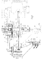
- Figure 1 shows a partially sectioned side view of a fluid mixing device, particularly for paint or industrial ink, in accordance with the teachings of the present invention;
- Figure 2 shows a section of a central portion of the Figure 1 device;
- Figure 3 shows a first detail of the Figure 1 device;
- Figure 4 shows a section of the first detail along line IV-IV in Figure 3;
- Figure 5 shows a section of the first detail along line V-V in Figure 3;
- Figure 6 shows a top plan view of a second detail of the Figure 1 device.
-
- Number 1 in Figure 1 indicates a fluid mixing device, particularly for paint or industrial ink. Mixing device 1 comprises a supporting structure 3 (shown partially) in turn comprising a
central structure 5, and a number of straight supporting andguide elements 7 equally spaced angularly and extending radially fromcentral structure 5. More specifically,central structure 5 comprises a cylindricaltubular body 10 coaxial with anaxis 11 and in turn comprising a first top end portion (not shown) fitted to a supporting frame (not shown), and a secondbottom end portion 10a fitted with anannular flange 12 extending outwards oftubular body 10. Each straight supportingelement 7 comprises astraight crosspiece 17 in turn comprising afirst end portion 17a fitted totubular body 10 and toflange 12 by a supportingelement 18, and asecond end portion 17b supporting aplate 20. Each straight supportingelement 7 also comprises a straight guide 22 (shown partially) fitted toplate 20 and extending parallel tocrosspiece 17 fromplate 20 totubular body 10; andstraight guides 22 are equally spaced angularly, and extend radially fromcentral structure 5. - A
slide 24 runs along eachguide 22, and comprises a substantiallyrectangular wall 25 from which extends integrally downwards atrapezoidal appendix 27 having anend portion 27a supporting a known three-way valve 29. -
Wall 25 is substantially coplanar with a plane throughaxis 11, and comprises atrapezoidal recess 25a facingcentral structure 5, and at the bottom of which is formed a substantially T-shaped seat 31. - Three-
way valve 29 comprises acylindrical casing 30, from the opposite ends of which there extend axially a downward-facingnozzle 34 and acontrol rod 35 facing supportingstructure 3. More specifically,control rod 35 comprises aknob 37 having a substantially T-shaped cross section, and the function of which is described later on. Valve 29 also comprises afluid inlet pipe 39 conveniently supplied with pressurized fluid, such as paint or industrial ink; and a recirculatingpipe 40 communicating with a fluid collecting tank (not shown). As described later on, eachslide 24 is movable between an idle position (shown by the continuous line in Figure 1) in whichslide 24 is located at a first end ofguide 22 close toplate 20, andvalve 29 is located a predetermined distance L fromaxis 11; and an operating position (shown by the dotted line in Figure 1) in whichslide 24 is located at a second end ofguide 22 close totubular body 10, andvalve 29 is coaxial withaxis 11. - Device 1 also comprises a
selecting device 42 extending axially fromtubular body 10 and movable angularly aboutaxis 11 as described later on. More specifically, tubular body 10 (Figure 2) houses acircular plate 46 perpendicular toaxis 11 and closingend portion 10a.Plate 46 is fitted stably totubular body 10 andannular flange 12 by means ofscrews 48, is connected byscrews 49 to a tubular sleeve 53 extending coaxially withaxis 11 and outwards oftubular body 10, and comprises a central through opening 55 coaxial withaxis 11 and communicating with the cylindrical inner cavity defined by tubular sleeve 53. Selectingdevice 42 comprises atubular element 57 coaxial withaxis 11 and defining a cylindricalinner cavity 57k housing sleeve 53. More specifically, sleeve 53 is connected totubular element 57 by twoball bearings cavity 57k and permittingtubular element 57 to rotate in axially-fixed manner about sleeve 53.Tubular element 57 comprises atop end portion 57a connected stably to aring gear 62 facingcircular plate 46 and substantially coplanar with the plane throughannular flange 12.Ring gear 62 meshes with apinion 64 fitted to theoutput shaft 66a of ahydraulic motor 66 in turn fitted tocircular plate 46 and housed insidetubular body 10. Ring gear 62 (Figure 6) comprises a first number of throughholes 69 equally spaced angularly about a first circumference C1, and a second number of throughholes 71 equally spaced angularly about a second circumference C2 inwards of first circumference C1; and eachhole 69 in the first number is separated by a constant angle α with respect to anadjacent hole 71 in the second number. Device 1 comprises anangular positioning device 73 for angularly positioning selectingdevice 42 aboutaxis 11, and which comprises a first and secondhydraulic actuator 76, 77 (both shown in Figure 6) fitted toplate 46, housed insidetubular body 10, and havingpins 79 movable axially to and fromring gear 62 through respective holes 81 (Figure 2) formed throughplate 46.Pin 79 of hydraulic actuator 76 (or 77) engages a respective hole 71 (or 69 in the case of actuator 77) to establish a predetermined stable angular position of ring gear 62 (and hencetubular element 57 integral with ring gear 62) aboutaxis 11 and with respect tocentral structure 5.Tubular element 57 houses arod 84 coaxial withaxis 11, extending through tubular sleeve 53 and opening 55, and comprising atop end portion 84a housed insidetubular body 10 and connected by ajoint 85 to theoutput member 87 of anactuator 88, e.g. a pneumatic cylinder (shown schematically in Figure 1), for movingrod 84 axially alongaxis 11. Joint 85 (known type) permitsrod 84 to rotate in relation tooutput member 87. -
Rod 84 comprises abottom end portion 84b projecting fromtubular element 57 and connected to anangular guide device 89, which comprises two flatrectangular walls 90 facing each other, connected stably to abottom end portion 57b oftubular element 57, and extending axially fromtubular element 57. Onewall 90 comprises a substantially rectangular slot 92 (Figures 1, 2, 3) extending parallel toaxis 11 and housing in rolling manner aroller 94 fitted in angularly free manner to a pin 95 extending radially fromrod 84. By virtue of the restraint defined byroller 94 and the walls ofslot 92,angular guide device 89 preventsrod 84 from rotating aboutaxis 11 in relation totubular body 57, but permits axial movement ofrod 84. At the free bottom end opposite the end secured totubular element 57,walls 90 are fitted with acircular plate 97 crosswise toaxis 11 and having a substantiallyrectangular slot 98 extending radially from the edge to the center of plate 97 (Figures 2 and 3). The end portion ofbottom end portion 84b ofrod 84 comprises aretaining seat 103 having a T-shaped cross section and extending radially inwards ofrod 84. - Selecting
device 42 also comprises apneumatic actuator 106 fitted totubular element 57, and which in turn comprises acylindrical body 107 projecting fromtubular element 57, and acontrol shaft 108 extending axially fromcylindrical body 107 and throughtubular element 57. More specifically,rod 84 comprises a diametrical, axially-elongated through opening 110 (Figure 4) through whichcontrol rod 108 extends and projects fromtubular element 57 through ahole 112.Control rod 108 comprises an end portion fitted with anengaging element 109 having a substantially T-shaped cross section and which engagesseat 31 inslide 24 as described later on. -
Pneumatic actuator 106 is connected to anaxial guide device 114 located on the opposite side oftubular element 57 tocylindrical body 107, and comprising a substantiallyrectangular flange 117 extending radially fromtubular element 57, and a pair ofidle rollers 119 fitted toflange 117 and located on either side ofcontrol shaft 108.Rollers 119 comprise annular V-shaped grooves (Figure 3) engaged by, and for axially guiding and preventing inflection of,control shaft 108, which is movable radially between a first extracted position in which engagingelement 109 is connectable toseat 31 of aslide 24 in the idle position, and a withdrawn position (Figure 2) in whichengaging element 109 is adjacent torollers 119 ofaxial guide device 114. - Device 1 also comprises an electronic control unit 130 (Figure 1) for controlling
motor 66,actuators pneumatic actuator 106, andactuator 88 activatingoutput member 87. - In actual use, at the start of the mixing cycle,
slides 24 of device 1 are all set to the idle position,valves 29 of device 1 are all located at distance L fromaxis 11, andcontrol shaft 108 is set to the extracted position. - To select a first valve,
electronic unit 130 activatesmotor 66 to rotate selectingdevice 42 aboutaxis 11, so thattubular body 57 rotates aboutaxis 11, andengaging element 109 ofcontrol shaft 108 travels along a path in the form of an arc of a circle extending successively through the T-shaped seats 31 ofadjacent slides 24 equally spaced angularly aboutaxis 11. Whenengaging element 109 is positioned at a predetermined T-shaped seat 31,unit 103stops motor 66, andactuator pin 79 insidehole ring gear 62 in relation to supportingstructure 3 and establish a predetermined stable angular position ofelement 109 in relation toslide 24. In which position (shown clearly in Figure 1),engaging element 109 is housed insideseat 31, and, by virtue of the T shape ofseat 31 andelement 109, axial displacement ofcontrol shaft 108moves slide 24 alongguide 22.Electronic unit 130 then operatespneumatic actuator 106 to movecontrol shaft 108 into the withdrawn position and so drawslide 24 towardscentral structure 5 andvalve 29 towardsaxis 11. -
Actuator 106 is arrested whenvalve 29 is coaxial with axis 11 (Figure 2), in which position,control rod 35 is housed insideslot 98, and the top portion ofknob 37 engages retainingseat 103. At this point,electronic unit 130 operatesactuator 88 to moveoutput member 87 axially away fromplate 46 and so moverod 84 axially upwards. Thebottom portion 84a ofrod 84 therefore moves away fromplate 97, taking with itknob 37, the T shape of which prevents it from withdrawing fromseat 103; and axial displacement ofrod 35 ofvalve 29 opens the valve (partially or fully) so that fluid flows fromnozzle 34 into a mixing vessel (Figure 1). Once a predetermined amount of fluid has been dispensed,electronic unit 130 again operatesactuator 88 to moveoutput member 87 axially towardsplate 46 andbottom portion 84a towardsplate 97 toclose valve 29. At which point,unit 130 operatesactuator 106 to pushslide 24 into the idle position, so thatrod 35 withdraws fromslot 98 andvalve 29 moves away fromaxis 11. Actuator 106 is arrested uponslide 24 reaching the idle position, at which point,actuator pin 79 fromhole ring gear 62 from supportingstructure 3. -
Electronic unit 103 then operatesmotor 66 to rotate selectingdevice 42 aboutaxis 11, connectengaging element 109 to afurther slide 24, and select afurther valve 29. The operations described above are then repeated for the further slide to successivelyposition valve 29 coaxial withaxis 11, open and close the valve, and resetslide 24 to the idle position. A number of different fluids may therefore be mixed in the mixing vessel by repeating the above selection and open/close operations for a number of valves. - The advantages of the present invention will be clear from the foregoing description. By employing a single actuating device (pneumatic actuator 106) for moving all of
slides 24, and hence all ofvalves 29, from the idle to the operating position, mixing device 1 comprises a limited number of component parts, and, being simpler in design, is cheaper and more reliable as compared with known devices.
Claims (13)
- A fluid mixing device, particularly for paint or industrial ink, comprising:a number of slides (24) supporting at least a respective normally-closed valve (29) comprising at least one fluid supply conduit (34), a fluid nozzle (34), and a control member (35) for at least partially opening the valve (29); characterised by,a supporting structure (3);each guide (22) supporting a respective slide (24) running along the guide (22);a number of guides (22) fitted to said supporting structure (3) and extending radially from a central portion (5) of the supporting structure (3);said selecting means (42) comprising an engaging device (106) fitted to said rotary portion (57) and having an engaging member (108, 109) movable radially between a first position and a second position;selecting means (42) fitted to said supporting structure (3); said selecting means (42) comprising at least a rotary portion (57) movable angularly about an axis of rotation (11) by drive means (66);
said rotary portion (57) being settable to a number of angular positions in which said engaging member (108, 109), set to said first position, engages a respective slide (24) set to an idle position; said engaging member (108, 109) being movable from said first position to said second position to move said slide (24) from said idle position to an operating position in which said valve (29) engages valve opening means (103) for at least partially opening the valve (29). - A device as claimed in Claim 1, characterized in that said valve opening means (84, 103) comprise engaging means (103) for engaging with said control member (35) of said valve (29); said engaging means being movable axially, along said axis of rotation (11) and by actuating means (88), between a valve closing position and a valve opening position.
- A device as claimed in Claim 2, characterized in that said valve opening means comprise a rod (84) fitted to said rotary portion (57) and slidable axially along said axis of rotation (11) by said actuating means (88); said rod (84) having an end portion (84b) on which is formed a retaining seat (103) for said control member (35) of said valve (29).
- A device as claimed in Claim 3, characterized in that said rotary portion comprises a tubular body (57) coaxial with said axis of rotation (11) and housing said rod (84) in axially-sliding manner.
- A device as claimed in Claim 3 or 4, characterized by comprising angular guide means (89) connected to said rod (84) and for preventing angular rotation of the rod (84) with respect to said rotary portion (57).
- A device as claimed in Claim 5, characterized in that said angular guide means (89) comprise at least a prismatic body (90) extending radially from said rod (84), and a straight guide (92) for said prismatic body (90); said guide (92) being integral with said rotary portion (57) and extending parallel to said axis of rotation (11).
- A device as claimed in any one of the foregoing Claims, characterized in that said engaging device comprises at least a linear actuator (106) fitted to said rotary portion (57) and having a control shaft (108) extending radially from said rotary portion (57) and movable axially between said first position and said second position; said control shaft (108) having, on a free end, an engaging element (109) for engaging a portion of said slide.
- A device as claimed in Claim 7, characterized in that said engaging element (109) comprises a body having a substantially T-shaped cross section;
each said slide having a substantially T-shaped seat (31) for housing said engaging element (109). - A device as claimed in Claim 7 or 8, characterized by comprising, for said control shaft (108), linear guide means comprising at least a pair of rollers (119) located on either side of the control shaft (108) and fitted to an appendix (117) extending from said rotary portion (57).
- A device as claimed in any one of the foregoing Claims, characterized by comprising angular positioning means (73) for establishing a number of stable angular positions of said rotary portion (57) with respect to said supporting structure (3).
- A device as claimed in Claim 10, characterized in that said angular positioning means (73) comprise a number of angularly spaced holes (69, 71) formed in a wall (62) integral with said rotary portion (57) and crosswise to said axis of rotation (11); and at least one actuator (76, 77) fitted to said supporting structure (3) and having an output member (79) movable axially to and from said wall (62) to individually engage said holes (69, 71).
- A device as claimed in Claim 10, characterized in that said angular positioning means (73) comprise:a first number of angularly spaced holes (69) located about a first circumference (C1) and formed in a wall (62) integral with said rotary portion (57) and crosswise to said axis of rotation (11);a first actuator (77) fitted to said supporting structure (3) and having an output member (79) movable axially to and from said wall (62) to individually engage said holes (69) in said first number;a second number of angularly spaced holes (71) located about a second circumference (C2) inwards of the first circumference (C1);a second actuator (76) fitted to said supporting structure (3) and having an output member (79) movable axially to and from said wall (62) to individually engage said holes (71) in said second number.
- A device as claimed in any one of the foregoing Claims, characterized by comprising angular motion transmission means interposed between said rotary portion (57) and said drive means (66); said transmission means comprising a ring gear (62) extending radially from said rotary portion (57), and a pinion (64) meshing with said ring gear (62) and moved angularly by said drive means.
Applications Claiming Priority (2)
| Application Number | Priority Date | Filing Date | Title |
|---|---|---|---|
| IT96TO000049A IT1284347B1 (en) | 1996-01-26 | 1996-01-26 | MIXING DEVICE FOR FLUIDS, IN PARTICULAR PAINTS OR INDUSTRIAL INKS |
| ITTO960049 | 1996-01-26 |
Publications (2)
| Publication Number | Publication Date |
|---|---|
| EP0786287A1 EP0786287A1 (en) | 1997-07-30 |
| EP0786287B1 true EP0786287B1 (en) | 2000-08-16 |
Family
ID=11414166
Family Applications (1)
| Application Number | Title | Priority Date | Filing Date |
|---|---|---|---|
| EP97101049A Expired - Lifetime EP0786287B1 (en) | 1996-01-26 | 1997-01-23 | Fluid mixing device, particularly for paint or industrial ink |
Country Status (4)
| Country | Link |
|---|---|
| EP (1) | EP0786287B1 (en) |
| DE (1) | DE69702778T2 (en) |
| ES (1) | ES2150709T3 (en) |
| IT (1) | IT1284347B1 (en) |
Families Citing this family (2)
| Publication number | Priority date | Publication date | Assignee | Title |
|---|---|---|---|---|
| IT1286835B1 (en) * | 1996-09-19 | 1998-07-17 | Giuseppe Guglielmetti | EQUIPMENT FOR DOSING AND DISTRIBUTION OF LIQUID AND SEMIQUID PRODUCTS |
| EP2365911B1 (en) | 2008-11-05 | 2015-01-07 | Füll Process S.A. | Colorant fluid dispensing device for dispensing multiple colorant fluids |
Family Cites Families (6)
| Publication number | Priority date | Publication date | Assignee | Title |
|---|---|---|---|---|
| US4046287A (en) * | 1976-05-10 | 1977-09-06 | Graco Inc. | Automatic metering and dispensing system |
| IT1165450B (en) * | 1979-09-28 | 1987-04-22 | Arrigoni Giordano | DISTRIBUTOR FOR STORAGE AND COLOR PREPARATION SYSTEMS |
| IT1161054B (en) * | 1983-02-08 | 1987-03-11 | Giordano Arrigoni | PERFECTING VARIABLE AND SELECTIVE FEEDING AND DOSAGE COMPLEXES (ASSEMBLIES) OF VARIOUSLY PIGMENTED AND / OR MIXED COLORS, FOR THE PREPARATION OF DYES IN GENERAL, AND RELATED PERFECTED FEEDING AND DOSAGE COMPLEXES |
| US4967938A (en) * | 1989-07-17 | 1990-11-06 | Fluid Management Limited Partnership | Paint dispensing apparatus |
| IT1261258B (en) * | 1993-09-13 | 1996-05-09 | Dromont Meccanica Srl | DOSING VALVE FOR AUTOMATIC DOSING DEVICE FOR FLUIDS, IN PARTICULAR INDUSTRIAL PAINTS |
| IT1267194B1 (en) * | 1994-12-07 | 1997-01-28 | Dromont S R L | MIXING DEVICE FOR FLUIDS, IN PARTICULAR PAINTS OR INDUSTRIAL INKS |
-
1996
- 1996-01-26 IT IT96TO000049A patent/IT1284347B1/en active IP Right Grant
-
1997
- 1997-01-23 ES ES97101049T patent/ES2150709T3/en not_active Expired - Lifetime
- 1997-01-23 DE DE69702778T patent/DE69702778T2/en not_active Expired - Lifetime
- 1997-01-23 EP EP97101049A patent/EP0786287B1/en not_active Expired - Lifetime
Also Published As
| Publication number | Publication date |
|---|---|
| ES2150709T3 (en) | 2000-12-01 |
| DE69702778T2 (en) | 2000-12-14 |
| ITTO960049A1 (en) | 1997-07-26 |
| EP0786287A1 (en) | 1997-07-30 |
| DE69702778D1 (en) | 2000-09-21 |
| ITTO960049A0 (en) | 1996-01-26 |
| IT1284347B1 (en) | 1998-05-18 |
Similar Documents
| Publication | Publication Date | Title |
|---|---|---|
| EP0715883B2 (en) | Fluid mixing device, particularly for industrial inks or paints | |
| US4436280A (en) | Valve actuator mechanism for lift-turn type valves | |
| EP1102670B1 (en) | Actuator for injection molding valve gate | |
| US5918816A (en) | Multifunction hand shower | |
| DE10230004B4 (en) | Flow rate control valve | |
| EP0786287B1 (en) | Fluid mixing device, particularly for paint or industrial ink | |
| US7007922B2 (en) | Rotating regulating device | |
| WO1994000310A1 (en) | Nozzle for ventilating or air conditioning installations, especially in motor vehicle interiors | |
| EP2171323A2 (en) | Operating mechanism and an assembly | |
| KR100563335B1 (en) | Device for operating a selector shaft, of a shift transmission | |
| US4595036A (en) | Rotary control valve having quick emergency exhausting means | |
| DE3209813C2 (en) | ||
| DE844873C (en) | Propeller with adjustable blade pitch and two rotating blades with pivot pins in one another | |
| WO1988001697A1 (en) | Hydraulic idling-regulating valve | |
| KR102239171B1 (en) | DC motor integrated type driver | |
| US20220324030A1 (en) | A docking arrangement for an additive manufacturing process | |
| US20160201824A1 (en) | Zero pocket valve | |
| KR102447921B1 (en) | A coupling device, a drive assembly for the coupling device, and a method of supplying a substrate | |
| US20220371279A1 (en) | A docking arrangement for an additive manufacturing process | |
| FI103831B (en) | Improved valve device | |
| KR920003581B1 (en) | Fluid opening and closing valve | |
| DE2730451C2 (en) | ||
| EP0466033A1 (en) | Window regulator, particularly for motor vehicles | |
| JPS6377641A (en) | Position indexing device | |
| JPH0618777U (en) | Valve actuator |
Legal Events
| Date | Code | Title | Description |
|---|---|---|---|
| PUAI | Public reference made under article 153(3) epc to a published international application that has entered the european phase |
Free format text: ORIGINAL CODE: 0009012 |
|
| AK | Designated contracting states |
Kind code of ref document: A1 Designated state(s): DE ES FR GB NL |
|
| 17P | Request for examination filed |
Effective date: 19980127 |
|
| GRAG | Despatch of communication of intention to grant |
Free format text: ORIGINAL CODE: EPIDOS AGRA |
|
| 17Q | First examination report despatched |
Effective date: 19991028 |
|
| GRAG | Despatch of communication of intention to grant |
Free format text: ORIGINAL CODE: EPIDOS AGRA |
|
| GRAH | Despatch of communication of intention to grant a patent |
Free format text: ORIGINAL CODE: EPIDOS IGRA |
|
| GRAH | Despatch of communication of intention to grant a patent |
Free format text: ORIGINAL CODE: EPIDOS IGRA |
|
| GRAA | (expected) grant |
Free format text: ORIGINAL CODE: 0009210 |
|
| AK | Designated contracting states |
Kind code of ref document: B1 Designated state(s): DE ES FR GB NL |
|
| REF | Corresponds to: |
Ref document number: 69702778 Country of ref document: DE Date of ref document: 20000921 |
|
| ET | Fr: translation filed | ||
| REG | Reference to a national code |
Ref country code: ES Ref legal event code: FG2A Ref document number: 2150709 Country of ref document: ES Kind code of ref document: T3 |
|
| PLBE | No opposition filed within time limit |
Free format text: ORIGINAL CODE: 0009261 |
|
| STAA | Information on the status of an ep patent application or granted ep patent |
Free format text: STATUS: NO OPPOSITION FILED WITHIN TIME LIMIT |
|
| 26N | No opposition filed | ||
| REG | Reference to a national code |
Ref country code: GB Ref legal event code: IF02 |
|
| REG | Reference to a national code |
Ref country code: FR Ref legal event code: PLFP Year of fee payment: 20 |
|
| PGFP | Annual fee paid to national office [announced via postgrant information from national office to epo] |
Ref country code: FR Payment date: 20151208 Year of fee payment: 20 Ref country code: ES Payment date: 20151214 Year of fee payment: 20 |
|
| PGFP | Annual fee paid to national office [announced via postgrant information from national office to epo] |
Ref country code: NL Payment date: 20160111 Year of fee payment: 20 |
|
| PGFP | Annual fee paid to national office [announced via postgrant information from national office to epo] |
Ref country code: DE Payment date: 20160119 Year of fee payment: 20 |
|
| PGFP | Annual fee paid to national office [announced via postgrant information from national office to epo] |
Ref country code: GB Payment date: 20160120 Year of fee payment: 20 |
|
| REG | Reference to a national code |
Ref country code: DE Ref legal event code: R071 Ref document number: 69702778 Country of ref document: DE |
|
| REG | Reference to a national code |
Ref country code: NL Ref legal event code: MK Effective date: 20170122 |
|
| REG | Reference to a national code |
Ref country code: GB Ref legal event code: PE20 Expiry date: 20170122 |
|
| REG | Reference to a national code |
Ref country code: ES Ref legal event code: FD2A Effective date: 20170428 |
|
| PG25 | Lapsed in a contracting state [announced via postgrant information from national office to epo] |
Ref country code: GB Free format text: LAPSE BECAUSE OF EXPIRATION OF PROTECTION Effective date: 20170122 |
|
| PG25 | Lapsed in a contracting state [announced via postgrant information from national office to epo] |
Ref country code: ES Free format text: LAPSE BECAUSE OF EXPIRATION OF PROTECTION Effective date: 20170124 |