EP0786207B1 - Entbeinungsmaschine mit geschlitzter Trennkammer - Google Patents
Entbeinungsmaschine mit geschlitzter Trennkammer Download PDFInfo
- Publication number
- EP0786207B1 EP0786207B1 EP97200182A EP97200182A EP0786207B1 EP 0786207 B1 EP0786207 B1 EP 0786207B1 EP 97200182 A EP97200182 A EP 97200182A EP 97200182 A EP97200182 A EP 97200182A EP 0786207 B1 EP0786207 B1 EP 0786207B1
- Authority
- EP
- European Patent Office
- Prior art keywords
- slots
- separation chamber
- chamber
- auger
- machine
- Prior art date
- Legal status (The legal status is an assumption and is not a legal conclusion. Google has not performed a legal analysis and makes no representation as to the accuracy of the status listed.)
- Expired - Lifetime
Links
- 238000000926 separation method Methods 0.000 title claims description 55
- 235000013372 meat Nutrition 0.000 claims description 37
- 210000000988 bone and bone Anatomy 0.000 claims description 29
- 230000006835 compression Effects 0.000 claims description 5
- 238000007906 compression Methods 0.000 claims description 5
- 238000011144 upstream manufacturing Methods 0.000 claims description 4
- 230000003247 decreasing effect Effects 0.000 claims description 2
- 235000013622 meat product Nutrition 0.000 description 4
- 239000000945 filler Substances 0.000 description 3
- 238000001125 extrusion Methods 0.000 description 2
- 238000010008 shearing Methods 0.000 description 2
- 241000251468 Actinopterygii Species 0.000 description 1
- VTYYLEPIZMXCLO-UHFFFAOYSA-L Calcium carbonate Chemical compound [Ca+2].[O-]C([O-])=O VTYYLEPIZMXCLO-UHFFFAOYSA-L 0.000 description 1
- 229910000831 Steel Inorganic materials 0.000 description 1
- 210000000845 cartilage Anatomy 0.000 description 1
- 235000019688 fish Nutrition 0.000 description 1
- 238000012986 modification Methods 0.000 description 1
- 230000004048 modification Effects 0.000 description 1
- 239000002245 particle Substances 0.000 description 1
- 235000015277 pork Nutrition 0.000 description 1
- 244000144977 poultry Species 0.000 description 1
- 235000013594 poultry meat Nutrition 0.000 description 1
- 235000020989 red meat Nutrition 0.000 description 1
- 235000013580 sausages Nutrition 0.000 description 1
- 239000010959 steel Substances 0.000 description 1
- 229940056345 tums Drugs 0.000 description 1
Images
Classifications
-
- A—HUMAN NECESSITIES
- A22—BUTCHERING; MEAT TREATMENT; PROCESSING POULTRY OR FISH
- A22C—PROCESSING MEAT, POULTRY, OR FISH
- A22C17/00—Other devices for processing meat or bones
- A22C17/04—Bone cleaning devices
Definitions
- This invention relates generally to a machine for deboning or separating meats, such as red meat, pork, poultry and fish from bone, cartilage or sinew. More particularly, the invention relates to such a machine having a perforated separation chamber with a plurality of elongated slots for improving the texture and quality of the recovered meats.
- the prior art deboning machine of the type to which the invention is directed includes a compression type conveyor screw or auger operating in a perforated conduit, otherwise referred to as a separation chamber, to convey bone connected meat from the feed end of the machine to the bone discharge end.
- a valve ring surrounds the downstream end of the auger in a manner creating a back pressure to provide a choke for controlling pressure within the separation chamber, thereby controlling extrusion through the perforations of the chamber of the separated meat.
- the separation chamber is typically of machined heavy duty steel for withstanding the high pressure during the deboning operation.
- the perforations extend between the inner and outer surfaces of the chamber wall, and present a plurality of sharp arcuate edges which, in cooperation with the fluted turns of the auger, function to strip the meat from its bone as the bone connected meat is moved progressively by the turns of the auger from the feed end to the bone discharge end.
- the separated meat in finely chopped or almost puree form, is channeled by the perforations into a separate meat collector for use as meat fillers and for the making of sausages, luncheon meats, meat patties, and the like.
- EP A 0132084 discloses a compression type deboning machine having an auger rotatable in one direction within a perforated separation chamber for separating meat from bone by the cooperation of sharp edges of the separation chamber and fluted turns of the auger upon conveyance of bone connected meat from a feed end of the machine in a downstream direction toward a discharge end, wherein perforations of separation chamber comprise a prurality of elongated slots, each formed of a pair spaced apart side walls presenting interior arcuate end edges, said slots being oriented such that said edges lie at an angle relative to the central axis of said separation chamber so as to be tilted in said one direction of auger rotation.
- the present invention provides a compression type deboning machine having an auger rotatable in one direction within a perforated separation chamber for separating meat from bone by the cooperation of the sharp edges of the separation chamber and fluted turns of the auger upon conveyance of bone connected meat from a feed end of the machine in a downstream direction toward a discharge end, wherein perforations of separation chamber comprise a plurality of elongated slots, each formed of a pair spaced apart side walls presenting interior side edges, and opposing arcuate end walls presenting interior arcuate and edges, said slots being oriented such that said edges lie at an angle relative to the central axis of said separation chamber so as to be tilted in said one direction of auger rotation, characterized in that said machine is provided with means for creating a back pressure to provide a choke controlling pressure within the separation chamber and in that said arcuate end walls of said slots lie at a predetermined reverse angle of the inner service of said chamber.
- the internal means for creating back pressure simplify the design of the machine; together with reverse angle of the slots a coarser texture of meat showing less abuse can be provided.
- the perforations of the separation chamber comprise a plurality of elongated slots presenting a plurality of sharp arcuate as well as straight edges to the advancing bone connected meat so as to be sheared or peeled away from the bone in cooperation with the rotating turns of the auger.
- the slots provided according to the invention may lie at an angle relative to the central axis of the separation chamber so as to be tilted in the direction of auger rotation.
- the slots may lie in rows forming annular zones in tandem, with the slot width in one or
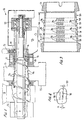
- the deboning machine generally designated 10 in the FIGS. 1 and 2
- the deboning machine has a compression type screw conveyor or auger 11 with a plurality of helical turns 12, the external dimension of which tapers conically from a large diameter to a smaller diameter in a forward direction (to the right in FIGS. 1 and 2).
- the auger operates in a separation chamber or perforated conduit 13 forming a truncated cone shaped to match the outer diameter of the auger turns.
- a product such as unboned meat, meat with attached sinew, or the like, is loaded into hopper 14 and is advanced from this feed end of the machine by the rotating auger to bone discharge end 15 of the machine.
- a ring valve 16 surrounds a forward extension 17 of the auger and is adjustable relative thereto for controlling the size of the annular discharge orifice located between the confronting surfaces of ring valve 16 and forward extension 17.
- the ring valve comprises an elongated sleeve threaded to a water-cooled valve housing 18 for adjustment along its central axis by the provision of a ratchet 19 having an operating handle 21. Movement of ring valve 16 along its axis adjusts the spacing between the confronting faces from an interface position constituting full choke to any desired size of annular discharge opening, as for the purpose and in the manner known in the art.
- the downstream end of the auger is supported in a bearing assembly 22, and between that assembly and the ring valve is a collection area 23 at which the comminuted bone after meat separation is discharged and collected.
- the auger is further supported in a bearing housing 24, and some type of receptacle 25 surrounds the separation chamber for collecting the separated meat product.
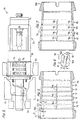
- FIG. 3 An illustrative example of a separation chamber 13 is more clearly shown in FIG. 3 as having a plurality of mutually spaced apart elongated openings 26 in the form of slots lying in adjacent annular rows each being spaced apart a predetermined distance 27 in the direction of the central axis of the chamber.
- the mutually spaced annular rows of slots form zones 28, 29, 31, 32, 33 and 34 in FIG. 3, there being a blank zone 35 adjacent zone 34 at the downstream end of the separation chamber.
- the slot width 37 can range from 0,05 to 0,25 CM (0.02 to 0.10 inches), and the slot length 38 can vary from 0,318 to 4,45 CM (0.125 to 1.75 inches)
- Each elongated slot comprises a pair of spaced apart side walls 46, and opposing arcuate end walls 47.
- the side walls and end walls respectively define inner elongated side edges 48 and arcuate end edges 49 presented to the turns of the auger.
- end walls 47 lie perpendicular to the inner surface of the separation chamber.
- the slot width in each of zones 28 and 29 was 0,13 CM (0.05 inches)
- the slot width 37 in each of zones 31 and 32 was 0.10 CM (0.04 inches)
- the slot width 37 in each of zones 33 and 34 was 0,08 CM (0.03 inches).
- each of the slots 26 in each of the zones is orientated to downwardly slope at an angle ⁇ (FIG. 4) relative to the central axis of the chamber in the direction of auger rotation shown by the curved arrow in FIG. 1.
- the downward slope of the slots in the direction of the bone discharge end 15 may be approximately 10°.
- the back pressure or choke provided by ring valve 16 controls the pressure within separation chamber 13 to thus control the extrusion or advance of the deboned meat through slots 26.
- Edges 48 and 49 of slots 26 are presented to turns 12 of the auger provide shearing edges which, together with the auger turns, facilitate a shearing of the meat from the bone through the slots, while the comminuted bone advances in a downstream direction toward the bone discharge end 15 and passes through the annular opening between the confronting conical surfaces of forward extension 17 and ring valve 16.
- Movement of the ring valve along its axis adjusts the spacing between such confronting surfaces from an interface position constituting full choke to any desired size of annular discharge opening, similarly as in the prior art.
- the recovered meat product is collected in receptacle 25, and the bone components are collected at area 23.
- the recovered meat product has been shown to exhibit less abuse compared to that obtained with prior art separators such that the recovered meat can be used as a primary meat source instead of as a filler.
- the orientation of slots 26 and the decreasing slot width from feed end to discharge end of the separation chamber, is selected according to the type of meat to be separated and the skeletal part to be processed.
- the separated meat obtained with the deboning machine according to the invention is coarser and has improved texture. Large particle separation of about one inch by about 0,15 CM (0.06 inch) by about 3,81 CM (1.5 inch)has been observed using the slotted separation chamber of the invention.
- the reduction in slot width in three stages from zone 28 to zone 34 function to increase the choke for increasing pressure within the separation chamber, and serve to increase the yield of the separated meat as the product advances from the feed end to the bone discharge end of the separation chamber.
- Slotted separation chamber 13A has slots 26A mutually spaced apart in annular spaced apart zones 28 to 34.
- the opposing arcuate end walls 51 of the slots are each formed as having a reverse angle X to the direction of advancement of the product through the separation chamber.
- Angle X may be about 60° relative to the central axis of the separation chamber.
- the slanted orientation of slots 26A such as at angle ⁇ which may be about 10°
- the length 38 of the slots, as shown in FIG. 6 are the same as that described with reference FIGS. 3 and 4.
- the width 37 of each of the slots 26A may vary between zones 28 and 34 similarly as described with reference to FIG. 3.
- the spacing 39 between the annular rows of slots 26A in the annular zones 28 to 34, measured at the inner wall surface of separation chamber 13A, is shorter compared to spacing 27 between the rows of slots in separation chamber 13.
- This shorter spacing 39 allows for the same number of six annular rows of slots as in separation chamber 13, and walls 51 present a series of sharp inner arcuate edges 41.
- These sharp edges present cutting edges to the turns of the auger when rotating about its axis in the direction of the curved arrow of FIG. 1, such that the meat is actually peeled away from its bone leaving coarser, highly textured and longer pieces of recovered meat from the bone compared to that obtained using prior art deboning machines.
- Separation chamber 13B of FIG. 7 is another illustration of a deboning chamber which is similar to that of separation chamber 13, except that the slot length is slightly longer compared to that of FIG. 3, and the slots lie in annular adjacent rows or zones 42, 43, 44 and 45 which zones are fewer in number compared to that of FIG. 3. Otherwise, the function and operation of the slotted separation chamber 13B is the same as that described with reference to FIG. 3. Separation chamber 13B is tailored to the type of product being deboned and the skeletal part being processed.
- the width of slots 26 in zones 42 and 43 may be about 0,15 CM (0.06 inches), and the width of the slots in zones 44 and 45 may be about 0,13 CM (0.05 inches).
- the slotted separation chamber according to the invention can be used with existing deboning machines or can be adapted to new design equipment.
- the slots can range from about 0,05 cm (0.02) inches to about 0,25 cm (0.10) inches in width and about 0,31 cm (0.125) inches to about 4,45 CM (1.75 inches) in length.
- edges 41 are presented to the tums of the auger which advance the product from the feed end to the bone discharge end of the separation chamber and serve to shear or peel away the recoverable meat from the bone and from the sinew to yield a coarser texture of meat showing less abuse and useable as a primary meat source, separate and distinct from the paste-like product typically resulting from mechanical deboning equipment.
Landscapes
- Life Sciences & Earth Sciences (AREA)
- Engineering & Computer Science (AREA)
- Wood Science & Technology (AREA)
- Zoology (AREA)
- Food Science & Technology (AREA)
- Meat, Egg Or Seafood Products (AREA)
- Processing Of Meat And Fish (AREA)
Claims (6)
- Entbeinungsmaschine (10) vom Kompressionstyp, mit einem Schneckenbohrer (11), der in einer Richtung innerhalb einer perforierten Trennkammer (13) drehbar ist, um Fleisch vom Knochen zu trennen durch das Zusammenwirken von scharfen Kanten der Trennkammer und eingekehlten Windungen (12) des Schneckenbohrers bei Förderung von mit Knochen verbundenem Fleisch von einem Zufuhrende der Maschine in Richtung stromabwärts zu einem Abgabeende, wobei Perforationen der Trennkammer mehrere längliche Schlitze (26, 26a) aufweisen, die jeweils ausgebildet sind aus einem Paar voneinander beabstandeter Seitenwände (46), die Innenseitenkanten präsentieren und gegenüberliegenden, gekrümmten Endwänden (47), die innere gekrümmte Endkanten präsentieren, wobei die Schlitze derart orientiert sind, daß die Kanten unter einem Winkel relativ zu der zentralen Achse der Trennkammer liegen, um in die eine Richtung der Drehung des Schnekkenbohrers geneigt zu sein, dadurch gekennzeichnet, daß die Maschine mit Einrichtungen versehen ist zur Erzeugung eines Rückdruckes, um einen Drosselsteuerdruck innerhalb der Trennkammer vorzusehen und daß die gekrümmten Endwände der Schlitze innerhalb eines vorbestimmten umgekehrten Winkels der Innenoberfläche der Kammer liegen.
- Maschine nach Anspruch 1, wobei die Schlitze (26, 26A) in mehreren ringförmigen Reihen liegen, die jeweils beabstandet sind um einen vorbestimmten Abstand entlang einer zentralen Achse des Schneckenbohrers.
- Maschine nach Anspruch 2, wobei die Schlitze in einer der Reihen bei einem stromaufwärts liegenden Ende der Kammer jeweils eine größere Breite haben als die Breite der Schlitze in einer der Reihen an einem stromabwärts liegenden Ende der Kammer, um dabei eine weitere Drosselung für den Steuerdruck innerhalb der Kammer vorzusehen.
- Maschine nach Anspruch 2 oder 3, wobei die Schlitzreihen jeweils eine Schlitzbreite haben, die sich größenmäßig von dem stromaufwärts liegenden zu dem stromabwärts liegenden Ende verringert, um dabei eine weitere Drosselung des Steuerdrucks innerhalb der Kammer vorzusehen.
- Maschine nach einem der Ansprüche 1 bis 4, wobei die gekrümmten Endwände der Schlitze senkrecht zu der Innenoberfläche der Kammer liegen.
- Maschine nach einem der Ansprüche 1 bis 5, wobei der Winkel etwa 30° ist.
Applications Claiming Priority (4)
| Application Number | Priority Date | Filing Date | Title |
|---|---|---|---|
| US1044496P | 1996-01-23 | 1996-01-23 | |
| US10444 | 1996-01-23 | ||
| US08/761,634 US5813909A (en) | 1996-01-23 | 1996-12-06 | Deboning machine with slotted separation chamber |
| US761634 | 1996-12-06 |
Publications (2)
| Publication Number | Publication Date |
|---|---|
| EP0786207A1 EP0786207A1 (de) | 1997-07-30 |
| EP0786207B1 true EP0786207B1 (de) | 2002-07-17 |
Family
ID=26681181
Family Applications (1)
| Application Number | Title | Priority Date | Filing Date |
|---|---|---|---|
| EP97200182A Expired - Lifetime EP0786207B1 (de) | 1996-01-23 | 1997-01-23 | Entbeinungsmaschine mit geschlitzter Trennkammer |
Country Status (5)
| Country | Link |
|---|---|
| US (1) | US5813909A (de) |
| EP (1) | EP0786207B1 (de) |
| CA (1) | CA2195506A1 (de) |
| DE (1) | DE69713920T2 (de) |
| DK (1) | DK0786207T3 (de) |
Families Citing this family (13)
| Publication number | Priority date | Publication date | Assignee | Title |
|---|---|---|---|---|
| DE19857138A1 (de) * | 1998-12-11 | 2000-07-20 | Nordischer Maschinenbau | Separiereinrichtung |
| US6622950B1 (en) | 2001-07-19 | 2003-09-23 | Weiler And Company, Inc. | Slot configuration for a separator with slotted walls |
| US7569245B2 (en) * | 2004-05-26 | 2009-08-04 | Kraft Foods Holdings, Inc. | Washed deboned meat having high protein recovery |
| US20050276451A1 (en) * | 2004-05-27 | 2005-12-15 | Hunking Maurice J | Method and apparatus for sorting |
| US8110234B2 (en) * | 2005-10-05 | 2012-02-07 | Chic Pic, Llc | Mechanical deboning of poultry |
| WO2007103799A2 (en) * | 2006-03-02 | 2007-09-13 | Weiler And Company, Inc. | Variable dimensioned separation chamber for food processor |
| AU2012362228B2 (en) * | 2011-12-29 | 2017-06-15 | Stryker Corporation | Bone cleaning assembly including cutter |
| US8951101B2 (en) * | 2012-02-13 | 2015-02-10 | Weiler And Company, Inc. | Deboning machine auger mount assembly |
| EP2830425A4 (de) * | 2012-03-26 | 2015-10-28 | Weiler & Co Inc | Trennkammern für entbeinungsmaschinen |
| EP3096624A4 (de) * | 2014-01-21 | 2017-03-22 | Weiler and Company, Inc. | Entbeinungsmaschine |
| PL3764801T3 (pl) * | 2018-03-16 | 2024-09-16 | Provisur Technologies, Inc. | Komora rowkowana do maszyny do rozdzielania produktów spożywczych |
| DE102019006557B3 (de) * | 2019-09-18 | 2020-08-27 | Packaging- & Cuttingsystems Von Der Weiden Gmbh | Zerkleinerungstrommel für eine Schneid- und Separiervorrichtung (Zuführkanal) |
| WO2024006784A1 (en) | 2022-06-30 | 2024-01-04 | Provisur Technologies, Inc | Powered separator gap control apparatus |
Family Cites Families (12)
| Publication number | Priority date | Publication date | Assignee | Title |
|---|---|---|---|---|
| CA1062539A (en) * | 1975-11-28 | 1979-09-18 | Chemetron Corporation | Process and apparatus for the mechanical separation of a combination of meats and bone |
| US4189104A (en) * | 1978-04-06 | 1980-02-19 | Beehive Machinery, Inc. | Deboning machine with bone expeller |
| FR2542575B1 (fr) * | 1983-03-17 | 1986-06-27 | Innovations Meca Alimentaires | Tete de separation mecanique de chair de son support, lequel est rejete sous forme de dechet |
| US4638954A (en) * | 1983-07-13 | 1987-01-27 | Poss Design Limited | Apparatus for the separation of mixtures of materials of different consistencies such as meat and bone |
| USRE33752E (en) * | 1983-07-13 | 1991-11-26 | Apparatus for the separation of mixtures of materials of different consistencies such as meat and bone | |
| CA1231581A (en) * | 1983-07-13 | 1988-01-19 | Poss Design Limited | Apparatus for the separation of mixtures of materials of different consistencies such as meat and bone |
| US4566640A (en) * | 1984-01-18 | 1986-01-28 | Beehive Machinery, Inc. | Separating machine having overlapping screw pump |
| FR2565851B1 (fr) * | 1984-06-14 | 1994-02-11 | Innovations Meca Alimentaires | Tete de separation mecanique destinee notamment au traitement des carcasses broyees et machine qui en est equipee |
| US4824027A (en) * | 1987-10-13 | 1989-04-25 | The Kartridg Pak Co. | Meat separating means and method |
| US5067926A (en) * | 1990-04-05 | 1991-11-26 | Richburg James B | Cylindrical sieve for meat deboning apparatus and method |
| US5306202A (en) * | 1992-08-09 | 1994-04-26 | The Kartridg Pak Co. | Deboning screen |
| US5580305A (en) * | 1995-06-02 | 1996-12-03 | Mcfarland; Archie R. | Method and machine for segregating meat from bone, heavy tissue, and skin |
-
1996
- 1996-12-06 US US08/761,634 patent/US5813909A/en not_active Expired - Lifetime
-
1997
- 1997-01-20 CA CA002195506A patent/CA2195506A1/en not_active Abandoned
- 1997-01-23 DE DE69713920T patent/DE69713920T2/de not_active Expired - Fee Related
- 1997-01-23 EP EP97200182A patent/EP0786207B1/de not_active Expired - Lifetime
- 1997-01-23 DK DK97200182T patent/DK0786207T3/da active
Also Published As
| Publication number | Publication date |
|---|---|
| CA2195506A1 (en) | 1997-07-24 |
| US5813909A (en) | 1998-09-29 |
| EP0786207A1 (de) | 1997-07-30 |
| DE69713920T2 (de) | 2003-02-20 |
| DE69713920D1 (de) | 2002-08-22 |
| DK0786207T3 (da) | 2002-11-04 |
Similar Documents
| Publication | Publication Date | Title |
|---|---|---|
| EP0786207B1 (de) | Entbeinungsmaschine mit geschlitzter Trennkammer | |
| CA1062539A (en) | Process and apparatus for the mechanical separation of a combination of meats and bone | |
| US3739994A (en) | Apparatus for producing de-boned meat products | |
| US4153208A (en) | Mincing machine for grinding up food | |
| USRE32060E (en) | Process for producing deboned meat products | |
| US3741772A (en) | Process for producing de-boned meat products | |
| US3906118A (en) | Process for de-boning meat or fish | |
| US20100200682A1 (en) | System, method and apparatus for processing bone product | |
| EP0753261B1 (de) | Vorrichtung zum Trennen eines aus Herz und Lungen bestehenden Guts | |
| US3266542A (en) | Machine for separating fragments of bone, gristle or sinew from comminuted meat | |
| EP2783572B1 (de) | Vorrichtung zum Trennen von Fleisch tierischer Herkunft von Knochen | |
| US3659638A (en) | Heavy duty machine for production of comminuted meat and other foods | |
| US4566640A (en) | Separating machine having overlapping screw pump | |
| EP1988782B1 (de) | Trennkammer mit variabler länge und variablem durchmesser für eine küchenmaschine mit einstellbaren schneidperforationen | |
| US4824027A (en) | Meat separating means and method | |
| EP0801902A1 (de) | Verfahren und Vorrichtung zum Trennen des Fleisches von Knochen | |
| US4953794A (en) | Single process desinewing and deboning machine and method | |
| US4077089A (en) | Process and apparatus for meat deboning | |
| US11570997B2 (en) | Conveying screw for a cutting and separating device | |
| EP4403035A1 (de) | Vorrichtung und verfahren zum trennen von fleisch von knochen | |
| CN114929394B (zh) | 用于切割和分离设备的切碎滚筒 | |
| USRE32050E (en) | Process for de-boning meat or fish | |
| CN86105295A (zh) | 米糠处理方法和设备 | |
| US4018389A (en) | High production mechanical separator machine | |
| RU2087196C1 (ru) | Способ тонкого измельчения мяса и устройство для его осуществления |
Legal Events
| Date | Code | Title | Description |
|---|---|---|---|
| PUAI | Public reference made under article 153(3) epc to a published international application that has entered the european phase |
Free format text: ORIGINAL CODE: 0009012 |
|
| AK | Designated contracting states |
Kind code of ref document: A1 Designated state(s): DE DK FR GB NL |
|
| 17P | Request for examination filed |
Effective date: 19980119 |
|
| RAP1 | Party data changed (applicant data changed or rights of an application transferred) |
Owner name: WEILER & COMPANY, INC. |
|
| 17Q | First examination report despatched |
Effective date: 20000113 |
|
| GRAG | Despatch of communication of intention to grant |
Free format text: ORIGINAL CODE: EPIDOS AGRA |
|
| GRAG | Despatch of communication of intention to grant |
Free format text: ORIGINAL CODE: EPIDOS AGRA |
|
| GRAH | Despatch of communication of intention to grant a patent |
Free format text: ORIGINAL CODE: EPIDOS IGRA |
|
| GRAH | Despatch of communication of intention to grant a patent |
Free format text: ORIGINAL CODE: EPIDOS IGRA |
|
| GRAA | (expected) grant |
Free format text: ORIGINAL CODE: 0009210 |
|
| AK | Designated contracting states |
Kind code of ref document: B1 Designated state(s): DE DK FR GB NL |
|
| REG | Reference to a national code |
Ref country code: GB Ref legal event code: FG4D |
|
| REF | Corresponds to: |
Ref document number: 69713920 Country of ref document: DE Date of ref document: 20020822 |
|
| ET | Fr: translation filed | ||
| PLBE | No opposition filed within time limit |
Free format text: ORIGINAL CODE: 0009261 |
|
| STAA | Information on the status of an ep patent application or granted ep patent |
Free format text: STATUS: NO OPPOSITION FILED WITHIN TIME LIMIT |
|
| 26N | No opposition filed |
Effective date: 20030422 |
|
| PGFP | Annual fee paid to national office [announced via postgrant information from national office to epo] |
Ref country code: GB Payment date: 20050111 Year of fee payment: 9 |
|
| PGFP | Annual fee paid to national office [announced via postgrant information from national office to epo] |
Ref country code: FR Payment date: 20050128 Year of fee payment: 9 Ref country code: DE Payment date: 20050128 Year of fee payment: 9 |
|
| PGFP | Annual fee paid to national office [announced via postgrant information from national office to epo] |
Ref country code: NL Payment date: 20050131 Year of fee payment: 9 Ref country code: DK Payment date: 20050131 Year of fee payment: 9 |
|
| PG25 | Lapsed in a contracting state [announced via postgrant information from national office to epo] |
Ref country code: GB Free format text: LAPSE BECAUSE OF NON-PAYMENT OF DUE FEES Effective date: 20060123 |
|
| PG25 | Lapsed in a contracting state [announced via postgrant information from national office to epo] |
Ref country code: FR Free format text: LAPSE BECAUSE OF NON-PAYMENT OF DUE FEES Effective date: 20060131 Ref country code: DK Free format text: LAPSE BECAUSE OF NON-PAYMENT OF DUE FEES Effective date: 20060131 |
|
| PG25 | Lapsed in a contracting state [announced via postgrant information from national office to epo] |
Ref country code: NL Free format text: LAPSE BECAUSE OF NON-PAYMENT OF DUE FEES Effective date: 20060801 Ref country code: DE Free format text: LAPSE BECAUSE OF NON-PAYMENT OF DUE FEES Effective date: 20060801 |
|
| REG | Reference to a national code |
Ref country code: DK Ref legal event code: EBP |
|
| GBPC | Gb: european patent ceased through non-payment of renewal fee |
Effective date: 20060123 |
|
| NLV4 | Nl: lapsed or anulled due to non-payment of the annual fee |
Effective date: 20060801 |
|
| REG | Reference to a national code |
Ref country code: FR Ref legal event code: ST Effective date: 20060929 |