BACKGROUND OF THE INVENTION
This invention relates to a wireless communication
apparatus and method that employ frequency hopping.
In a frequency hopping spread spectrum (FHSS) system,
usually a usable frequency band is divided into a plurality
of frequency bands (channels) having a fixed bandwidth and
the carrier wave of a signal is transmitted while shifting
from one channel to another. The particular channels to which
a shift is made are given by a hopping pattern (HP). In order
to perform communication using the FHSS system, it is
required that both the sending and receiving sides have the
same hopping pattern and that the system be operated in
synchronized fashion. More specifically, demodulation on
the receiving side must be performed while changing the
reception frequency on the receiving side to follow up the
hopping pattern on the sending side. That is, it is required
that one and the same hopping pattern be shared by the
wireless terminals on the sending and receiving sides in
order for communication between the two terminals to be
started.
In other words, a wireless terminal possesses only one
hopping pattern, which is set when communication starts, and
this wireless terminal is capable of communicating only with
a specific wireless terminal having the same hopping pattern.
Accordingly, in order for a plurality of wireless terminals
to communicate with one another simultaneously,
communication is carried out by applying time-division
multiplexing to communication time based upon the hopping
pattern used.
However, a problem arises with this method of
communicating. Specifically, when communication time is
time-division multiplexed by a single hopping pattern, in
the manner mentioned above, in a scenario in which a plurality
of wireless terminals communicate simultaneously, this
hopping pattern is shared in communication with the other
wireless terminals in time-division multiplexing. This
means that one wireless terminal cannot communicate
simultaneously with these wireless terminals and with
another new wireless terminal outside this group.
Further, methods of changing over frequency in
conventional wireless communication using frequency hopping
include a method of switching frequency every communication
frame in accordance with the hopping pattern and a method
of switching frequency during the course of a communication
frame.
When communication is performed, regardless of the
frequency switching method, a communication frame is
assembled by adding identification information such as the
system ID or individual ID onto the beginning of the
communication information and then transmitting the
assembled communication frame. The receiving side analyzes
the identification information of the received
communication frame and accepts the ensuing communication
information only if the identification information matches
that of the receiving apparatus.
Further, in voice communication, transmission of audio
information must be performed in continuous fashion owing
to the need for real-time communication. In data
communication, however, data cannot be transmitted
continuously. In other words, data are transmitted at such
time that the data are generated.
Accordingly, another system installed in the
neighborhood of one's own apparatus is capable of performing
data communication even it is communicating data with this
apparatus by using the same hopping pattern. However,
another wireless communication apparatus will not recognize
the fact that the neighborhood system is communicating using
the identical hopping pattern or a hopping pattern in which
frequencies are superposed.
Further, with the method of switching frequency in the
middle of a communication frame, identification information
cannot be added onto all frequencies to which a changeover
is made. This means that if an apparatus should happen to
receive data transmitted from a system installed in the
neighborhood, these data will be received accidentally as
data transmitted to that apparatus.
Document EP-A-0 650 304 describes a frequency hopping control
channel in a radio communication system. It discloses a technique for, when
changing frequency for using a hopping pattern, changing frequency for each
time slot and for performing communication by using different hopping patterns
between control frame and sound frame.
Document WO-A-95 06377 describes a method and apparatus for
operating with a hopping control channel in a communication system. It
discloses a technique for, when changing frequency for using a hopping pattern,
changing frequency for each data symbol or each frame.
Document US-A-5 381 443 describes a method and apparatus for
frequency hopping a signalling channel in a communication system. It discloses
a technique for, when changing frequency for using a hopping pattern, changing
frequency for each time slot.
SUMMARY OF THE INVENTION
Accordingly, an object of the present invention is to
provide a wireless communication apparatus and method in
which one wireless terminal is capable of communicating
simultaneously with a plurality of other wireless terminals
having a plurality of different hopping patterns.
According to the present invention, the foregoing
objects are attained by providing a wireless communication
apparatus according to claim 1.
According to the present invention, the foregoing
objects are attained by providing a wireless communication
method according to claim 8.
Additional features are recited in the subclaims.
Other features and advantages of the present
invention will be apparent from the following description
taken in conjunction with the accompanying drawings, in which
like reference characters designate the same or similar parts
throughout the figures thereof.
DESCRIPTION OF THE PREFERRED EMBODIMENTS
<First Embodiment>
(Description of elements)
Fig. 1 is a diagram illustrating the configuration of
a wireless communication system according to an embodiment
of the invention.
As shown in Fig. 1, the system is composed of wireless
terminals having a variety of functions. Shown in Fig. 1
are a public switched telephone network 101, a network
controller 102 having a public line interface, a
radiotelephone 103, a personal computer 104 to which a
wireless PC card (not shown) has been connected, a printer
105 having an internal wireless controller, a wireless LAN
adapter 106 having an Ethernet ®interface, and a LAN 107.
Any one of these terminals functions as a centralized
control station. The terminal serving as the centralized
control station generates the reference timing of
transmission frames and performs call control and
management/allocation of hopping patterns. The other
wireless terminals (terminal stations) operate based upon
the timing generated by the centralized control station and,
at the start of communication, send the centralized control
station a transmission request and a request for allocation
of a hopping pattern.
Fig. 2 illustrates the architecture of a wireless
control unit equipped with a wireless terminal.
As shown in Fig. 2, the unit includes a data input/output
interface such as a PCMCIA (personal computer memory card
international association) interface, a Centronics
interface or an Ethernet ® interface, a voice input/output
interface such as a handset interface of public switched
telephone network interface, an error correction processor
(ECC) 203, a CPU 204, a memory 205, a DMA controller 206,
an ADPCM codec 207, a channel codec (CHC) 208, a wireless
unit 209 and a data bus 210.
By changing the interfaces 201, 202, the wireless
control unit can be used as a variety of wireless terminals
without changing the construction of the unit.
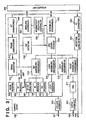
Fig. 3 is a diagram showing the internal construction
of the channel codec of Fig. 2. The channel codec 208 includes
a CPU data bus 301, a CPU bus interface 303, an ADPCM interface
304 for dealing with ADPCM-coded voice data 302, an ADPCM
interface 304, a mode register 305 for setting operating
data, a hopping-pattern register 306 capable of storing a
plurality of hopping patterns, a BF/NF register 307 for a
frame_number and/or next frequency number, a system ID
register 308, an intermittent start-up terminal address
register 309, an LCCH (logical control channel) register 310
for storing control data exchanged with a wireless terminal,
an FIFO buffer 311, a timing generator 312 for controlling
timing at which wireless link frames are sent and received,
a CNT channel assembler/disassembler 313 for performing an
exchange of system control data, an LCCH (logical control
channel) assembler/disassembler 314, a data
assembler/disassembler 315, a voice assembler/disassembler
316, a frame synchronizer 317, a unique-word detector 318,
a CRC coder/decoder 319, a bit synchronizer 320, a wireless
controller 321, an intermittent reception controller 322,
a scrambler/descrambler 323, an AD converter 324, and a
reception level detector 325 that outputs an interrupt signal
326. A wireless unit is indicated at 209.
Fig. 4 is a block diagram showing the architecture of
the wireless control section within the wireless control
unit. The wireless section includes transceiving antennae
401a, 401b, a switch 402 for changing over between the
antennae 401a, 401b, a bandpass filter (referred to as a
"BPF") 403 for removing signals in unnecessary bands, a
switch 404 for switching between transmission and reception,
an amplifier 405 for reception, an amplifier (with power
controller) 406 for transmission, a down-converter 407 for
a first IF (intermediate frequency), an up-converter 408,
a switch 409 for switching between transmission and
reception, a BPF 410 for eliminating signals in unnecessary
bands from the signal converted by the down-converter 407,
and a down-converter 411 for a second IF (intermediate
frequency). Double-conversion reception is implemented by
the down- converters 407 and 411.
The wireless unit further includes a second IF BPF 412,
a 90° phase shifter 413, a quadrature detector 414 for
detecting and demodulating a signal received by the BPF 412
and phase shifter 413, a comparator 415 for waveshaping, a
voltage-controlled oscillator (referred to as a "VCO" below)
416 for reception, a low-pass filter (referred to as an "LPF"
below) 417, and a phase-locked loop (referred to as a "PLL")
418 constituted by a programmable counter, prescaler and
phase comparator, etc. A frequency synthesizer in the
reception loop is constructed by the VCO 416, LPF 417 and
PLL 418.
The wireless section further includes a VCO 419 for
generating a carrier signal, an LPF 420 and a PLL 421
constituted by a programmable counter, prescaler and phase
comparator, etc., which are not shown. A frequency
synthesizer for hopping is constructed by the VCO 419, LPF
420 and PLL 421. Further provided are a VCO 422 located in
the transmission loop and having a modulating function, an
LPF 423, and a PLL 424 constituted by a programmable counter,
prescaler and phase comparator, etc., which are not shown.
A frequency synthesizer located in the transmission loop and
having a frequency modulating function is constructed by the
VCO 422, LPF 423 and PLL 424. An oscillator 425 generates
a reference clock for the PLLs 418, 421 and 424, and a filter
(baseband filter) 426 limits the band of transmission data
(the baseband signal).
Fig. 5 is a diagram showing the structure of a wireless
frame used in this wireless communication system.
As shown in Fig. 5, the frame includes a system control
channel (CNT) 501, a line control channel (LCCH) 502, a voice
channel 503 for performing voice communication, a data
channel 504 for performing data communication, and guard time
(a frequency changeover interval) CF 505 for the purpose of
changing frequency. Since the length of one frame is made
10 ms using this low-speed frequency hopping wireless unit
whose data transmission speed is 625 Kbps, 6250 bits of
information can be sent per frame.
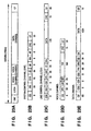
Figs. 6A ∼ D illustrate the details of each channel.
In each channel, CS, CS0, CS1 and CS2 represent carrier
sensing times, PR represents preamble time, SYN a frame
synchronizing signal, ID an identification code, BF a basic
frame number for communicating frame number information used
in hopping pattern control, WA a terminal identification
number which notifies of cancellation of a sleep mode (i.e.,
for starting up a terminal during intermittent reception),
NF a next hopping frequency (for updating the HP register),
Rev a reserve, CRC a redundant bit for error detection, GT
guard time, UW a unique word, and DA the terminal
identification number of the terminal that is the party to
communication. The numerical values below the channel
elements indicate the respective numbers of bits.
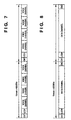
Figs. 7 and 8 illustrate other examples of frames. The
entirety of the frame in Fig. 7 is for voice channels
exclusively. The frame of Fig. 8 is for a data channel
exclusively, in which a maximum of 5588 bits of data can be
sent per frame. By suitably allocating the 6250 bits of one
frame according to each channel, frames in which the number
of voice channels and the amount of data communicated in data
channels are changed can be used in communication in addition
to the frames having the structure described above.
In this embodiment, the CNT channel and LCCH channel
use a first hopping pattern as a control channel, two voice
data channels use a second hopping pattern and a data channel
uses a third hopping pattern.
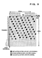
Fig. 9 is a conceptual view of frequency hopping used
in this system.
In the system according to this embodiment, use is made
of 26 frequency channels each having a width of 1 MHz,
utilizing a frequency band of 26 MHz. Taking into
consideration cases in which there are frequencies that
cannot be used because of interference noise, 20 frequency
channels are selected from the 26 channels and frequency
hopping is carried out over the selected frequency channels
in a predetermined order.
In this system, one frame has a length of 10 ms and a
different frequency channel is hopped every frame.
Consequently the length of the period of one hopping pattern
is 200 ms.
In Fig. 9, different hopping patterns are indicated by
different designs. Patterns in which the same frequencies
are not used at the same times are employed by each frame.
As a result, it is possible to prevent the occurrence of data
errors.
As shown in Fig. 10, in this system control is performed
in such a manner that a first hopping pattern (HP1) is used
in the CNT and LCCH channels, a second hopping pattern (HP2)
is used in the voice channel and a third hopping pattern (HP3)
is used in the data channel, as a result of which the channels
will not use the same frequency at the same time. This makes
it possible to send and receive data to and from a different
party per channel.
In order to reduce the number of hopping patterns
retained in the channel codec, the hopping patterns used by
the respective channels are generated by temporally shifting
patterns in which the frequencies are arranged in the same
order.
Fig. 11 illustrates the concept of four channels used
in this system and the frequency hopping corresponding to
each channel. Fig. 11 illustrates the manner in which the
control channels, voice channel and data channel undergo
hopping independently.
Basic control of the wireless control unit according
to this embodiment of the invention will now be described
in accordance with Figs. 2 through 11.
(Types of transmitted data)
The data transmitted in this system are broadly divided
into three types.
The first type of data is control data for performing
call control such as a transmission request. These data are
generated in accordance with a program that has been stored
in a ROM. The data are written to the LCCH register 310 in
the data codec 208 via the CPU data bus 210.
The second type of data is real-time data such as voice
data. These data are entered from the voice input/output
interface 202. An analog voice signal is converted to a
digital code by the ADPCM codec 207 and is acquired by the
channel codec 208 at a predetermined timing.
The third type of data is non-real-time data sent from
the memory of a personal computer or the like, by way of
example. These data are entered from the data input/output
interface 201 and are stored in the memory 205 by DMA transfer
under the control of the DMAC 206. When a prescribed amount
of these data are stored in the memory 205, coding is applied
by the error correction processor (ECC) 203, at which the
data are DMA-transferred to the channel codec 208.
It should be noted that when these data are received,
the data flow in a manner which is the exact opposite of that
described above.
(Operation of channel codec)
The channel codec 208 functions to assemble data in the
frame format shown in Fig. 5 and to send data, which have
been obtained by disassembling a frame, to the input/output
interface 201. The operation of the channel codec 208 will
now be described.
First, a reference for the operating timing of the
channel codec 208 is generated by the timing generator on
the side of the centralized control station described in
conjunction with the system of Fig. 1. The centralized
control station transmits a frame in accordance with this
timing, and a terminal that has received the frame maintains
frame synchronization in accordance with the frame
synchronizing word within the frame.
Data sent from the centralized control station by way
of the CNT channel are stored in a register within the channel
codec 208. The channel codec 208 has the HP (hopping-pattern)
register 306, the ID register 308 and the WA (start-up
terminal address) register 309. On the side of the
centralized control station, the internal CPU writes the
necessary values to these registers. The value within the
BF/NF register 307 for the frame number and/or next frequency
number is updated in sync with the operating timing. The
frequency number written to the NF register is the hopping
pattern (the first hopping pattern) of the CNT channel. The
channel codec 208 reads the data out of these registers at
the timing at which the data of the CNT channel are
transmitted, the data are assembled by the CNT assembler 31
and the assembled data are transmitted.
When the CNT channel is received at the terminal
station, the CNT assembler/disassembler 313 disassembles
the data of this channel and executes processing using the
value contained in each portion of the received channel.
More specifically, the terminal station determines whether
the received ID matches the value that has been written in
its own ID register 308, and control is performed in such
a manner that the ensuing data are received only if a match
is obtained. In a case where the received WA coincides with
the value in its own WA register 309 during intermittent
reception, the terminal station generates a start-up request
interrupt. Furthermore, the terminal station utilizes the
received BF, NF information and rewrites the content of the
data contained in the hopping-pattern register 306.
The frequency number that has been written in the NF
field of the CNT channel is that of the hopping pattern of
the CNT channel. Therefore, the hopping patterns used by
the voice channel and data channel are generated by
temporally shifting the hopping pattern created based upon
the frequency number that has been written in the NF field.
With regard to the LCCH channel, the CPU on the sending
side uses the LCCH assembler/disassembler 314 to assemble
the data that have been stored in the LCCH register 310 within
the channel codec 208. The assembled data are transmitted
at the predetermined timing. In order to prevent collision
with other terminals, the LCCH channel is provided with a
plurality of carrier sensing fields. Further, on the
receiving side, the received LCCH channel is disassembled
by the LCCH assembler/disassembler 314. Once the
disassembled data have been stored in the LCCH register 310,
an interrupt is generated and applied to the CPU. In response
to the interrupt, the CPU reads the data in the register.
With regard to the voice channel, the channel codec uses
the voice assembler/disassembler 316 to assemble data that
have entered via the ADPCM interface 304 and transmits the
assembled data at the predetermined timing. Conversely, on
the receiving side, the received voice channel is
disassembled by the voice assembler/disassembler 316 at the
predetermined timing and the results are outputted via the
ADPCM interface 304 at the timing at which processing is
performed in the ADPCM codec 207.
With regard to the data channel, the data are
transmitted only if the CPU has requested data transmission.
If data transmission has been requested, the CPU bus
interface 303 of the channel codec 208 outputs a DMA request
to the DMA controller (DMAC) 206 at the timing of every byte.
When the DMAC 206 responds to the DMA request and data is
written in, the data is converted to a serial one and
transmitted at the predetermined timing by the data
assembler/disassembler 315. Conversely, in a case where the
data channel is received, the data assembler/disassembler
315 converts the data to parallel data and outputs a DMA
request to the DMAC 206 byte by byte. The DMA controller
206 transfers the received data to the memory 205. When the
transmission of one frame of data ends, an interrupt is
generated and applied to the CPU. Upon receiving the
interrupt, the CPU executes processing such as processing
for acquiring memory for reception of the next frame.
When data are transmitted by all of the above-mentioned
channels, the CRC coder 319 generates a CRC code, stores the
code in the CRC field and then transmits the result. The
CRC is performed on the receiving side and the occurrence
of an error is detected. Further, all transmission data other
than the frame synchronizing word and unique word are
scrambled in the scrambler/descrambler 323. This is to
alleviate an imbalance in the transmitted data and to
facilitate the extraction of the synchronizing clock.
Conversely, when the frame synchronizing word or unique
word is detected at the time data reception, descrambling
is carried out in the scrambler/descrambler 323 at the timing
at which the word is received, a CRC check is carried out
and, at the same time, data are entered disassembled portion
of each field.
(Example of operation)
In this system as described above, control is such that
a frame composed of a plurality of channels for communication
between terminals is assembled and the frequency used is
changed over at regular time intervals.
The specific operation of this system will be described
for a case where a handset connected to a personal computer
is used to perform voice communication via the network
controller, a case where a personal computer performs a file
transfer with another personal computer, and a case where
the voice communication and data communication are carried
out simultaneously. In this embodiment, the description will
be rendered on the assumption that the network controller
connected to the public telephone line functions as a
centralized control station.
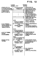
Fig. 12 is a sequence diagram showing a sequence of
operations performed by a control station and a terminal
station when power is introduced to the system, Fig. 13 is
a sequence diagram showing a call-control sequence up to the
start of data transmission or voice communication, Fig. 14
is a flowchart of a voice communication control operation
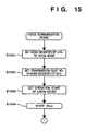
in a personal computer, Fig. 15 is a flowchart of operation
when voice communication starts, Fig. 16 is a flowchart of
a data communication control operation in a personal
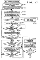
computer, Fig. 17 is a flowchart of a data communication
operation in a personal computer, Fig. 18 is a conceptual
view of time-divided channels and frequency hopping at the
time of voice communication, and Fig. 19 is a conceptual view
of time-divided channels and frequency hopping at the time
of data communication.
The invention will now be described in accordance with
these Figs. 12 through 19.
(Sequence of operations by control station
and terminal station at start-up)
When power is introduced and the terminal is
initialized at sequence S1201 in Fig. 12, the terminal
determines, based upon the set value in an external switch,
whether it is a control station or a terminal station. If
the terminal recognizes the fact that it is a control station,
then the station decides the first hopping pattern for the
control channel, assembles the synchronizing signal,
hopping pattern information and its own area number into a
frame and outputs the frame as the CNT frame at predetermined
timings.
Similarly, when the terminal recognizes, after
start-up, that it is a terminal station based upon the set
value in the external switch, then the station stores its
own address and the received area number of the control
station. When this processing ends, the terminal waits for
the CNT frame from the control station at any frequency. When
the CNT frame from the control station is received, the
hopping frequency is acquired in the next unit time based
upon NF in this frame. The terminal station changes the
reception frequency based upon this frequency and waits for
the next CNT frame. This processing is repeated at the
terminal station, the hopping pattern being used at the
control station is recognized and this hopping frequency is
stored in the HP register 306 in the channel codec 208.
When the storing of hopping patterns is finished at the
terminal station, the latter uses the LCCH frame at sequence
S1202 to notify the control station that it (the terminal
station) is being added on as a new terminal station. At
this time a global address which will be received by all
terminals is included in the DA of the LCCH frame, data
indicating that registration is performed anew are included
in the data portion of the LCCH frame and then the frame is
transmitted. The control station receives the LCCH frame
from the terminal station and, if a global address is present
in the DA of this frame, receives the data contained in the
data portion. If the data contains the address of the
terminal station and registration request data, then, on the
basis of this address and data, the control station stores
the address of the terminal station and registers the address
anew as the terminal station.
When registration is finished, the control station
notifies the newly registered terminal station of the address
of the control station using the LCCH frame at sequence S1203.
Upon receiving the address of the control station by way of
this LCCH frame, the terminal station stores the address of
the control station. When the above-mentioned processing
is finished, the terminal station uses the LCCH frame at
sequence S1204 to notify the control station of the fact that
start-up is completed. Upon receiving this notification of
completion of start-up from the terminal station, the control
station effects a transition to ordinary processing.
After outputting notification of end of start-up, the
terminal station is capable of making a transmission at
sequence S1205.
<Voice communication control>
When a transition is made to the transmission control
phase (step S1401 in Fig. 14) at the start of voice
communication, the terminal station determines whether
voice communication has been requested (S1402). If voice
communication has been requested ("YES" at step S1402), a
personal-computer voice communication application program
is started up (see Fig. 13). When this is done, a wireless
unit driver that has been installed in the personal computer
operates and sends the wireless control unit a voice
transmission request and a transmission destination number
(the extension number of the other party's terminal) via the
data input/output interface (S1403).
Next, the wireless control unit begins a call
origination procedure. Specifically, the wireless control
unit writes a call origination request command to the LCCH
register 310 in the channel codec 208 as LCCH data (S1404),
writes the address of the centralized control station to the
destination address register (S1405) and then sets the mode
register 305 of the channel codec 208 to the LCCH transmission
mode (S1406). At the time of LCCT transmission, carrier
detection is performed by the carrier sensing field in the
channel codec 208 (S1407). If a carrier is detected in this
period of time, it may be considered that another terminal
is using the LCCH channel. Accordingly, contention control,
which involves suspending data transmission until the next
frame, is carried out (S1408). If a carrier is not detected,
it may be considered that another terminal is not using the
LCCH channel. Accordingly, transmission of data to the
centralized control station is started (S1409). It should
be noted that the hopping pattern used in transmission of
the LCCH data is the first hopping pattern, which is the same
as that of the CNT channel.
Upon receiving the call origination request command,
the centralized control station executes call origination
processing, such as dialing a public telephone line. If an
answer is received from the called terminal via the public
telephone line, a termination notification command is sent,
by way of LCCH, to the personal computer that issued the
origination request. Furthermore, notification is given of
the hopping pattern (the second hopping pattern) which
prevails when the voice data are exchanged between the
personal computer and the centralized control station, and
notification is given of which of the two voice channels is
used on the sending side (S1410).
The personal computer, which has received notification
of call termination, the hopping pattern and allocation of
the channel used, sets the second hopping pattern used by
the call communication channel as well as the channel used
in the HP register 306 of the channel codec 208 and starts
the operation of the ADPCM codec (S1411). As a result, a
transition is made to the voice communication phase (S1413).
If reception of communication enable is not carried out at
S1410, then a busy indication is made at the terminal station
(S1412).
With regard to start of a call, the mode register 305
in the channel codec 208 is set to the voice mode (S1501 in
Fig. 15), the transmission slot number is set in the mode
register (S1502) and the start of operation of the ADPCM codec
is set (S1503).
The voice call starts (S1504) and it is determined at
S1601 in Fig. 16 whether there is a request for data
communication.
By virtue of this procedure, a link is established among
the personal computer, the network controller and the other
party's terminal and a call between the personal computer
and the other party's terminal begins.
During voice communication, the voice that has entered
from the handset provided on the personal computer is coded
by the ADPCM coder 207, the coded voice data enters the
channel codec 208, a preamble and a unique word are added
on every 160 bits, and the resulting data are scrambled and
then transmitted at the position of the predetermined voice
channel.
When bit synchronization is established in the preamble
section of the received voice data in the voice channel and
the unique word is detected at the time that audio is
received, descrambling is carried out. The descrambled data
are decoded by the ADPCM codec 207 and the decoded data are
outputted as a voice from the speaker of the handset.
At this time the frequency of the control channel is
changed over in the manner F1, F2, F3, F4, ··· in accordance
with the first hopping pattern, as shown in Fig. 10, and the
voice channel changes over the frequency in the manner F3,
F4, F5, F6, ···. Therefore, the changeover of frequency when
voice communication is being carried out is as shown in Fig.
18. That is, frequency changeover at the time of voice
communication is F1, F3, F2, F4, F3, F5, ···.
<Data communication control operation>
If voice communication is not requested at step S1402
in Fig. 14 and the terminal station issues a data
communication request at S1601 in Fig. 16 ("YES" at S1601),
a data communication application program in a personal
computer is started up and a wireless unit driver that has
been installed in the personal computer operates and sends
the wireless control unit a data transmission request and
a transmission destination number (the extension number of
the other party's terminal) via the data input/output
interface (S1602).
Next, a transition is made to a call origination
procedure similar to that executed in the case of voice
communication described above (S1603 ∼ S1608) and
transmission of the LCCH data to the centralized control
station begins.
Upon receiving the call origination request command,
the centralized control station notifies the other party's
terminal of call termination using the LCCH. If an answer
is sent back from the other party's terminal, the
establishment of the call is completed by sending two
terminals the hopping pattern (third hopping pattern) for
sending and receiving of data (S1608).
When the two terminals obtain the third hopping pattern
for sending/receiving data as the result of the foregoing
procedure (S1609), the third hopping pattern used is set in
the HP register of the channel codec 208 (S1611).
Sending/receiving of data is performed while the frequency
is changed over in accordance with the given hopping pattern
in the data channel (S1612). More specifically, the driver
of the wireless control unit transfers the data transmitted
from the memory 205 of the personal computer to the memory
205 of the wireless control unit (S1701), as shown in Fig.
17. If reception of communication enable is not carried out
at S1609 in data communication control as well, then a busy
indication is presented (S1610).
The wireless control unit subjects the data that has
been stored in the memory 205 to error correction coding and
stores the coded data in the memory 205 again (S1702). The
wireless control unit then sets an address for DMA transfer
from the memory 205 to the channel codec 208 in the DMA
controller 206 (S1703) and sets a transmission request in
the mode register 305 of the channel codec 208 (S1704). Upon
receiving the transmission request, the channel codec 208
performs carrier detection (S1705). If a carrier is
detected, the channel codec 208 stands by for one frame
(S1706). If a carrier is not detected, then the channel codec
208 generates a DMA request in one byte units in conformity
with the timing of the data channel. Upon receiving the DMA
request, the DMA controller transfers the data in the memory
205 to the channel codec 208 (S1707). The channel codec 208
adds on the preamble and the unique word, scrambles the data
and then transmits the scrambled data (S1708).
When transmission of one packet is finished ("YES" at
step S1708), an interrupt is generated in the CPU (S1709).
If there are data still to be transmitted, then the program
returns to step S1703 and transmission processing is executed
(S1710).
In a case where there are no data to be transmitted,
it is determined whether there is a request for voice
communication (S1711). If voice communication has already
been carried out, a request for voice communication is not
issued anew. However, if only data communication has been
carried out and voice communication is requested anew, then
the program proceeds to S1402 of Fig. 14.
If voice communication is not requested at S1711, then
the mode register 305 in the channel codec 208 is set to the
reception mode and reception is awaited (S1712).
In the wireless control unit on the receiving side, the
DMA controller is set beforehand to a mode for transfer from
the channel codec 208 to the memory 205. When data are
received ("YES" at S1713), bit synchronization is
established in the preamble section of the received data in
the channel codec 208. When a unique word is detected,
descrambling is performed. In addition, a DMA request is
generated in units of one byte in the data section. Upon
receiving the DMA request, the DMA controller transfers data
from the channel codec 208 to the memory 205 (S1714). When
transfer of one packet of data is finished, a reception-completion
interrupt is generated by the channel codec 208
and the CPU applies error correction demodulating processing
to the data stored in the memory 205. As a result, the final
reception data are obtained and the data are transferred to
the personal computer (S1715).
Transmission of data can be carried out through the
procedure described above. In a case where there are data
still to be transmitted, the same procedure is repeated by
reason of the fact that execution of the application is
unfinished ("NO" at S1716). This makes it possible to
transmit an unlimited amount of data.
As shown in Fig. 10, the changeover of frequency of the
control channel when data communication is being carried out
in the manner described above is F1, F2, F3, F4, ···, and
the changeover of frequency of the data channel is F5, F6,
F7, F8, ···.
In other words, the changeover of frequency for data
communication only (voice communication is not performed)
is F1, F5, F2, F6, F3, F7, ···, as shown in Fig. 19.
<Other forms of communication>
Described next will be a case where a request for data
communication shown in Figs. 16 and 17 is issued while voice
communication illustrated in Figs. 14 and 15 is in progress,
i.e., a case where a file transfer is performed between a
first personal computer and a second personal computer while
voice communication is being carried out via a network
controller using a handset connected to the first personal
computer.
The hopping patterns used in simultaneous voice
communication and data communication are decided
individually just as at the time of voice communication and
at the time of data communication. That is, both forms of
communication are carried out using entirely different
hopping patterns. The personal computer that performs voice
communication and data communication simultaneously stores
the first hopping pattern for the control channel, the second
hopping pattern for the voice channel and the third hopping
pattern for the data channel in the HP register 306 of the
channel codec 208.
The wireless unit 209 performs communication by
changing over frequency in accordance with the three hopping
patterns that have been stored in the HP register 306 of the
channel codec 208.
More specifically, as shown in Fig. 10, the wireless
unit abides by the hopping pattern (F1, F2, F3, F4, ···) of
the control channel, the hopping pattern (F3, F4, F5, F6,
...) of the voice channel and the hopping pattern (F5, F6,
F7, F8, ···) of the data channel, and frequency is changed
over in the manner F1, F3, F5, F2, F4, F6, F3, F5, F7, ···,
as depicted in Fig. 11.
<Call termination control>
A case where an incoming call is terminated at a wireless
terminal will now be described.
Fig. 20 is a flowchart of the operation performed by
the control station in a case where an incoming call from
the public switched telephone network is terminated at the
network control station, and Fig. 21 is a flowchart of
operation performed by the wireless terminal in a case where
an incoming call from the public switched telephone network
is terminated at the network control station.
When an incoming call from the public switched
telephone network is terminated at the network control
station (at step S2001 in Fig. 20), the control station writes
a call termination command to the LCCH register 310 of the
channel codec 208, writes the address of the terminating
wireless terminal to the destination address register 328,
then sets the mode register 305 of the channel codec 208 to
the LCCH transmission mode and notifies the terminating
wireless terminal of the fact that there is an incoming call
(S2002). The hopping pattern used in transmission of the
LCCH data is the first hopping pattern, which is the same
as that of the CNT channel.
The wireless terminal (a personal computer in this
embodiment) that has received the termination command ("YES"
at S2101) executes termination processing, such as issuance
of an incoming call tone, to notify the user of the incoming
call (S2102). When an answer corresponding to the incoming
call is made by the user (S2103), the wireless terminal writes
a termination answer command to the LCCH register 310 in the
channel codec 208 in order to notify the control station of
the fact that the incoming call has been answered, writes
the address of the centralized control station to the
destination address register, then sets the mode register
305 of the channel codec 208 to the LCCH transmission mode
and notifies the centralized control station of the fact that
the incoming call has been answered (S2104).
Upon receiving the termination answer command (S2003),
the centralized control station notifies the answering
personal computer of the hopping pattern used when data
transmitted to the public telephone line or received from
the public telephone line are exchanged between the personal
computer and the centralized control station (S2004).
Here, with regard to the incoming call from the public
telephone line, all data will be regarded as voice data and
it will be assumed that the hopping pattern of which the
personal computer is notified also is the second hopping
pattern for the voice channel. The reason for this is that
since all of the data sent from the public telephone line
arrive upon being modulated as voice data, the data can be
treated as voice data even if they are facsimile data or data
from personal computer.
When notification of the hopping pattern used ends, the
centralized control station makes a transition to the voice
communication phase just as at the time of origination of
the outgoing call (S2005).
If the termination answer command from the personal
computer is not received at S2003, the control station judges
that the personal computer is incapable of communicating and
notifies the public telephone line of the fact that the
personal computer is busy (S2006).
If the personal computer that has notified the
centralized control station at S2104 that it has answered
the incoming call has its hopping pattern allocated by the
centralized control station ("YES" at S2105), the personal
computer sets the hopping pattern number used by the voice
communication channel and the channel used in the HP register
306 of the channel codec 208 and starts the operation of the
ADPCM codec (S2106). The personal computer then undergoes
a transition to the voice communication phase similar to that
which prevailed when the outgoing call was originated.
If it is found at step S2105 that allocation of the
hopping pattern has not been performed, then the personal
computer transmits the termination answer command to the
centralized control station again.
If the personal computer issues an origination request
for data communication while it is performing communication
in response to an incoming call from the public telephone
line, the above-described origination control phase for data
communication is carried out. Even if the personal computer
is already performing data communication, it is capable of
carrying out the above-described termination control phase
if there is an incoming call.
Thus, as described above, communication using the
control channel, the voice channel and the data channel is
performed in accordance with hopping patterns that differ
from one another. As a result, one wireless terminal can
communicate simultaneously with a plurality of other
wireless terminals having different hopping patterns.
<Second Embodiment>
A second embodiment of the present invention will now
be described. The wireless communication system and wireless
control unit of this embodiment have architectures identical
with those of the wireless communication system and wireless
control unit according to the first embodiment.
Fig. 22 is a block diagram showing the architecture of
a channel codec in a system according to the second embodiment
of the invention. The codec includes an address register
328 for storing the address which is the destination of
communication. The other components of this codec are the
same as those in the channel codec of the first embodiment
illustrated in Fig. 3.
Figs. 23A ∼ 23E are diagrams showing the structures of
wireless frames used in the system according to the second
embodiment. The basic components are the same as those of
the wireless frames used in the system according to the first
embodiment. The difference between the first and second
embodiments in terms of the wireless frame elements is that
each channel of the wireless frames according to the second
embodiment has a system ID (ID) for receiving only data from
the centralized control station that belongs to the same
system. By thus providing an ID portion for each channel,
it is possible to prevent the system from accidentally
receiving data transmitted by another system.
The concept of frequency hopping used in the system
according to this embodiment and the hopping patterns are
the same as those used in the system according to the first
embodiment.
The basic operation of the wireless control unit
according to this embodiment will be described.
Since each channel of the wireless frames in this
embodiment is provided with the ID portion, as mentioned
above, the wireless control unit performs the operation,
described below, using this ID.
In the LCCH channel shown in Fig. 23C, the CPU on the
sending side uses the LCCH assembler/disassembler 314 to
assemble the data that have been stored in the LCCH register
310 and the data in the ID register 308 within the channel
codec 208. The assembled data are transmitted at the
predetermined timing. On the receiving side, the received
LCCH channel is disassembled by the LCCH
assembler/disassembler 314. If and only if the received
system ID matches the value that has been written in its own
ID register 308, the receiving side stores the disassembled
data in the LCCH register 310. Once this has been done, an
interrupt is generated and applied to the CPU. In response
to the interrupt, the CPU reads the data in the register.
With regard to the voice channel, the channel codec uses
the voice assembler/disassembler 316 to assemble data that
have entered via the ADPCM interface 304 and data in the ID
register 308 and transmits the assembled data at the
predetermined timing. Conversely, on the receiving side,
the received voice channel is disassembled by the voice
assembler/disassembler 316 at the predetermined timing and
the results are outputted via the ADPCM interface 304, at
the timing at which processing is performed in the ADPCM codec
207, only if the received system ID matches the value that
has been stored in the receiving side's own ID register 308.
With regard to the data channel, the data are
transmitted only if the CPU has requested data transmission.
If data transmission has been requested, the CPU bus
interface 303 of the channel codec 208 outputs a DMA request
to the DMA controller (DMAC) 206 at the timing of every byte.
When the DMAC 206 responds to the DMA request and data is
written, the data is converted to a serial one by the data
assembler/disassembler 315, the data is assembled together
with the data in the ID register 308 and the resulting data
are transmitted at the predetermined timing. Conversely,
in a case where the data channel is received, the data
assembler/disassembler 315 disassembles the data and, if the
received system ID matches the value that has been written
in the receiving side's own ID register 308, converts the
data to parallel data. Operation from this point onward is
the same as that of the first embodiment.
The operation of the system according to this
embodiment will now be described. Here also it will be
assumed that the network controller connected to the public
telephone line functions as a centralized control station.
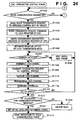
<Voice communication control operation>
Fig. 24 is a flowchart showing a voice communication
control operation according to this embodiment. Processing
steps identical with those of the voice communication control
operation according to the first embodiment shown in Fig.
14 are designated by like step numbers and need not be
described again. Further, processing following transition
to the voice communication phase is the same as illustrated
in Fig. 15.
In a case where a carrier is not detected at step S1407
in Fig. 24, it may be considered that another terminal is
not using the LCCH channel. Accordingly, in this embodiment,
the data in the LCCH register 310, the address register 328
and the ID register 308 are read out, the frame of the logical
control channel is assembled (S1108) and transmission of data
to the centralized control station is started (S1409).
When the LCCH channel is received on the side of the
personal computer by way of the first hopping pattern
(S1110), the LCCH assembler/disassembler 314 in the channel
codec 208 disassembles the received LCCH frame (S1111). The
system ID sent in the system ID portion and the system ID
in the ID register of the channel codec are compared and it
is determined whether the address sent in the
transmission-destination address portion matches the
address on the side of the personal computer (S1112). If
the result is that the system IDs match and the address is
that of the terminal on the receiving side ("YES" at S1113),
then the ensuing data are received. In other words, the
notification of call termination, the hopping pattern and
allocation of the channel used are received (S1410).
When bit synchronization is established in the preamble
section of the received voice data in the voice channel, the
unique word is detected and the system ID matches the system
ID in the ID address register 308 at the time that audio is
received, descrambling is carried out. The descrambled data
are decoded by the ADPCM codec 207 and the decoded data are
outputted as a voice from the speaker of the handset.
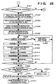
<Data communication control operation>
Figs. 25 and 26 are flowcharts showing a data
communication control operation according to the second
embodiment. Processing steps identical with those of the
data communication control operation according to the first
embodiment shown in Figs. 16 and 17 are designated by like
step numbers and need not be described again.
In a case where a carrier is not detected at step S1606
in Fig. 25, it may be considered that another terminal is
not using the LCCH channel. Accordingly, the data in the
LCCH register 310, the address register 328 and the ID
register 308 are read out, the frame of the LCCH channel is
assembled (S1308) and transmission of data to the centralized
control station is started (S1608).
When the LCCH channel is received on the side of the
personal computer by way of the first hopping pattern
(S1310), the LCCH assembler/disassembler 314 in the channel
codec 208 disassembles the received LCCH frame (S1311).
The system ID sent in the system ID portion and the
system ID in the ID register of the channel codec are compared
and it is determined whether the address sent in the
transmission-destination address portion matches the
address on the side of the personal computer (S1312). If
the result is that the system IDs match and the address is
that of the terminal on the receiving side ("YES" at S1313),
then the ensuing data are received. In other words, the
notification of call termination, the hopping pattern and
allocation of the channel used are received (S1609).
When a transition is made to the data communication
phase and a carrier is not detected at step S1705 in Fig.
26, then a DMA request is generated in one byte units in
conformity with the timing of the data channel. Upon
receiving the DMA request, the DMA controller transfers the
data to the memory 205 of the channel codec 208 (S1707). The
channel codec 208 adds the preamble, the unique word and the
system ID in the ID register 308 onto the data, assembles
the LCCH channel (S1408) and then scrambles the data and
transmits the scrambled data (S1708).
If data are received ("YES" at S1713) after the mode
register of the channel codec is set to the reception mode
(S1712), the data assembler/disassembler disassembles the
LCCH channel in the channel codec 208 (S1415). Bit
synchronization is established in the preamble section, the
unique word is detected and the system ID in the system ID
portion is compared with the system ID in the ID register
308 (S1416). If the two system IDs match ("YES" at S1417),
descrambling is carried out.
Operation in a case where data communication is
requested during the time that voice communication is in
progress is the same as that described in the first
embodiment. However, when communication is carried out while
changing over frequency in accordance with the three
above-mentioned hopping patterns that have been stored in
the HP register in the system according to this embodiment,
the system ID in the ID register 308 is added on for every
channel transmitted at the frequency to which the changeover
has been made. Data are received on the receiving side only
if the received system ID matches the system ID in the ID
register.
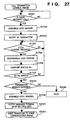
<Termination control operation>
Call terminal control in the system according to this
embodiment will now be described.
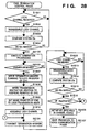
Fig. 27 is a flowchart illustrating the control
procedure performed by the control station when an incoming
call is terminated, and Fig. 28 is a flowchart illustrating
the control procedure performed by the wireless terminal when
an incoming call is terminated. Processing steps in Figs.
27 and 28 identical with those of the control procedure shown
in Figs. 20 and 21 are designated by like step numbers and
need not be described again.
When an incoming call from the public telephone line
is terminated at the network control station (S2001) in Fig.
27, the control station writes a call termination command
to the LCCH register 310 of the channel codec 208, writes
the address of the terminating wireless terminal to the
destination address register 328, then sets the mode register
305 of the channel codec 208 to the LCCH transmission mode.
The control station reads the call termination command out
of the LCCH register 310, reads the address of the terminating
wireless terminal out of the address register 328, reads the
system ID out of the ID register 308 and assembles the LCCH
channel (S1702). The control station gives notification of
the incoming call by transmitting the LCCH channel to the
terminating wireless terminal (S2002).
The wireless terminal (a personal computer in this
embodiment) that has received the above-mentioned LCCH
channel (S1801 in Fig. 28) disassembles the LCCH channel by
the LCCH assembler/disassembler 314 in the channel codec 208
(S1802) and compares the system ID in the system ID portion
and the system ID in the ID register 308 (S1803). If the
two system IDs match ("YES" at S1804), then the ensuing data
are received and the personal computer executes termination
processing, such as issuance of an incoming call tone, to
notify the user of the incoming call (S2102). When an answer
corresponding to the incoming call is made by the user ("Yes"
at S2103), the personal computer writes a termination answer
command to the LCCH register 310 in the channel codec 208
in order to notify the control station of the fact that the
incoming call has been answered (S1807), writes the address
of the centralized control station to the destination address
register (S1808), then sets the mode register 305 of the
channel codec 208 to the LCCH transmission mode (S1809). The
personal computer reads the termination answer command out
of the LCCH register 310, reads the address out of the address
register 328, reads the system ID out of the ID register 308
and assembles the LCCH channel (S1810). By transmitting this
channel, the personal computer notifies the centralized
control station of the fact that the incoming call has been
answered (S2104).
Upon receiving the LCCH channel ("YES" at S1704), the
centralized control station disassembles the LCCH channel
by the LCCH assembler/disassembler 314 in the channel codec
208 (S1705) and compares the system ID in the system ID
portion and the system ID in the ID register 308 (S1706).
If the two system IDs are found to match ("YES" at S1707),
then the ensuing data are received, whereby the termination
answer command is received ("YES" at S1708). In order to
notify the answering personal computer of the hopping pattern
used when data transmitted to the public telephone line or
received from the public telephone line are exchanged between
the personal computer and the centralized control station,
the LCCH channel to which the system ID, etc. have been added
on is assembled again (S1709) and this is transmitted to the
personal computer (S2004).
When notification of the hopping pattern used ends, the
centralized control station makes a transition to the voice
communication phase just as at the time of origination of
the outgoing call (S2005).
If the personal computer that has notified the
centralized control station that it has answered the incoming
call subsequently receives the LCCH channel ("YES" at step
S1812 in Fig. 28), the LCCH channel is disassembled by the
LCCH assembler/disassembler 314 in the channel codec 208
(S1813). The system ID in the system ID portion is then
compared with the system ID in the ID register 308 (S1814).
If these system IDs match ("YES" at step S1815), then the
ensuing data are received.
When the hopping pattern used is allocated by the
centralized control station in accordance with the data
received ("YES" at S1816), the second hopping pattern used
in the voice communication channel and the channel used are
set in the HP register 306 of the channel codec 208 and
operation of the ADPCM codec is started (S2106). The personal
computer then undergoes a transition to the voice
communication phase similar to that which prevailed when the
outgoing call was originated (S2107).
If it is found at step S1816 that allocation of the
hopping pattern has not been performed, then the program
returns to step S2104 and the personal computer transmits
the termination answer command to the centralized control
station again.
Thus, as described above, the system ID is added onto
the control channel, voice channel and data channel in which
communication is performed at frequencies that differ from
one another. Therefore, even if another system is performing
communication at the same frequency, data will no longer be
received accidentally.
Thus, it is possible to prevent the accidental
reception of data from another system even in a
frequency-hopping communication apparatus in which
frequency is changed over in the middle of a communication
frame.