EP0785367B1 - Palier - Google Patents
Palier Download PDFInfo
- Publication number
- EP0785367B1 EP0785367B1 EP96100619A EP96100619A EP0785367B1 EP 0785367 B1 EP0785367 B1 EP 0785367B1 EP 96100619 A EP96100619 A EP 96100619A EP 96100619 A EP96100619 A EP 96100619A EP 0785367 B1 EP0785367 B1 EP 0785367B1
- Authority
- EP
- European Patent Office
- Prior art keywords
- sleeve
- cage
- ball cage
- bearing
- flanged
- Prior art date
- Legal status (The legal status is an assumption and is not a legal conclusion. Google has not performed a legal analysis and makes no representation as to the accuracy of the status listed.)
- Expired - Lifetime
Links
- 229920003023 plastic Polymers 0.000 claims abstract description 4
- 239000004033 plastic Substances 0.000 claims abstract description 4
- 229910000760 Hardened steel Inorganic materials 0.000 claims description 3
- 239000000463 material Substances 0.000 claims description 3
- 238000005096 rolling process Methods 0.000 claims description 3
- 230000002093 peripheral effect Effects 0.000 claims description 2
- 238000003780 insertion Methods 0.000 abstract description 4
- 230000037431 insertion Effects 0.000 abstract description 4
- 229910000831 Steel Inorganic materials 0.000 abstract 1
- 239000010959 steel Substances 0.000 abstract 1
- 238000004519 manufacturing process Methods 0.000 description 3
- 238000003860 storage Methods 0.000 description 2
- 230000005540 biological transmission Effects 0.000 description 1
- 230000000295 complement effect Effects 0.000 description 1
- 238000001746 injection moulding Methods 0.000 description 1
- 235000015095 lager Nutrition 0.000 description 1
- 230000036316 preload Effects 0.000 description 1
- 230000000717 retained effect Effects 0.000 description 1
- 238000005496 tempering Methods 0.000 description 1
Images
Classifications
-
- F—MECHANICAL ENGINEERING; LIGHTING; HEATING; WEAPONS; BLASTING
- F16—ENGINEERING ELEMENTS AND UNITS; GENERAL MEASURES FOR PRODUCING AND MAINTAINING EFFECTIVE FUNCTIONING OF MACHINES OR INSTALLATIONS; THERMAL INSULATION IN GENERAL
- F16C—SHAFTS; FLEXIBLE SHAFTS; ELEMENTS OR CRANKSHAFT MECHANISMS; ROTARY BODIES OTHER THAN GEARING ELEMENTS; BEARINGS
- F16C33/00—Parts of bearings; Special methods for making bearings or parts thereof
- F16C33/30—Parts of ball or roller bearings
- F16C33/38—Ball cages
- F16C33/3837—Massive or moulded cages having cage pockets surrounding the balls, e.g. machined window cages
- F16C33/3843—Massive or moulded cages having cage pockets surrounding the balls, e.g. machined window cages formed as one-piece cages, i.e. monoblock cages
- F16C33/3856—Massive or moulded cages having cage pockets surrounding the balls, e.g. machined window cages formed as one-piece cages, i.e. monoblock cages made from plastic, e.g. injection moulded window cages
-
- F—MECHANICAL ENGINEERING; LIGHTING; HEATING; WEAPONS; BLASTING
- F16—ENGINEERING ELEMENTS AND UNITS; GENERAL MEASURES FOR PRODUCING AND MAINTAINING EFFECTIVE FUNCTIONING OF MACHINES OR INSTALLATIONS; THERMAL INSULATION IN GENERAL
- F16C—SHAFTS; FLEXIBLE SHAFTS; ELEMENTS OR CRANKSHAFT MECHANISMS; ROTARY BODIES OTHER THAN GEARING ELEMENTS; BEARINGS
- F16C31/00—Bearings for parts which both rotate and move linearly
- F16C31/04—Ball or roller bearings
Definitions
- the invention relates to a bearing according to the preamble of the claim 1.
- Such bearings serve for rotating and at the same time axially movable Storage of cylindrical components and are used, for example, in motor vehicle transmissions for the storage of shift shafts, shift rods and the like used.
- a bearing is a cylindrical one Sleeve made of hardened steel, which has a hollow cylindrical ball cage made of plastic, in the wall of which a variety of on the circumference and balls distributed along the length are held so that a rolling bearing for the shaft passing through the interior of the sleeve and the ball cage becomes.
- the inner surface of the sleeve forms a wear-resistant tread for the balls.
- the length of the ball cage is approximately half the length of the sleeve so that the ball cage is in the longitudinal direction of the sleeve can move if the balls on the circumference of the shaft and on the tread roll off the sleeve.
- the sleeve is provided with flanged edges at both ends, the stops for the opposite axial end positions of the ball cage form.
- the ball cage has a circumferential direction continuous wall, so that it cannot be radially compressed.
- the sleeve must therefore first be open at one end so that the ball cage can be inserted into the sleeve.
- the sleeve will open after hardening Leave the end on again so that the material is ready after insertion of the ball cage.
- This design therefore requires the manufacture a relatively high workload and also has the disadvantage that the flanged edge is uncured at at least one end of the sleeve remains so that it can be easily damaged.
- the ball cage is slotted in the longitudinal direction so that it compress somewhat and let it clip into the sleeve after it is already on both ends with flanged edges.
- This design has therefore the advantage that the sleeve before inserting the ball cage on both Ends can be flanged and then hardened so that both flanged edges consist of hardened material. Since the subsequent tempering One end of the sleeve is omitted, a more rational production is made possible.
- the flanged edge may at least at one end protrude the sleeve only a little radially inward so that sufficient clear width for the subsequent insertion of the ball cage remains. If the shaft to be supported is later inserted through the bearing, it happens that the ball cage with the shaft is pushed out of the sleeve becomes.
- the object of the invention is a bearing according to the preamble of the claim 1 to create, in which the cage even when inserting the to be stored Component is held securely in the sleeve.
- the flanged edge is on at least one end of the sleeve angled by more than 90 ° relative to the jacket, so that the inner surface of the radially projecting flange edge not at right angles to the axis the sleeve runs, but slightly tapered back into the interior of the sleeve.
- the associated end of the ball cage forms in the outer peripheral area an inner cone. If the conical end when inserting the shaft the ball cage is pressed against the likewise conical flange edge, so the conical surfaces slide on each other and have the tendency to the ball cage expand radially. This reliably prevents the slotted Ball cage yields inwards when it hits the flanged edge and is pushed out of the sleeve.
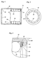
- the bearing has a cylindrical sleeve 10 made of hardened steel, in which is a hollow cylindrical ball cage 12 made of plastic.
- Ball cage 12 balls 14 are held on the inner surface of the sleeve 10 roll and form a rolling bearing for a shaft, not shown, by the Inside of the ball cage 12 passes.
- the length of the ball cage 12 corresponds about half the length of the sleeve 10 so that the ball cage is in Can move axially in the sleeve.
- the sleeve 10 is at both ends provided with inwardly projecting flanged edges 16, the axial Limit the range of motion of the ball cage.
- the wall of the ball cage 12 is axially extending over its entire circumference Provided slots 18, each of which receive several of the balls 14.
- the slots 18 are at one end of the ball cage, left in the figure 1, by a continuous collar 20 on the inner circumference of the ball cage and at the opposite end by a continuous collar 22 on limited outer circumference of the ball cage. This allows the ball cage 12 including the slots 18 in the injection molding process with axially diverging Manufacture molds.
- the slots 18 have one Cross-section that extends radially both inwards and outwards constricted on the outside so that the balls 14 are held in position in a form-fitting manner.
- the hollow cylindrical ball cage 12 is on one Place its circumference through a longitudinal slot 24 interrupted. This allows the ball cage to be compressed elastically. This makes it possible to determine the outside diameter of the ball cage temporarily reduce to the extent that it is caused by the flare 16 limited narrow opening of the sleeve 10 into the sleeve can be introduced.
- the ball cage 12 is preferably in the unloaded state somewhat expanded so that it springs back elastically after insertion into the sleeve 10 and then with a slight preload on the inner surface of the sleeve is present.
- the flared edges jump 16 somewhat in the axial direction back into the interior of the sleeve 10.
- the angle a, around which the flanged edge 16 is angled with respect to the jacket of the sleeve 10 is about 105 ° in the example shown.
- the inner surface 26 of the flange edge consequently forms an outer cone.
- the contact with this outer cone End of the ball cage 12, especially the end face of the collar 22, forms an inner cone 28 complementary to the outer cone. If the Ball cage 12 strikes the flanged edge 16, thus causing the conical Inner surface 26 of the flange edge and the inner cone 28 an expansion the ball cage, that is, a widening of the slot 24. On this The ball cage is securely retained in the sleeve 10.
- the flange edges 16 have at both ends of the sleeve 10 the same shape, and also the end face of the ball cage 12 outside of the federal government 20 forms an inner cone (interrupted by the slots 18) 28.
- the sleeve 10 has an outer diameter of 23 mm and a wall thickness of 1.0 mm.
- the inside diameter the openings delimited by the flange edges 16 is in this Case 19.5 mm.
- the protrusion length by which the flange 16 from the inner surface the sleeve 10 projects, is thus only 0.75 mm. Due to the Angling the flanged edge by more than 90 ° and the inner cone 28 this is sufficient for the ball cage to hold the ball cage securely in position.
- the bearing can be manufactured in a rational way by first the sleeve 10 at both ends with the flanged edges 16 and then is hardened as a whole. Then the ball cage equipped with the balls 14 temporarily compressed using slot 24 and through one of the narrowed ends of the sleeve 10 into the Clip in sleeve.
- the width of the slots 24 is shown somewhat exaggerated in Figure 2.
- the slot is dimensioned so that the outer diameter of the ball cage is then even greater than that delimited by the flange edges 16 Opening when the slot 24 is completely closed and the ends of the Butt the wall of the ball cage.
- Ball cage 12 may also be provided, for example, a needle cage.
Landscapes
- Engineering & Computer Science (AREA)
- General Engineering & Computer Science (AREA)
- Mechanical Engineering (AREA)
- Rolling Contact Bearings (AREA)
- Pens And Brushes (AREA)
- Clamps And Clips (AREA)
- Steroid Compounds (AREA)
Claims (4)
- Palier comprenant un manchon cylindrique (10) en acier trempé rabattu vers l'intérieur à au moins une extrémité et une cage à corps de révolution (12) en matière plastique qui est clipsée dans le manchon et qui possède la forme d'un cylindre creux à fente longitudinale, caractérisé en ce que le bord rabattu (16) à au moins une extrémité du manchon (10) est coudé à plus de 90° par rapport à la surface périphérique de ce dernier, et en ce que l'extrémité correspondante de la cage (12) forme, au moins dans la zone circonférentielle extérieure, un cône intérieur (28).
- Palier selon la revendication 1, caractérisé en ce que les bords rabattus (16) aux deux extrémités du manchon (10) sont coudés à plus de 90°, et les deux extrémités de la cage (12) comportent un cône intérieur (28).
- Palier selon la revendication 1 ou 2, caractérisé en ce que le bord rabattu (16) forme, avec le prolongement de la surface périphérique du manchon (10), un angle compris entre 100° et 110°.
- Palier selon une des revendications précédentes, caractérisé en ce que la longueur de débordement du bord rabattu (16) par rapport à la face intérieure de la surface périphérique du manchon (10) est inférieure à 1,5 mm, de préférence inférieure à 0,8 mm.
Priority Applications (4)
| Application Number | Priority Date | Filing Date | Title |
|---|---|---|---|
| DE59604955T DE59604955D1 (de) | 1996-01-17 | 1996-01-17 | Lager |
| EP96100619A EP0785367B1 (fr) | 1996-01-17 | 1996-01-17 | Palier |
| AT96100619T ATE191775T1 (de) | 1996-01-17 | 1996-01-17 | Lager |
| ES96100619T ES2144652T3 (es) | 1996-01-17 | 1996-01-17 | Rodamiento. |
Applications Claiming Priority (1)
| Application Number | Priority Date | Filing Date | Title |
|---|---|---|---|
| EP96100619A EP0785367B1 (fr) | 1996-01-17 | 1996-01-17 | Palier |
Publications (2)
| Publication Number | Publication Date |
|---|---|
| EP0785367A1 EP0785367A1 (fr) | 1997-07-23 |
| EP0785367B1 true EP0785367B1 (fr) | 2000-04-12 |
Family
ID=8222411
Family Applications (1)
| Application Number | Title | Priority Date | Filing Date |
|---|---|---|---|
| EP96100619A Expired - Lifetime EP0785367B1 (fr) | 1996-01-17 | 1996-01-17 | Palier |
Country Status (4)
| Country | Link |
|---|---|
| EP (1) | EP0785367B1 (fr) |
| AT (1) | ATE191775T1 (fr) |
| DE (1) | DE59604955D1 (fr) |
| ES (1) | ES2144652T3 (fr) |
Families Citing this family (1)
| Publication number | Priority date | Publication date | Assignee | Title |
|---|---|---|---|---|
| DE102007054407A1 (de) * | 2007-11-13 | 2009-05-20 | Ab Skf | Linearwälzlagerkäfig |
Family Cites Families (5)
| Publication number | Priority date | Publication date | Assignee | Title |
|---|---|---|---|---|
| DE1068955B (fr) * | 1959-11-12 | |||
| DE959699C (de) * | 1953-04-14 | 1957-03-07 | Duerkoppwerke Ag | Einteiliger Kunststoff-Rollenkaefig, insbesondere Nadelrollenkaefig |
| FR2066169A5 (fr) * | 1969-10-18 | 1971-08-06 | Schaeffler Ohg Industriewerk | |
| DE7321955U (de) * | 1973-06-13 | 1973-09-06 | Skf Kugellagerfabriken Gmbh | Lager fuer geringe axialbewegungen |
| US4492415A (en) * | 1982-03-03 | 1985-01-08 | Skf Industries, Inc. | Unitary full complement bearing components containing rolling elements in a self-supporting lubricating matrix |
-
1996
- 1996-01-17 EP EP96100619A patent/EP0785367B1/fr not_active Expired - Lifetime
- 1996-01-17 DE DE59604955T patent/DE59604955D1/de not_active Expired - Fee Related
- 1996-01-17 ES ES96100619T patent/ES2144652T3/es not_active Expired - Lifetime
- 1996-01-17 AT AT96100619T patent/ATE191775T1/de not_active IP Right Cessation
Also Published As
| Publication number | Publication date |
|---|---|
| ES2144652T3 (es) | 2000-06-16 |
| DE59604955D1 (de) | 2000-05-18 |
| EP0785367A1 (fr) | 1997-07-23 |
| ATE191775T1 (de) | 2000-04-15 |
Similar Documents
| Publication | Publication Date | Title |
|---|---|---|
| EP2129925B1 (fr) | Cage axiale en plusieurs parties pour un palier à roulement de grande dimension | |
| EP0582543B1 (fr) | Dispositif de raccordement de tuyaux | |
| DE3025705C2 (fr) | ||
| DE2553290A1 (de) | Hydrodynamische wellendichtung, und verfahren zu ihrer herstellung | |
| EP0505719A1 (fr) | Articulation à rotule | |
| DE3902194A1 (de) | Radial-waelzlager | |
| WO1994012800A1 (fr) | Coussinet enroule | |
| DE2518129A1 (de) | Duennwandiger laufring bzw. laufscheibe fuer ein kugellager, daraus hergestelltes kugellager sowie verfahren und vorrichtung zu deren herstellung | |
| DE102019127287B4 (de) | Zweiteiliger Lagerkäfig sowie Wälzlager mit einem solchen Lagerkäfig | |
| DE69703347T2 (de) | Übertragungsgelenkkreuz und entsprechendes übertragungsgelenk | |
| DE2420264A1 (de) | Kunststofflager aus spritzguss | |
| DE3527423A1 (de) | Elektromagnet | |
| DE19929536C1 (de) | Anordnung zur axialen Festlegung des Ringes eines Lagers | |
| DE2120905B2 (de) | Längsführungslager | |
| DE102015103405A1 (de) | Synchronring für eine Synchronisationseinheit eines Schaltgetriebes | |
| DE3146849C2 (de) | Lageranordnung für Längs- und Drehbewegungen einer Welle | |
| DE4420487C1 (de) | Hohlzapfengelenk | |
| DE1575102A1 (de) | Anordnung zur Verminderung einer Durchwoelbung eines geschlitzten Federring-Halteglieds | |
| EP0285818B1 (fr) | Tourillon à autoréglage avec jeu axial pour véhicules à moteur | |
| DE1525291B2 (de) | Verfahren und vorrichtung zum kaltwalzen von profilierten lagerringen | |
| EP0785367A1 (fr) | Douille palier | |
| DE2536658A1 (de) | Kugellager fuer laengsbewegungen | |
| DE1141141B (de) | Auf seinen Traeger unter Spannung aufgezogener innerer Laufring fuer Nadel- oder Rollenlager | |
| DE2831183A1 (de) | Vollrolliges waelzlager | |
| DE10221438B4 (de) | Faltenbalgkappe mit Preßsitz |
Legal Events
| Date | Code | Title | Description |
|---|---|---|---|
| PUAI | Public reference made under article 153(3) epc to a published international application that has entered the european phase |
Free format text: ORIGINAL CODE: 0009012 |
|
| 17P | Request for examination filed |
Effective date: 19960724 |
|
| AK | Designated contracting states |
Kind code of ref document: A1 Designated state(s): AT BE CH DE DK ES FR GB GR IE IT LI LU MC NL PT SE |
|
| GRAG | Despatch of communication of intention to grant |
Free format text: ORIGINAL CODE: EPIDOS AGRA |
|
| 17Q | First examination report despatched |
Effective date: 19990318 |
|
| GRAG | Despatch of communication of intention to grant |
Free format text: ORIGINAL CODE: EPIDOS AGRA |
|
| GRAH | Despatch of communication of intention to grant a patent |
Free format text: ORIGINAL CODE: EPIDOS IGRA |
|
| GRAH | Despatch of communication of intention to grant a patent |
Free format text: ORIGINAL CODE: EPIDOS IGRA |
|
| GRAA | (expected) grant |
Free format text: ORIGINAL CODE: 0009210 |
|
| ITF | It: translation for a ep patent filed | ||
| AK | Designated contracting states |
Kind code of ref document: B1 Designated state(s): AT BE CH DE DK ES FR GB GR IE IT LI LU MC NL PT SE |
|
| PG25 | Lapsed in a contracting state [announced via postgrant information from national office to epo] |
Ref country code: NL Free format text: LAPSE BECAUSE OF FAILURE TO SUBMIT A TRANSLATION OF THE DESCRIPTION OR TO PAY THE FEE WITHIN THE PRESCRIBED TIME-LIMIT Effective date: 20000412 |
|
| REF | Corresponds to: |
Ref document number: 191775 Country of ref document: AT Date of ref document: 20000415 Kind code of ref document: T |
|
| REG | Reference to a national code |
Ref country code: CH Ref legal event code: EP |
|
| GBT | Gb: translation of ep patent filed (gb section 77(6)(a)/1977) |
Effective date: 20000413 |
|
| REF | Corresponds to: |
Ref document number: 59604955 Country of ref document: DE Date of ref document: 20000518 |
|
| REG | Reference to a national code |
Ref country code: IE Ref legal event code: FG4D Free format text: GERMAN |
|
| REG | Reference to a national code |
Ref country code: ES Ref legal event code: FG2A Ref document number: 2144652 Country of ref document: ES Kind code of ref document: T3 |
|
| PG25 | Lapsed in a contracting state [announced via postgrant information from national office to epo] |
Ref country code: PT Free format text: LAPSE BECAUSE OF FAILURE TO SUBMIT A TRANSLATION OF THE DESCRIPTION OR TO PAY THE FEE WITHIN THE PRESCRIBED TIME-LIMIT Effective date: 20000712 Ref country code: DK Free format text: LAPSE BECAUSE OF FAILURE TO SUBMIT A TRANSLATION OF THE DESCRIPTION OR TO PAY THE FEE WITHIN THE PRESCRIBED TIME-LIMIT Effective date: 20000712 |
|
| PG25 | Lapsed in a contracting state [announced via postgrant information from national office to epo] |
Ref country code: GR Free format text: LAPSE BECAUSE OF FAILURE TO SUBMIT A TRANSLATION OF THE DESCRIPTION OR TO PAY THE FEE WITHIN THE PRESCRIBED TIME-LIMIT Effective date: 20000714 |
|
| ET | Fr: translation filed | ||
| NLV1 | Nl: lapsed or annulled due to failure to fulfill the requirements of art. 29p and 29m of the patents act | ||
| PG25 | Lapsed in a contracting state [announced via postgrant information from national office to epo] |
Ref country code: IE Free format text: LAPSE BECAUSE OF NON-PAYMENT OF DUE FEES Effective date: 20010109 |
|
| PG25 | Lapsed in a contracting state [announced via postgrant information from national office to epo] |
Ref country code: LU Free format text: LAPSE BECAUSE OF NON-PAYMENT OF DUE FEES Effective date: 20010117 Ref country code: GB Free format text: LAPSE BECAUSE OF NON-PAYMENT OF DUE FEES Effective date: 20010117 Ref country code: AT Free format text: LAPSE BECAUSE OF NON-PAYMENT OF DUE FEES Effective date: 20010117 |
|
| PG25 | Lapsed in a contracting state [announced via postgrant information from national office to epo] |
Ref country code: SE Free format text: LAPSE BECAUSE OF NON-PAYMENT OF DUE FEES Effective date: 20010118 Ref country code: ES Free format text: LAPSE BECAUSE OF NON-PAYMENT OF DUE FEES Effective date: 20010118 |
|
| PG25 | Lapsed in a contracting state [announced via postgrant information from national office to epo] |
Ref country code: MC Free format text: LAPSE BECAUSE OF NON-PAYMENT OF DUE FEES Effective date: 20010131 Ref country code: LI Free format text: LAPSE BECAUSE OF NON-PAYMENT OF DUE FEES Effective date: 20010131 Ref country code: CH Free format text: LAPSE BECAUSE OF NON-PAYMENT OF DUE FEES Effective date: 20010131 Ref country code: BE Free format text: LAPSE BECAUSE OF NON-PAYMENT OF DUE FEES Effective date: 20010131 |
|
| PLBE | No opposition filed within time limit |
Free format text: ORIGINAL CODE: 0009261 |
|
| STAA | Information on the status of an ep patent application or granted ep patent |
Free format text: STATUS: NO OPPOSITION FILED WITHIN TIME LIMIT |
|
| 26N | No opposition filed | ||
| BERE | Be: lapsed |
Owner name: SCHWARZBICH JORG Effective date: 20010131 |
|
| GBPC | Gb: european patent ceased through non-payment of renewal fee |
Effective date: 20010117 |
|
| EUG | Se: european patent has lapsed |
Ref document number: 96100619.4 |
|
| REG | Reference to a national code |
Ref country code: CH Ref legal event code: PL |
|
| PG25 | Lapsed in a contracting state [announced via postgrant information from national office to epo] |
Ref country code: FR Free format text: LAPSE BECAUSE OF NON-PAYMENT OF DUE FEES Effective date: 20010928 |
|
| PG25 | Lapsed in a contracting state [announced via postgrant information from national office to epo] |
Ref country code: DE Free format text: LAPSE BECAUSE OF NON-PAYMENT OF DUE FEES Effective date: 20011101 |
|
| REG | Reference to a national code |
Ref country code: FR Ref legal event code: ST |
|
| REG | Reference to a national code |
Ref country code: ES Ref legal event code: FD2A Effective date: 20020211 |
|
| PG25 | Lapsed in a contracting state [announced via postgrant information from national office to epo] |
Ref country code: IT Free format text: LAPSE BECAUSE OF NON-PAYMENT OF DUE FEES;WARNING: LAPSES OF ITALIAN PATENTS WITH EFFECTIVE DATE BEFORE 2007 MAY HAVE OCCURRED AT ANY TIME BEFORE 2007. THE CORRECT EFFECTIVE DATE MAY BE DIFFERENT FROM THE ONE RECORDED. Effective date: 20050117 |