EP0785337A2 - Dispositif pour contenir un agent de soutènement et procédés pour son utilisation - Google Patents
Dispositif pour contenir un agent de soutènement et procédés pour son utilisation Download PDFInfo
- Publication number
- EP0785337A2 EP0785337A2 EP97300253A EP97300253A EP0785337A2 EP 0785337 A2 EP0785337 A2 EP 0785337A2 EP 97300253 A EP97300253 A EP 97300253A EP 97300253 A EP97300253 A EP 97300253A EP 0785337 A2 EP0785337 A2 EP 0785337A2
- Authority
- EP
- European Patent Office
- Prior art keywords
- tubular structure
- flow passage
- slurry
- tubular
- axially
- Prior art date
- Legal status (The legal status is an assumption and is not a legal conclusion. Google has not performed a legal analysis and makes no representation as to the accuracy of the status listed.)
- Withdrawn
Links
- 238000000034 method Methods 0.000 title claims description 29
- 239000002002 slurry Substances 0.000 claims abstract description 89
- 239000012530 fluid Substances 0.000 claims description 60
- 238000004891 communication Methods 0.000 claims description 41
- 239000002245 particle Substances 0.000 claims description 22
- 238000007789 sealing Methods 0.000 claims description 19
- 230000002093 peripheral effect Effects 0.000 claims description 16
- 238000001914 filtration Methods 0.000 claims description 11
- 239000000463 material Substances 0.000 claims description 11
- 238000011144 upstream manufacturing Methods 0.000 claims description 4
- 238000007373 indentation Methods 0.000 claims description 3
- 230000000717 retained effect Effects 0.000 claims description 3
- 230000003628 erosive effect Effects 0.000 claims description 2
- 230000015572 biosynthetic process Effects 0.000 description 30
- 238000005755 formation reaction Methods 0.000 description 30
- 230000001681 protective effect Effects 0.000 description 11
- 230000035699 permeability Effects 0.000 description 8
- 239000004576 sand Substances 0.000 description 8
- 230000008859 change Effects 0.000 description 6
- 238000005299 abrasion Methods 0.000 description 5
- 230000008878 coupling Effects 0.000 description 5
- 238000010168 coupling process Methods 0.000 description 5
- 238000005859 coupling reaction Methods 0.000 description 5
- 239000011148 porous material Substances 0.000 description 4
- 239000002184 metal Substances 0.000 description 3
- 229910052751 metal Inorganic materials 0.000 description 3
- 238000012216 screening Methods 0.000 description 3
- 230000008901 benefit Effects 0.000 description 2
- 238000005553 drilling Methods 0.000 description 2
- 239000000203 mixture Substances 0.000 description 2
- 229910000851 Alloy steel Inorganic materials 0.000 description 1
- 229910000967 As alloy Inorganic materials 0.000 description 1
- 229910000831 Steel Inorganic materials 0.000 description 1
- 238000007796 conventional method Methods 0.000 description 1
- 239000000499 gel Substances 0.000 description 1
- 229930195733 hydrocarbon Natural products 0.000 description 1
- 150000002430 hydrocarbons Chemical class 0.000 description 1
- 239000007769 metal material Substances 0.000 description 1
- 238000005121 nitriding Methods 0.000 description 1
- 239000003129 oil well Substances 0.000 description 1
- 238000012856 packing Methods 0.000 description 1
- 239000011236 particulate material Substances 0.000 description 1
- 230000008569 process Effects 0.000 description 1
- 238000005086 pumping Methods 0.000 description 1
- 238000011160 research Methods 0.000 description 1
- 239000010959 steel Substances 0.000 description 1
- 230000007704 transition Effects 0.000 description 1
- UONOETXJSWQNOL-UHFFFAOYSA-N tungsten carbide Chemical compound [W+]#[C-] UONOETXJSWQNOL-UHFFFAOYSA-N 0.000 description 1
- 238000003466 welding Methods 0.000 description 1
Images
Classifications
-
- E—FIXED CONSTRUCTIONS
- E21—EARTH OR ROCK DRILLING; MINING
- E21B—EARTH OR ROCK DRILLING; OBTAINING OIL, GAS, WATER, SOLUBLE OR MELTABLE MATERIALS OR A SLURRY OF MINERALS FROM WELLS
- E21B43/00—Methods or apparatus for obtaining oil, gas, water, soluble or meltable materials or a slurry of minerals from wells
- E21B43/02—Subsoil filtering
- E21B43/04—Gravelling of wells
- E21B43/045—Crossover tools
-
- E—FIXED CONSTRUCTIONS
- E21—EARTH OR ROCK DRILLING; MINING
- E21B—EARTH OR ROCK DRILLING; OBTAINING OIL, GAS, WATER, SOLUBLE OR MELTABLE MATERIALS OR A SLURRY OF MINERALS FROM WELLS
- E21B27/00—Containers for collecting or depositing substances in boreholes or wells, e.g. bailers, baskets or buckets for collecting mud or sand; Drill bits with means for collecting substances, e.g. valve drill bits
- E21B27/02—Dump bailers, i.e. containers for depositing substances, e.g. cement or acids
-
- E—FIXED CONSTRUCTIONS
- E21—EARTH OR ROCK DRILLING; MINING
- E21B—EARTH OR ROCK DRILLING; OBTAINING OIL, GAS, WATER, SOLUBLE OR MELTABLE MATERIALS OR A SLURRY OF MINERALS FROM WELLS
- E21B43/00—Methods or apparatus for obtaining oil, gas, water, soluble or meltable materials or a slurry of minerals from wells
- E21B43/25—Methods for stimulating production
- E21B43/26—Methods for stimulating production by forming crevices or fractures
- E21B43/267—Methods for stimulating production by forming crevices or fractures reinforcing fractures by propping
Definitions
- the present invention relates generally to tools used in subterranean wells and, more particularly but not exclusively, to a proppant containment apparatus for use in formation fracturing operations.
- a potentially productive geological formation beneath the earth's surface contains a sufficient volume of valuable fluids, such as hydrocarbons, but also has a very low permeability.
- Permeability is a term used to describe that quality of a geological formation which enables fluids to move about in the formation. All potentially productive formations have pores, a quality described using the term “porosity”, within which the valuable fluids are contained. If, however, the pores are not interconnected, the fluids cannot move about and, thus, cannot be brought to the earth's surface.
- the low permeability of the formation may only exist near the wellbore (e.g. when the low permeability was caused by drilling muds and completion fluids), in which case it is only necessary to artificially increase the formation's permeability near the wellbore. In either case, this is typically accomplished by "fracturing" the formation, a practice which is well known in the art and for which purpose many methods have been conceived. Basically, fracturing is achieved by applying sufficient pressure to the formation to cause the formation to crack or fracture, hence the name, the desired result being that the cracks interconnect the formation's pores and allow the valuable fluids to be brought out of the formation and to the surface.
- a conventional method of fracturing a formation begins with drilling a subterranean well into the formation and cementing a protective tubular casing within the well. The casing is then perforated to provide fluid communication between the formation and the interior of the casing which extends to the surface.
- a packer is set in the casing to isolate the formation from the rest of the wellbore, and hydraulic pressure is applied to the formation via tubing which extends from the packer to pumps on the surface.
- the pumps apply the hydraulic pressure by pumping fracturing fluid down the tubing, through the packer, through a service tool assembly, into the wellbore below the packer, through the perforations, and finally, into the formation.
- the pressure is increased until the desired quality and quantity of cracks is achieved.
- Much research has gone into discerning the precise amount and rate of fracturing fluid and hydraulic pressure to apply to the formation to achieve the desired quality and quantity of cracks.
- the fracturing fluid's composition is far from a simple matter itself.
- Modem fracturing fluids may include sophisticated man-made proppants suspended in gels.
- Propppant is the term used to describe material in the fracturing fluid which enters the formation cracks once formed and while the hydraulic pressure is still being applied (that is, while the cracks are still being held open by the hydraulic pressure), and acts to prop the cracks open. When the hydraulic pressure is removed, the proppant keeps the cracks from closing completely. The proppant thus helps to maintain the artificial permeability of the formation after the fracturing job is over.
- Fracturing fluid containing suspended proppant is also called a slurry.
- a proppant may be nothing more than a very fine sand, or it may be a particulate material specifically engineered for the job of holding formation cracks open. Whatever its composition, the proppant must be very hard and strong to withstand the forces trying to close the formation cracks. These qualities also make the proppant a very good abrasive. It is not uncommon for holes to be formed in the protective casing, tubing, pumps, and any other equipment through which a slurry is pumped.
- Particularly susceptible to abrasion wear from pumped slurry is any piece of equipment in which the slurry must make a sudden or significant change in direction.
- the slurry being governed by the laws of physics, including the principles of inertia, tends to maintain its velocity and direction of flow, and resists any change thereof.
- An object in the flowpath of the slurry which tends to change the velocity or direction of the slurry's flow will soon be worn away as the proppant in the slurry inceimpulsly impinges upon the object.
- a piece of equipment attached to the tubing extending below the packer which takes the slurry as it is pumped down the tubing and redirects it radially outward so that it exits the tubing and enters the formation through the perforations.
- That piece of equipment is known to those skilled in the art as a crossover. Assuming, for purposes of convenience, that the tubing extends vertically through the wellbore, and that the formation is generally horizontal, the crossover must change the direction of the slurry by ninety degrees. Because of this significant change of direction, few pieces of equipment (with the notable exception of the pumps) must withstand as much potential abrasive wear as the crossover.
- the crossover is frequently called upon to do several other tasks while the slurry is being pumped through it.
- the crossover typically contains longitudinal circulation ports through which fracturing fluids that are not received into the formation after exiting the crossover are transmitted back to the surface.
- Space limitations in the wellbore dictate that the circulation ports are not far removed from the flowpath of the slurry through the crossover. If the crossover is worn away such that the slurry flowpath achieves fluid communication with the circulation ports in the crossover, the fracturing job must cease while the tubing is removed from the wellbore to replace the crossover at great loss of time and money. Otherwise, the slurry will enter the circulation ports in the crossover and the proppant will fill the tubing below the crossover, any screens attached thereto, and possibly stick the tool in the well. This latter situation is usually the result of a failed crossover, since operators at the earth's surface do not usually know that the crossover has been worn away.
- the crossover has commonly been considered a critical piece of equipment, whose failure during slurry delivery usually means failure of the entire fracturing job.
- Extensive measures have been employed in the past to avoid failure of the crossover, that is, to retard abrasive wear of the crossover and the resultant communication between the slurry flowpath and circulation ports. None, however, have solved the problem of how to continue a fracturing job even after the crossover has failed.
- the present invention provides a proppant containment apparatus operatively positionable in a subterranean wellbore, said apparatus comprising: first and second tubular members, each of said first and second tubular members having first and second opposite ends, said first tubular member second opposite end being coaxially attached to said second tubular member first opposite end, said second tubular member having first and second internal surfaces and said first tubular member having a third internal surface, said first internal surface being adjacent said second tubular member first opposite end and said first tubular member second opposite end, and said first internal surface being radially outwardly disposed relative to each of said second and third internal surfaces; and a screen disposed within said second tubular member radially inward relative to said first internal surface, said screen having an outer peripheral edge portion, said outer peripheral edge portion being disposed radially outward relative to each of said second and third internal surfaces, such that said screen is retained axially intermediate said second and third internal surfaces.
- the apparatus further comprises a third tubular member having first and second opposite ends and fourth, fifth and sixth internal surfaces formed therein, said third tubular member first opposite end being attached to said second tubular member second opposite end such that said second internal surface is in fluid communication with said fourth internal surface, said fifth internal surface being disposed axially intermediate said fourth and sixth internal surfaces and having a ball sealing surface formed thereon; and a ball disposed axially intermediate said screen and said ball sealing surface, said ball being capable of sealingly engaging said ball sealing surface, such that, a fluid flow directed from said first tubular member first opposite end to said third tubular member second opposite end biases said ball to sealingly engage said ball sealing surface.
- said fifth internal surface further has a groove formed thereon, said groove permitting fluid communication between said fourth internal surface and said sixth internal surface when said ball sealingly engages said ball sealing surface.
- the apparatus may further comprise a fourth tubular member having a first internal flow passage through which a pressurized, abrasive slurry material may be axially flowed, an axial portion having a side wall section with an outlet opening therein through which said slurry material may be outwardly discharged from said first internal flow passage, and a second internal flow passage formed axially through said side wall section, said fourth tubular member being attached to said first tubular member first opposite end, said second internal flow passage being in fluid communication with said third internal surface and said outlet opening being in fluid communication with said second internal surface.
- the invention provides proppant containment apparatus operatively positionable in a subterranean wellbore, said apparatus comprising: a perforated pipe having an axially extending internal flow passage, an external side surface, first and second opposite ends, and an opening formed on an axial portion of said perforated pipe, said internal flow passage being closed at said first opposite end and open at said second opposite end; a screen radially outwardly overlying said opening, said screen being attached to said perforated pipe external side surface intermediate said perforated pipe first and second opposite ends; a generally tubular structure having an internal side surface, said tubular structure radially outwardly overlying said perforated pipe; an annular flow passage formed radially intermediate said perforated pipe external side surface and said tubular structure internal side surface, said screen being disposed in said annular flow passage; and an annular seal member disposed in said annular flow passage and sealingly engaging said perforated pipe external side surface and said tubular structure internal side surface, said opening being disposed axially intermediate said perfor
- the apparatus of this aspect may preferably further comprise a fluid passage formed across said ball sealing surface, said fluid passage permitting fluid communication across said ball sealing surface when said ball sealingly engages said ball sealing surface.
- the apparatus may also further comprise a crossover attached to said perforated pipe and said tubular structure, said crossover having formed therein an axially extending circulation port, an axially extending slurry passage, and a radially outwardly directed slurry port, said slurry passage and said slurry port being in fluid communication with each other, and said circulation port being in fluid communication with said annular flow passage adjacent said perforated pipe first opposite end.
- a crossover attached to said perforated pipe and said tubular structure, said crossover having formed therein an axially extending circulation port, an axially extending slurry passage, and a radially outwardly directed slurry port, said slurry passage and said slurry port being in fluid communication with each other, and said circulation port being in fluid communication with said annular flow passage adjacent said perforated pipe first opposite end.
- the screen is preferably a welded tubular sand screen.
- the invention provides apparatus operatively positionable in a subterranean wellbore for containing particles delivered to the wellbore in a slurry, which apparatus comprises: a first tubular member having first and second opposite ends, and an internal coaxial flow passage formed therein through which the slurry may be flowed, said internal flow passage extending from said first opposite end to said second opposite end; a screen disposed in said first tubular member internal flow passage, said screen being capable of filtering the particles from the slurry; a seal structure attached to said first tubular member second opposite end, said seal structure having a seal surface disposed therein, said seal surface being in fluid communication with said internal flow passage and having an indentation formed thereon; and a seal member disposed intermediate said screen and said seal surface, said seal member being biased to sealingly engage said seal surface when the slurry flows from said screen to said seal structure.
- the apparatus of this further aspect may further comprise a second tubular member coaxially attached to, and extending outwardly from, said first tubular member first opposite end, said second tubular member having an internal flow passage formed therein which is in fluid communication with said first tubular member internal flow passage, and said screen being disposed intermediate said first tubular member internal flow passage and said second tubular member internal flow passage.
- the screen is preferably compressed between said first tubular member and said second tubular member when said first tubular member is attached to said second tubular member.
- the apparatus of this further aspect may further comprise a second tubular member disposed within said first tubular member, said second tubular member having a plurality of radial perforations formed thereon and an internal flow passage, said first tubular member internal flow passage being in fluid communication with said second tubular member internal flow passage through said perforations, and said screen being disposed intermediate said perforations and said first tubular member internal flow passage.
- the invention also includes apparatus operatively positionable in a subterranean wellbore during pressurized proppant slurry delivery into the wellbore, which apparatus comprises: a first tubular structure having a first internal flow passage through which the proppant slurry may be axially flowed in a downstream direction, an axial portion having a sidewall section with a circumferentially spaced plurality of axially elongated first outlet slots disposed therein and through which the proppant slurry may be outwardly discharged from said internal flow passage, each of said first outlet slots being circumscribed by a peripheral edge portion of said side wall section, and a circumferentially spaced plurality of axially elongated circulation ports formed in said side wall section intermediate said first outlet slots and through which the proppant slurry may be axially flowed in an upstream direction; a second tubular structure coaxially mounted to said first tubular structure radially outwardly from said circulation ports and extending outwardly from said first tubular structure in said
- the fourth tubular structure has first and second opposite ends, said third tubular structure openings being disposed axially intermediate said fourth tubular structure first and second opposite ends.
- Each of said fourth tubular structure first and second opposite ends are preferably circumferentially sealed to an outer side surface of said third tubular structure.
- the groove permits fluid communication across said sloping surface when said ball sealingly engages said sloping surface.
- the apparatus may further comprise a fifth tubular structure attached to said second tubular structure, said fifth tubular structure having said sloping surface formed therein and an axially extending second internal flow passage, said sloping surface being intermediate said second internal flow passage and said seal member, and said second internal flow passage being in fluid communication with said circulation ports in said first tubular structure.
- the invention further includes a method of containing abrasive particles in an abrasive slurry delivery structure having a first tubular structure with an internal flow passage through which the abrasive slurry is axially flowed, a side wall outlet opening bounded by a peripheral side wall edge portion and outwardly through which the abrasive slurry material from the internal flow passage is discharged, and an internal circulation passage formed adjacent the peripheral side wall edge portion, wherein the abrasive particles are contained in the internal circulation passage after slurry erosion of the peripheral side wall edge portion, the method comprising the steps of: providing a second tubular structure having first and second opposite ends, and an internal flow passage formed therein through which the slurry may be flowed; attaching said second tubular structure first opposite end to said first tubular structure such that the internal circulation passage is in fluid communication with said second tubular structure internal flow passage; providing a screen capable of filtering the abrasive particles from the slurry; and disposing said screen in said second tubular structure
- the above method preferably further comprises the steps of: providing a seal structure having a seal surface disposed therein; attaching said seal structure to said second tubular structure second opposite end such that said seal surface is in fluid communication with said second tubular structure internal flow passage; providing a seal member capable of sealingly engaging said seal surface; and disposing said seal member in said second tubular structure internal flow passage intermediate said screen and said seal surface such that slurry flow from said screen to said seal member biases said seal member to sealingly engage said seal surface.
- the method may further comprise the step of forming a fluid passage on said seal surface such that fluid communication remains across said seal surface when said seal member is biased to sealingly engage said seal surface.
- the method may further comprise the steps of: providing a third tubular structure having an internal flow passage formed therein; disposing said screen intermediate said third tubular structure internal flow passage and said second tubular structure internal flow passage; attaching said third tubular structure intermediate said first tubular structure and said second tubular structure such that said third tubular structure internal flow passage is in fluid communication with the internal circulation passage and said second tubular structure internal flow passage; and compressing said screen between said second and third tubular structures.
- the screen providing step may further comprise providing said screen made of a sintered metal material.
- the above method may further comprise the steps of: providing a third tubular structure having a perforated axial portion and an internal flow passage formed therein; disposing said third tubular structure in said second tubular structure internal flow passage such that said second tubular structure internal flow passage is in fluid communication with said third tubular structure internal flow passage through said perforated axial portion; and disposing said screen adjacent said perforated axial portion and intermediate said second tubular structure internal flow passage and said third tubular structure internal flow passage.
- the screen providing step may further comprise providing a tubular welded sand screen.
- the invention also provides a further method of containing proppant delivered to a subterranean wellbore in a slurry, the method comprising the steps of: providing a first tubular structure having a first internal flow passage through which the slurry may be flowed, an axial portion having a sidewall section with an outlet slot disposed therein and through which the slurry may be outwardly discharged from said internal flow passage, said outlet slot being circumscribed by a peripheral edge portion of said side wall section, and an axially elongated circulation port formed in said side wall section; providing a second tubular structure; coaxially mounting said second tubular structure to said first tubular structure radially outward from said circulation port and extending axially outward from said first tubular structure; providing a screen capable of filtering the proppant from the slurry; mounting said screen in said second tubular structure; providing a radially inwardly sloping surface; mounting said inwardly sloping surface to said second tubular structure; providing a ball capable of
- This further method preferably comprises the steps of: providing a third tubular structure having an inner side surface, a plurality of openings formed radially therethrough, and opposite open and closed ends; coaxially disposing said third tubular structure within said second tubular structure and defining an annular gap between said second tubular structure and said third tubular structure, said closed end being mounted to said first tubular structure radially inwardly from said circulation ports, such that said circulation ports are in fluid communication with said annular gap; providing a seal member; sealing off said annular gap between said second and third tubular structures with said seal member, and wherein said screen providing step comprises providing a fourth tubular structure having first and second opposite ends, and wherein said screen mounting step comprises coaxially disposing said fourth tubular structure within said annular gap axially intermediate said first tubular structure and said seal member and radially outwardly adjacent said third tubular structure openings, such that said third tubular structure openings are disposed axially intermediate said fourth tubular structure first and second opposite ends.
- the method may include the step of circumferentially sealing each of said fourth tubular structure first and second opposite ends to an outer side surface of said third tubular structure.
- a step of forming a groove on said sloping surface may be included to permit fluid communication across said sloping surface when said ball sealingly engages said sloping surface.
- the further method of the invention may also comprises the steps of: providing a third tubular structure having an internal flow passage formed therein; coaxially attaching said third tubular structure intermediate said first and second tubular structures such that said third tubular structure internal flow passage is in fluid communication with said circulation port and an internal flow passage of said second tubular structure, and wherein said screen mounting step comprises disposing said screen intermediate said second tubular structure internal flow passage and said third tubular structure internal flow passage.
- the invention further provides the method of containing abrasive particles in a subterranean wellbore during pressurized particle slurry delivery into the wellbore, the method comprising the steps of: providing a first tubular structure having a first internal flow passage through which the particle slurry may be axially flowed in a downstream direction, an axial portion having a sidewall section with a circumferentially spaced plurality of axially elongated first outlet slots disposed therein and through which the particle slurry may be outwardly discharged from said internal flow passage, each of said first outlet slots being circumscribed by a peripheral edge portion of said side wall section, and a circumferentially spaced plurality of axially elongated circulation ports formed in said side wall section intermediate said first outlet slots and through which the particle slurry may be axially flowed in an upstream direction; providing a plug having an exterior surface; mounting said plug to said first tubular structure downstream of said axial portion, such that said exterior surface of said plug is disposed radi
- said fourth tubular structure providing step further comprises providing said fourth tubular structure having first and second opposite ends, and wherein said fourth tubular structure disposing step further comprises disposing said fourth tubular structure such that said third tubular structure openings are disposed axially intermediate said fourth tubular structure first and second opposite ends.
- the method may further comprise the step of circumferentially sealing each of said fourth tubular structure first and second opposite ends to an outer side surface of said third tubular structure.
- the method may further comprise the step of permitting fluid communication through said groove and across said sloping surface when said ball sealingly engages said sloping surface.
- the method may further comprise the steps of: providing a fifth tubular structure having said sloping surface formed therein and an axially extending second internal flow passage; and attaching said fifth tubular structure to said second tubular structure, such that said second internal flow passage is in fluid communication with said circulation ports in said first tubular structure, said sloping surface is intermediate said second internal flow passage and said third tubular structure, and said ball is intermediate said sloping surface and said third tubular structure.
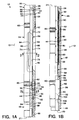
- FIGS. 1A and 1B Illustrated in FIGS. 1A and 1B is a proppant containment apparatus 10 which embodies principles of the present invention.
- a proppant containment apparatus 10 which embodies principles of the present invention.
- directional terms such as "upper”, “lower”, “upward”, “downward”, etc. will be used in relation to the apparatus 10 as it is depicted in the accompanying figures. It is to be understood that the apparatus 10 may be utilized in vertical, horizontal, inverted, or inclined orientations without deviating from the principles of the present invention.
- Apparatus 10 as representatively illustrated in FIGS. 1A and 1B, is specially adapted for use within a tool string known to those skilled in the art as a service tool string (not shown), which is suspended from tubing extending to the earth's surface, the tubing being longitudinally disposed within protective casing in a subterranean wellbore 12.
- a service tool string (not shown)
- the wellbore 12 is external to the apparatus 10.
- the service tool string is typically inserted through a packer (not shown) during a fracturing job.
- a pressurized, abrasive slurry is then pumped through the tubing and into the service tool string.
- Tubular upper connector 14 and lower connector 16 permit interconnection of the apparatus 10 into the service tool string.
- upper portion 18 of upper connector 14 is connected to the service tool string above the apparatus 10
- lower portion 20 of lower connector 16 is connected to the remainder of the service tool string extending below the apparatus 10.
- illustratively cut surface 21 of FIG. 1A is continuous with the same cut surface 21 of FIG. 1B.
- Axial flow passage 22 extends longitudinally (i.e., axially) downward from the upper portion 18 of upper connector 14, axially through the upper connector, and into a generally tubular crossover 24.
- the axial flow passage 22 terminates at upper radially reduced portion 26 of generally cylindrical plug 28.
- Plug 28 is threadedly installed into lower portion 30 of crossover 24 and secured with a pair of set screws 32 (only one of which is visible in FIG. 1A). Sealing engagement between the plug 28 and the lower portion 30 of crossover 24 is provided by seal 34 disposed in circumferential groove 36 externally formed on the plug.
- circulation flow passage 38 extends downwardly from upper portion 18, through the upper connector 14, longitudinally through the crossover 24 in a manner that will be described more fully hereinbelow, through the lower connector 16, and to lower portion 20.
- the circulation flow passage 38 in the apparatus 10 is sealingly isolated from the wellbore 12 external to the apparatus by seal 40 disposed in circumferential groove 42 internally formed on the upper connector 14, by seals 44 disposed in circumferential grooves 46 internally formed on extension subs 48, and by seal 50 disposed in circumferential groove 52 internally formed on the lower connector 16.
- the circulation flow passage 38 is sealingly isolated from axial flow passage 22 in the apparatus 10 by seal 34, and by a pair of seals 54, each disposed in one of a pair of circumferential grooves 56 externally formed on an upper portion 58 of the crossover 24 which is threadedly installed coaxially into the upper connector 14.
- the proppant slurry is pumped downwardly through the longitudinal flow passage 22, radially outward through the crossover 24 and into the wellbore 12, and outwardly into the geological formation being fractured and/or gravel packed (not shown).
- the fluid portion of the proppant slurry (minus the proppant) which is not retained in the formation is returned to the earth's surface through the circulation flow passage 38.
- the normal direction of flow in the circulation flow passage 38 is longitudinally upward as viewed in FIGS. 1A and 1B, with no proppant in the flow.
- Annular seal rings 60 are disposed in longitudinally spaced apart external annular recesses 62 formed between upper connector 14 and upper portion 58 of crossover 24, between lower portion 30 of crossover 24 and the representatively illustrated upper extension sub 48, between the extension subs 48, and between the representatively illustrated lower extension sub 48 and lower connector 16.
- the seal rings 60 seal the apparatus 10 within the packer and other equipment into which the apparatus 10 may be longitudinally disposed.
- exit ports 64 Four longitudinally extending circumferentially spaced apart slotted outlet openings or exit ports 64 (three of which are visible in FIG. lA), having external radially extending and circumferentially sloping surfaces 66 formed thereon, provide fluid communication between the axial flow passage 22 and the wellbore 12. It is through these exit ports 64 that a slurry must pass in its transition from longitudinal flow in the axial flow passage 22 to radial flow into the wellbore 12. Because of the substantial change of direction from longitudinal flow to radial flow of the slurry through the exit ports 64, the exit ports are particularly susceptible to abrasion wear from proppant contained in the slurry.
- a tubular protective sleeve 68 is coaxially disposed within the crossover 24.
- the protective sleeve 68 is made of a suitably hard and tough abrasion resistant material, such as tungsten carbide, or is made of a material, such as alloy steel, which has been hardened. If made of an alloy steel, the protective sleeve 68 is preferably through-hardened by a process such as nitriding.
- the protective sleeve 68 is secured into the crossover 24 by drive pin 70 which extends laterally through the protective sleeve and the upper portion 26 of the plug 28.
- Upper portion 72 of protective sleeve 68 extends axially upward past the exit ports 64 in the crossover 24, thereby completely internally overlapping the portion of the crossover 24 in which the exit ports 64 are located.
- Four circumferentially spaced and longitudinally extending slotted ports 74 are formed radially through the sleeve 68 and are aligned with the exit ports 64 in the crossover 24.
- the ports 74 in the sleeve 68 are smaller in length and width than the ports 64 in the crossover 24, such that the sleeve 68 completely internally overlaps the crossover 24 in the exit ports 64 area of the crossover.
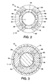
- FIG. 2 a cross-sectional view may be seen of the apparatus 10 representatively illustrated in FIG. 1A.
- the cross-section is taken through line 2-2 of FIG. 1A which extends laterally through the crossover 24.
- the manner in which circulation flow passage 38 extends longitudinally through the crossover 24 may be seen.
- Eight longitudinally extending and circumferentially spaced circulation ports 76 are disposed radially intermediate inner diameter 78 of the crossover 24 and outer diameter 80 of the crossover. Two each of the circulation ports 76 are disposed in the crossover 24 circumferentially intermediate each pair of exit ports 64.
- Flow ports 74 in protective sleeve 68 being somewhat smaller in width than the exit ports 64, act to protect the exit ports 64 from abrasion wear due to radially outwardly directed flow of the slurry. It may be clearly seen in FIG.
- exit ports 64 wear appreciably circumferentially outward, or if the protective sleeve 68 and inner diameter 78 of the crossover 24 wear appreciably radially outward, the exit ports 64 and flow passage 22 will eventually be in fluid communication with the circulation ports 76. If such abrasive wear of the crossover 24 does occur, the proppant slurry will be permitted to enter the circulation ports 76.
- FIG. 3 a cross-sectional view of the apparatus 10, taken laterally along line 3-3 of FIG. 1A may be seen.
- FIG. 3 further illustrates the manner in which the circulation ports 76 extend longitudinally through the crossover 24. It may thus be clearly seen that circulation ports 76 provide fluid communication for the circulation flow passage 38 from the upper connector 14 to the lower portion 30 of the crossover 24. Consequently, if the proppant slurry enters the circulation ports 76 adjacent the crossover exit ports 64 as above described, the proppant slurry will be permitted to enter the circulation flow passage 38 in the extension subs 48 and lower connector 16.
- the circulation flow passage 38 in the lower connector 16 is in fluid communication with various equipment (not shown) installed in the wellbore 12 below the apparatus 10.
- this equipment may include equipment known to those skilled in the art as washpipes and sand control screens. It is critical in such jobs that the washpipes and sand control screens not be filled with proppant, else they will have to be removed from the well, cleaned, and replaced at great expense.
- apparatus 10 includes specially designed features which prevent passage of the proppant into the circulation flow passage 38 in the lower connector 16, while still permitting circulation flow from the lower connector 16 to the upper connector 14 as normal.
- a coupling 82 is threadedly and sealingly attached to the plug 28 at a lower portion 84 of the plug.
- Coupling 82 is also threadedly and sealingly attached to a longitudinally extending perforated pipe 86 which is coaxially disposed within extension subs 48.
- the perforated pipe 86 is contained within two extension subs 48, but it is to be understood that a different number of extension subs 48 may be utilized and the perforated pipe 86 may be longer or shorter without departing from the principles of the present invention.
- extension subs 48 having a combined overall length of approximately eight to twelve feet and perforated pipe 86 having an overall length of approximately six to ten feet.
- Perforated pipe 86 may be extended by threadedly attaching another coupling 82 to a lower end 88 of the perforated pipe 86 and attaching another perforated pipe to the additional coupling 82.
- FIGS. 1A and 1B only one perforated pipe 86 is shown in FIGS. 1A and 1B.
- Perforated pipe 86 includes a series of longitudinally spaced apart openings 90 extending radially therethrough. Openings 90 permit fluid communication between the circulation flow passage 38 in an annular area 92 formed between the perforated pipe 86 and extension subs 48, and the circulation flow passage 38 within the lower connector 16. Although openings 90 are representatively illustrated in FIG. 1B as being circular and longitudinally aligned, it is to be understood that openings 90 may also have other shapes, for example, slotted, and may be longitudinally and circumferentially staggered or otherwise positioned on the perforated pipe 86 without departing from the principles of the present invention.
- the circulation flow passage 38 in the annular area 92 between the perforated pipe 86 and the extension subs 48 is separated from the circulation flow passage 38 in the lower connector 16 by an annular ring 94 threadedly and sealingly installed onto the lower end 88 of the perforated pipe 86 and coaxially disposed within the lower extension sub 48.
- a seal 96 sealingly engages the annular ring 94 and the lower extension sub 48.
- the screen 98 Radially outwardly overlying the perforated pipe 86 is a generally tubular screen 98.
- the screen 98 has openings therethrough which do not permit proppant to pass through the screen. Applicants prefer that the screen 98 have openings of approximately .006 - .008 inch, although other screen openings may be utilized without departing from the principles of the present invention.
- the screen 98 may be made of materials such as wrapped wire, sintered metal, or any other material suitable for screening proppant from the proppant slurry. Additionally, the screen 98 may be integrally formed with the perforated pipe 86, for example, the openings 90 may be very narrow slots. Applicants prefer a tubular welded sand screen for screen 98.
- Screen 98 is representatively illustrated in FIG. 1B as being welded at each of its opposite ends to the perforated pipe 86, longitudinally and radially outwardly overlying the openings 90 in the perforated pipe.
- any flow in the circulation flow passage 38 which passes from the annular area 92 to the lower connector 16 through the openings 90 must first pass through the screen 98.
- methods of sealingly attaching the screen 98 to the perforated pipe 86 other than welding may be utilized without departing from the principles of the present invention.
- Downwardly directed flow in the circulation flow passage 38 which has passed through the screen 98 and perforated pipe 86, next enters lower portion 100 of the lower extension sub 48.
- a ball 102 is contained within the lower portion 100 of the extension sub 48 between the annular ring 94 and a radially inwardly tapered surface 104 formed internally within the lower connector 16. Downwardly directed flow in the circulation flow passage 38 tends to bias the ball 102 against the surface 104. When biased against the surface 104, the ball 102 is sealingly engaged by the surface 104, except where circumferentially spaced and radially inclined grooves 106 have been formed in the lower connector 16.
- Grooves 106 permit a small amount of flow in the circulation flow passage 38 downwardly past the ball 102 to the lower portion 20 of the lower connector 16.
- Upwardly directed flow in the circulation flow passage 38 i.e., the "normal" flow direction in the circulation flow passage when there is no fluid communication between the proppant slurry in the exit ports 64 and the circulation flow ports 76 in the crossover 24 as described above
- the proppant containment apparatus 10 which permits a fracturing job to continue even after the crossover 24 has been abraded such that the proppant slurry enters the circulation flow ports 76.
- Use of the above described apparatus 10 prevents proppant from filling equipment below the crossover 24, such as wash pipe and sand control screens, and helps to prevent sticking of the service tool and wash pipe in the well. Failure of the crossover 24 will, using the apparatus 10, result in filling the annular area 92 with proppant, but the job will be capable of being continued.
- An additional benefit obtained from use of the proppant containment apparatus 10 is filtering of the normally upwardly directed flow in the circulation flow passage 38.
- upwardly directed flow in the circulation flow passage 38 usually does not contain any proppant, it usually is only the fluid portion of the proppant slurry. If however, proppant or foreign matter does enter the upwardly directed flow in circulation flow passage 38, it will not be able to pass through the screen 98.
- Screening proppant or foreign matter from upwardly directed flow in the circulation flow passage 38 aids in reducing wear of the seals 60 by preventing proppant from flowing between the service tool and the packer and being deposited between the service tool and the casing above the packer. Combined with other benefits, this helps permit the apparatus 10 to do more than one fracturing job without replacing the seals 60.
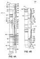
- FIGS. 4A and 4B Illustrated in FIGS. 4A and 4B is another embodiment 10a of the proppant containment apparatus 10.
- elements of the apparatus 10a representatively illustrated in FIGS. 4A and 4B which are substantially similar to those elements illustrated in the foregoing described figures are identified with the same item numbers as previously used.
- plug 28 does not have a coupling 82 attached to its lower end 84, or a perforated pipe 86 and screen 98 disposed in the extension sub 48.
- the embodiment of the apparatus 10a shown in FIGS. 4A and 4B differs in one respect from the embodiment 10 shown in FIGS. 1A and 1B in the method utilized to screen the proppant from downwardly directed flow in the circulation flow passage 38.
- an extension sub 108 has a longitudinally extended inner diameter 110 formed therein.
- the inner diameter 110 defines an internal annular pocket 112 between extension sub 48 and extension sub 108.
- a flat circular screen 114 is laterally disposed in the annular pocket 112.
- the flat circular screen 114 may be made of sintered metal or any other material capable of screening the proppant. Applicants prefer sintered metal for the flat screen 114 material because of its ability to withstand relatively high flow rates (approximately 1 - 5 barrels per minute) without breaking down or collapsing. Note that the portion of the flat screen 114 which extends laterally across the flow passage 38 is supported only at its edges in the annular pocket 112. Thickness of the flat screen 114 is preferably approximately 1 inch for a preferred diameter of approximately 2.25 inches. Larger diameter flat screens 114 or higher flow rates will typically require greater thicknesses or supporting gussets, etc. for sufficient rigidity. It is to be understood that various shapes and dimensions of the screen 114 may be utilized without departing from the principles of the present invention.
- Extension sub 108 is threadingly attached to extension sub 48 by tightening upper end 116 of extension sub 108 onto lower end 118 of extension sub 48.
- Screen 114 is partially compressed in the annular pocket 112 before upper end 116 contacts the seal ring 60 disposed between the extension subs 48 and 108. In this manner, screen 114 is sealingly engaged at its outer edge in the annular pocket 112 between lower end 118 and upper end 116 when extension sub 108 is attached to extension sub 48.
Landscapes
- Geology (AREA)
- Life Sciences & Earth Sciences (AREA)
- Engineering & Computer Science (AREA)
- Mining & Mineral Resources (AREA)
- Environmental & Geological Engineering (AREA)
- Fluid Mechanics (AREA)
- Physics & Mathematics (AREA)
- General Life Sciences & Earth Sciences (AREA)
- Geochemistry & Mineralogy (AREA)
- Filtration Of Liquid (AREA)
- Structure Of Emergency Protection For Nuclear Reactors (AREA)
- Consolidation Of Soil By Introduction Of Solidifying Substances Into Soil (AREA)
- On-Site Construction Work That Accompanies The Preparation And Application Of Concrete (AREA)
Priority Applications (1)
| Application Number | Priority Date | Filing Date | Title |
|---|---|---|---|
| EP02075750A EP1221534A3 (fr) | 1996-01-16 | 1997-01-16 | Dispositif pour contenir un agent de soutènement et procédés pour son utilisation |
Applications Claiming Priority (2)
| Application Number | Priority Date | Filing Date | Title |
|---|---|---|---|
| US587352 | 1996-01-16 | ||
| US08/587,352 US5787985A (en) | 1996-01-16 | 1996-01-16 | Proppant containment apparatus and methods of using same |
Related Child Applications (1)
| Application Number | Title | Priority Date | Filing Date |
|---|---|---|---|
| EP02075750A Division EP1221534A3 (fr) | 1996-01-16 | 1997-01-16 | Dispositif pour contenir un agent de soutènement et procédés pour son utilisation |
Publications (2)
| Publication Number | Publication Date |
|---|---|
| EP0785337A2 true EP0785337A2 (fr) | 1997-07-23 |
| EP0785337A3 EP0785337A3 (fr) | 1998-07-08 |
Family
ID=24349454
Family Applications (2)
| Application Number | Title | Priority Date | Filing Date |
|---|---|---|---|
| EP97300253A Withdrawn EP0785337A3 (fr) | 1996-01-16 | 1997-01-16 | Dispositif pour contenir un agent de soutènement et procédés pour son utilisation |
| EP02075750A Withdrawn EP1221534A3 (fr) | 1996-01-16 | 1997-01-16 | Dispositif pour contenir un agent de soutènement et procédés pour son utilisation |
Family Applications After (1)
| Application Number | Title | Priority Date | Filing Date |
|---|---|---|---|
| EP02075750A Withdrawn EP1221534A3 (fr) | 1996-01-16 | 1997-01-16 | Dispositif pour contenir un agent de soutènement et procédés pour son utilisation |
Country Status (2)
| Country | Link |
|---|---|
| US (2) | US5787985A (fr) |
| EP (2) | EP0785337A3 (fr) |
Cited By (2)
| Publication number | Priority date | Publication date | Assignee | Title |
|---|---|---|---|---|
| GB2322887A (en) * | 1997-01-31 | 1998-09-09 | Halliburton Energy Serv Inc | Proppant slurry screen apparatus |
| US6367548B1 (en) | 1999-03-05 | 2002-04-09 | Bj Services Company | Diversion treatment method |
Families Citing this family (44)
| Publication number | Priority date | Publication date | Assignee | Title |
|---|---|---|---|---|
| US6125937A (en) * | 1997-02-13 | 2000-10-03 | Halliburton Energy Services, Inc. | Methods of completing a subterranean well and associated apparatus |
| US6491097B1 (en) * | 2000-12-14 | 2002-12-10 | Halliburton Energy Services, Inc. | Abrasive slurry delivery apparatus and methods of using same |
| US6598685B1 (en) * | 2002-02-14 | 2003-07-29 | Benny Donald Mashburn | Drilling fluid screen and method |
| US7243740B2 (en) * | 2003-12-05 | 2007-07-17 | Pathfinder Energy Services, Inc. | Filter assembly having a bypass passageway and method |
| US20060052251A1 (en) * | 2004-09-09 | 2006-03-09 | Anderson David K | Time release multisource marker and method of deployment |
| US7213641B2 (en) * | 2004-11-02 | 2007-05-08 | Stinger Wellhead Protection, Inc. | Fracturing head with replaceable inserts for improved wear resistance and method of refurbishing same |
| US7387165B2 (en) * | 2004-12-14 | 2008-06-17 | Schlumberger Technology Corporation | System for completing multiple well intervals |
| US7322417B2 (en) * | 2004-12-14 | 2008-01-29 | Schlumberger Technology Corporation | Technique and apparatus for completing multiple zones |
| GB2435656B (en) * | 2005-03-15 | 2009-06-03 | Schlumberger Holdings | Technique and apparatus for use in wells |
| US20060213667A1 (en) * | 2005-03-28 | 2006-09-28 | Mashburn Benny D | Screen apparatus and method |
| US8371369B2 (en) * | 2007-12-04 | 2013-02-12 | Baker Hughes Incorporated | Crossover sub with erosion resistant inserts |
| US7762324B2 (en) * | 2007-12-04 | 2010-07-27 | Baker Hughes Incorporated | Bypass crossover sub selector for multi-zone fracturing processes |
| US7624810B2 (en) * | 2007-12-21 | 2009-12-01 | Schlumberger Technology Corporation | Ball dropping assembly and technique for use in a well |
| US7789133B2 (en) * | 2008-03-20 | 2010-09-07 | Stinger Wellhead Protection, Inc. | Erosion resistant frac head |
| US8820400B2 (en) | 2008-03-20 | 2014-09-02 | Oil States Energy Services, L.L.C. | Erosion resistant frac head |
| US8028768B2 (en) * | 2009-03-17 | 2011-10-04 | Schlumberger Technology Corporation | Displaceable plug in a tool string filter |
| US20110132613A1 (en) * | 2009-12-09 | 2011-06-09 | Baker Hughes Incorporated | Multiple Port Crossover Tool with Port Selection Feature |
| CA2799940C (fr) | 2010-05-21 | 2015-06-30 | Schlumberger Canada Limited | Procede et appareil pour deployer et utiliser des dispositifs de fond de trou a positionnement automatique |
| US8297358B2 (en) | 2010-07-16 | 2012-10-30 | Baker Hughes Incorporated | Auto-production frac tool |
| US8347969B2 (en) | 2010-10-19 | 2013-01-08 | Baker Hughes Incorporated | Apparatus and method for compensating for pressure changes within an isolated annular space of a wellbore |
| US9382790B2 (en) | 2010-12-29 | 2016-07-05 | Schlumberger Technology Corporation | Method and apparatus for completing a multi-stage well |
| US8752631B2 (en) | 2011-04-07 | 2014-06-17 | Baker Hughes Incorporated | Annular circulation valve and methods of using same |
| US8869898B2 (en) | 2011-05-17 | 2014-10-28 | Baker Hughes Incorporated | System and method for pinpoint fracturing initiation using acids in open hole wellbores |
| US8944171B2 (en) | 2011-06-29 | 2015-02-03 | Schlumberger Technology Corporation | Method and apparatus for completing a multi-stage well |
| US8739889B2 (en) | 2011-08-01 | 2014-06-03 | Baker Hughes Incorporated | Annular pressure regulating diaphragm and methods of using same |
| US10364629B2 (en) | 2011-09-13 | 2019-07-30 | Schlumberger Technology Corporation | Downhole component having dissolvable components |
| US9033041B2 (en) | 2011-09-13 | 2015-05-19 | Schlumberger Technology Corporation | Completing a multi-stage well |
| US9752407B2 (en) | 2011-09-13 | 2017-09-05 | Schlumberger Technology Corporation | Expandable downhole seat assembly |
| US9534471B2 (en) | 2011-09-30 | 2017-01-03 | Schlumberger Technology Corporation | Multizone treatment system |
| US9394752B2 (en) | 2011-11-08 | 2016-07-19 | Schlumberger Technology Corporation | Completion method for stimulation of multiple intervals |
| US9238953B2 (en) | 2011-11-08 | 2016-01-19 | Schlumberger Technology Corporation | Completion method for stimulation of multiple intervals |
| US9279306B2 (en) | 2012-01-11 | 2016-03-08 | Schlumberger Technology Corporation | Performing multi-stage well operations |
| US8844637B2 (en) | 2012-01-11 | 2014-09-30 | Schlumberger Technology Corporation | Treatment system for multiple zones |
| US9650851B2 (en) | 2012-06-18 | 2017-05-16 | Schlumberger Technology Corporation | Autonomous untethered well object |
| US9988867B2 (en) | 2013-02-01 | 2018-06-05 | Schlumberger Technology Corporation | Deploying an expandable downhole seat assembly |
| WO2015012821A1 (fr) * | 2013-07-24 | 2015-01-29 | Halliburton Energy Services, Inc. | Procédés et systèmes de filtrage de production |
| US9631468B2 (en) | 2013-09-03 | 2017-04-25 | Schlumberger Technology Corporation | Well treatment |
| US9587477B2 (en) | 2013-09-03 | 2017-03-07 | Schlumberger Technology Corporation | Well treatment with untethered and/or autonomous device |
| US10487625B2 (en) | 2013-09-18 | 2019-11-26 | Schlumberger Technology Corporation | Segmented ring assembly |
| US9644452B2 (en) | 2013-10-10 | 2017-05-09 | Schlumberger Technology Corporation | Segmented seat assembly |
| CN104819915B (zh) * | 2015-01-14 | 2018-07-13 | 中国石油天然气股份有限公司 | 一种压裂支撑剂圆度、球度测试方法 |
| US10538988B2 (en) | 2016-05-31 | 2020-01-21 | Schlumberger Technology Corporation | Expandable downhole seat assembly |
| CN106153507B (zh) * | 2016-06-20 | 2018-10-02 | 青岛石大石仪科技有限责任公司 | 一种测试压裂支撑剂圆球度的方法 |
| US11732562B1 (en) | 2021-04-27 | 2023-08-22 | Gulfstream Services, Inc. | Offshore frac head clamp apparatus and method of use thereof |
Family Cites Families (23)
| Publication number | Priority date | Publication date | Assignee | Title |
|---|---|---|---|---|
| US14756A (en) * | 1856-04-22 | Studs fob wearing-apparel | ||
| US565890A (en) * | 1896-08-18 | Filter | ||
| US1447234A (en) * | 1920-10-14 | 1923-03-06 | Monroe W Carroll | Rotary drill bit |
| US2646752A (en) * | 1949-11-25 | 1953-07-28 | Dresser Equipment Company | Pump with inlet strainer |
| US2843054A (en) * | 1954-01-07 | 1958-07-15 | Shell Dev | Tubing string sand trap |
| US3314481A (en) * | 1964-08-07 | 1967-04-18 | Exxon Production Research Co | Downhole water filter |
| US3425490A (en) * | 1968-04-26 | 1969-02-04 | Glen G Clayton | Cleaning assembly |
| US3515210A (en) * | 1968-06-20 | 1970-06-02 | Halliburton Co | Filter apparatus for well tool string |
| US4083660A (en) * | 1975-08-04 | 1978-04-11 | Newbrough Joseph S | Gas drive oil well pumping system having mixing means for the gas/oil mixture |
| US4055498A (en) * | 1975-08-06 | 1977-10-25 | Desmond Arpad Radnoti | Selective filtration apparatus |
| US4286659A (en) * | 1979-08-28 | 1981-09-01 | Aztec Tools, Inc. | Ball valve safety screen |
| US4495073A (en) * | 1983-10-21 | 1985-01-22 | Baker Oil Tools, Inc. | Retrievable screen device for drill pipe and the like |
| US4627488A (en) * | 1985-02-20 | 1986-12-09 | Halliburton Company | Isolation gravel packer |
| US4840229A (en) * | 1986-03-31 | 1989-06-20 | Otis Engineering Corporation | Multiple position service seal unit with positive position indicating means |
| US4722392A (en) * | 1986-03-31 | 1988-02-02 | Otis Engineering Corporation | Multiple position service seal unit with positive position indicating means |
| US4921044A (en) * | 1987-03-09 | 1990-05-01 | Otis Engineering Corporation | Well injection systems |
| US5062484A (en) * | 1990-08-24 | 1991-11-05 | Marathon Oil Company | Method of gravel packing a subterranean well |
| US5090478A (en) * | 1990-11-30 | 1992-02-25 | Conoco Inc. | Method for reducing water production from a gravel packed well |
| US5335727A (en) * | 1992-11-04 | 1994-08-09 | Atlantic Richfield Company | Fluid loss control system for gravel pack assembly |
| US5330003A (en) * | 1992-12-22 | 1994-07-19 | Bullick Robert L | Gravel packing system with diversion of fluid |
| US5494107A (en) * | 1993-12-07 | 1996-02-27 | Bode; Robert E. | Reverse cementing system and method |
| US5443117A (en) * | 1994-02-07 | 1995-08-22 | Halliburton Company | Frac pack flow sub |
| US5515915A (en) * | 1995-04-10 | 1996-05-14 | Mobil Oil Corporation | Well screen having internal shunt tubes |
-
1996
- 1996-01-16 US US08/587,352 patent/US5787985A/en not_active Expired - Fee Related
-
1997
- 1997-01-16 EP EP97300253A patent/EP0785337A3/fr not_active Withdrawn
- 1997-01-16 EP EP02075750A patent/EP1221534A3/fr not_active Withdrawn
-
1998
- 1998-01-28 US US09/014,982 patent/US6155342A/en not_active Expired - Fee Related
Non-Patent Citations (1)
| Title |
|---|
| None |
Cited By (5)
| Publication number | Priority date | Publication date | Assignee | Title |
|---|---|---|---|---|
| GB2322887A (en) * | 1997-01-31 | 1998-09-09 | Halliburton Energy Serv Inc | Proppant slurry screen apparatus |
| US5924487A (en) * | 1997-01-31 | 1999-07-20 | Halliburton Energy Services, Inc. | Proppant slurry screen apparatus and methods of using same |
| US5988271A (en) * | 1997-01-31 | 1999-11-23 | Halliburton Energy Services, Inc. | Proppant slurry screen apparatus and methods of using same |
| GB2322887B (en) * | 1997-01-31 | 2001-05-30 | Halliburton Energy Serv Inc | Proppant slurry screen apparatus |
| US6367548B1 (en) | 1999-03-05 | 2002-04-09 | Bj Services Company | Diversion treatment method |
Also Published As
| Publication number | Publication date |
|---|---|
| US5787985A (en) | 1998-08-04 |
| US6155342A (en) | 2000-12-05 |
| EP1221534A2 (fr) | 2002-07-10 |
| EP0785337A3 (fr) | 1998-07-08 |
| EP1221534A3 (fr) | 2004-02-04 |
Similar Documents
| Publication | Publication Date | Title |
|---|---|---|
| US5787985A (en) | Proppant containment apparatus and methods of using same | |
| US6857476B2 (en) | Sand control screen assembly having an internal seal element and treatment method using the same | |
| US5676208A (en) | Apparatus and methods of preventing screen collapse in gravel packing operations | |
| US7096945B2 (en) | Sand control screen assembly and treatment method using the same | |
| US6601646B2 (en) | Apparatus and method for sequentially packing an interval of a wellbore | |
| EP0789131B1 (fr) | Appareil de puits pour la délivrance d'un liquide abrasif | |
| US6491097B1 (en) | Abrasive slurry delivery apparatus and methods of using same | |
| US6886634B2 (en) | Sand control screen assembly having an internal isolation member and treatment method using the same | |
| US6719051B2 (en) | Sand control screen assembly and treatment method using the same | |
| US6675891B2 (en) | Apparatus and method for gravel packing a horizontal open hole production interval | |
| US6176307B1 (en) | Tubing-conveyed gravel packing tool and method | |
| CA2364917C (fr) | Dispositif et methode fournissant un trajet auxiliaire au debit d'un fluide servant a la completion du gravillonnage des crepines | |
| US20030141061A1 (en) | Sand control screen assembly and treatment method using the same | |
| US10428635B2 (en) | System and method for removing sand from a wellbore | |
| US20030000699A1 (en) | Apparatus and method for gravel packing an interval of a wellbore | |
| US20020104655A1 (en) | Apparatus and methods for gravel pack completions | |
| MXPA02004983A (es) | Metodo para controlar el reflujo de consolidacion en un pozo. | |
| US6715545B2 (en) | Transition member for maintaining for fluid slurry velocity therethrough and method for use of same | |
| US20070062686A1 (en) | Flow nozzle assembly | |
| US7114558B2 (en) | Filtered actuator port for hydraulically actuated downhole tools | |
| US20060191685A1 (en) | Multiple port cross-over design for frac-pack erosion mitigation | |
| US5924487A (en) | Proppant slurry screen apparatus and methods of using same | |
| EP0935050A2 (fr) | Coude de croisement résistant à l'usure | |
| US11466520B2 (en) | Systems and methods for indicating completion of a reverse cementing operation | |
| US20060037752A1 (en) | Rat hole bypass for gravel packing assembly |
Legal Events
| Date | Code | Title | Description |
|---|---|---|---|
| PUAI | Public reference made under article 153(3) epc to a published international application that has entered the european phase |
Free format text: ORIGINAL CODE: 0009012 |
|
| AK | Designated contracting states |
Kind code of ref document: A2 Designated state(s): DE FR GB NL |
|
| PUAL | Search report despatched |
Free format text: ORIGINAL CODE: 0009013 |
|
| AK | Designated contracting states |
Kind code of ref document: A3 Designated state(s): DE FR GB NL |
|
| RHK1 | Main classification (correction) |
Ipc: E21B 43/26 |
|
| 17P | Request for examination filed |
Effective date: 19990108 |
|
| 17Q | First examination report despatched |
Effective date: 20001006 |
|
| GRAH | Despatch of communication of intention to grant a patent |
Free format text: ORIGINAL CODE: EPIDOS IGRA |
|
| GRAH | Despatch of communication of intention to grant a patent |
Free format text: ORIGINAL CODE: EPIDOS IGRA |
|
| STAA | Information on the status of an ep patent application or granted ep patent |
Free format text: STATUS: THE APPLICATION IS DEEMED TO BE WITHDRAWN |
|
| 18D | Application deemed to be withdrawn |
Effective date: 20030801 |