EP0785142A1 - Crate moulded in plastic having inward folding sides - Google Patents
Crate moulded in plastic having inward folding sides Download PDFInfo
- Publication number
- EP0785142A1 EP0785142A1 EP97830007A EP97830007A EP0785142A1 EP 0785142 A1 EP0785142 A1 EP 0785142A1 EP 97830007 A EP97830007 A EP 97830007A EP 97830007 A EP97830007 A EP 97830007A EP 0785142 A1 EP0785142 A1 EP 0785142A1
- Authority
- EP
- European Patent Office
- Prior art keywords
- sides
- crate
- transverse
- longitudinal
- groove
- Prior art date
- Legal status (The legal status is an assumption and is not a legal conclusion. Google has not performed a legal analysis and makes no representation as to the accuracy of the status listed.)
- Withdrawn
Links
Images

Classifications
-
- B—PERFORMING OPERATIONS; TRANSPORTING
- B65—CONVEYING; PACKING; STORING; HANDLING THIN OR FILAMENTARY MATERIAL
- B65D—CONTAINERS FOR STORAGE OR TRANSPORT OF ARTICLES OR MATERIALS, e.g. BAGS, BARRELS, BOTTLES, BOXES, CANS, CARTONS, CRATES, DRUMS, JARS, TANKS, HOPPERS, FORWARDING CONTAINERS; ACCESSORIES, CLOSURES, OR FITTINGS THEREFOR; PACKAGING ELEMENTS; PACKAGES
- B65D11/00—Containers having bodies formed by interconnecting or uniting two or more rigid, or substantially rigid, components made wholly or mainly of plastics material
- B65D11/18—Containers having bodies formed by interconnecting or uniting two or more rigid, or substantially rigid, components made wholly or mainly of plastics material collapsible, i.e. with walls hinged together or detachably connected
- B65D11/1833—Containers having bodies formed by interconnecting or uniting two or more rigid, or substantially rigid, components made wholly or mainly of plastics material collapsible, i.e. with walls hinged together or detachably connected whereby all side walls are hingedly connected to the base panel
Definitions
- This patent application for a utility model concerns a crate moulded in plastic with inward folding sides.
- Moulded plastic crates are currently widely used thanks to the fact that they are light, sturdy and inexpensive.
- This type of crate has four lateral sides which, during use, are locked reciprocally in a vertical position; when the crates are not used, the coupling of the sides is released in order to fold the same downwards and inwards.
- These sides are hinged for this purpose to the four sides of the bottom of the crate, with respect to which they can be folded from a vertical position, when in use, to a horizontal position, when they are not used and vice versa.
- folding of the sides must be performed in a specific order; to go from a horizontal to a vertical position it is necessary to open the longitudinal sides and then the transverse sides, and vice versa from a vertical to a horizontal position.
- the transverse edges of the long sides are provided with two or more hooked teeth designed to house and wedge into corresponding hollowed housings - at a suitable height - on the transverse edges of the short sides.
- hooking means makes the reciprocal locking and unlocking of the sides so difficult since in order to lock the four sides of a crate of this kind, it is necessary to move first the longitudinal and then the transverse sides to a vertical position, align the teeth of the longitudinal sides and the housings of the transverse sides precisely, and finally press to ensure that said hooking means of the four sides wedge into place.
- the main problem when locking the sides is the difficulty in aligning the teeth of the longitudinal sides and the corresponding housings on the transverse sides quickly enough.
- the item according to the invention is designed to eliminate the problems encountered with conventional crates when locking and releasing the sides.
- the inventive idea provides the crates in question with a different locking mechanism of the sides, which does not require the user to personally align and couple the means which permit the stable fixing of the four crate sides.
- said fixing means are permanently coupled, so that all the user is required to do when opening and closing the crate, is to fold the sides over.
- the new crate in question consists generally of four folding sides hinged to the four edges of the bottom wall; here, as in the case of conventional crates, the four walls may be moved from a vertical position, inwards, to abut against the bottom wall, and vice versa from a horizontal position when the crate is not used to a vertical position when the crate is used.
- each of the transverse edges of the short sides are provided with two projecting pins with enlarged head, made of the same material and during the same moulding phase as the transverse sides.
- Another consequent feature of the crate according to the invention is that the internal surface of each longitudinal side is provided with two pairs of concentric curved grooves whose centre coincides with the pivoting axis of the transverse side; in other words, said grooves correspond to the same number of hooking and sliding runners for the pins made on the transverse sides.
- each of these pairs is located at one of the ends of said longitudinal side.
- Each groove is curved for a quarter of the circumference, starting from the hinged edge of the longitudinal wall and ending at the transverse side of the same side.
- Said longitudinal sides are pivoted, on the bottom, to a raised edge which is an integral part of the bottom of the crate, and is characterised by a height equal to the thickness of the transverse sides, which, when turned flat against the bottom of the crate, wedge precisely into the raised edges to which the long sides are pivoted.
- each of said edges are provided with four perfectly aligned notches with the mouth of the four curved grooves made on the internal surface of each longitudinal wall.
- the crate In order to describe the method of locking the sides of the new crate in question, the crate is considered to be in a "compacted" position.
- the first step is to fold the two longitudinal opposing sides from a horizontal to a vertical position.
- the first effect of folding the transverse walls upwards is to immediately wedge the two pairs of pins projecting from the two sides of each of said transverse sides, into the mouth of the two pairs of grooves, which, as mentioned above, are perfectly aligned with the notches on the raised hinging edges of the longitudinal sides.
- Said grooves are designed to house and guide the pins during folding of the corresponding transverse sides.
- each runner is provided with a pair of jaws which wedge the leg of a pin, whose enlarged head remains outside the pair of jaws, turned towards the exterior of the crate.
- the full length of the sliding runners of the pins is provided with two rims between which the leg of the pin slides, while the relevant enlarged head of the pin remains wedged outside the pair of rims.
- Releasing the sides of the crate according to the invention is achieved simply by uncoupling the pins of the transverse sides from the jaws at the upper end of the corresponding runner.
- the crate (1)-entirely moulded in plastic - consists of a bottom wall (2) and two opposing pairs of folding lateral sides (3 and 4).
- Said walls are hinged to the bottom (2) of crate (1); in particular, the two longitudinal sides (3) are hinged to corresponding raised edges (2a) on the long sides of the bottom (2) of the crate (1) and characterised by a height (H) equal to the thickness (S) of the transverse sides (4).
- Said transverse sides (4) are in turn hinged directly on the short sides of the bottom (2) of the crate (1).
- Each of the four sides (3 and 4) is in fact provided on its bottom side with a series of notches (5) having corresponding pivoting pins (6) designed to wedge into corresponding specific jaws along the four sides of the bottom (2) of the crate (1).
- Each of the transverse sides (4) of the crate in question (1) is characterised by two pins (7) with enlarged head (7a) for each of its lateral edges while each longitudinal side (3) is characterised in that its internal surface is provided with two pairs of concentric curved runners (8) corresponding to a quarter of the circumference and whose centre coincides with the pivoting axis of the sides (4).
- each groove (8) positioned on the bottom side of its corresponding logitudinal side (3) overlies and is aligned perfectly to a notch (9) on the raised edge (2a) on which the longitudinal side is hinged.
- each of said grooves (8) which is positioned on the side edge of the corresponding side (3), is provided with a pair of jaws (10) designed to wedge and fix the leg of pin (7) housed and sliding in the groove (8).
- said pair of jaws (10) correspond to the shaped end section of an opposing pair of rims (10a) whose purpose is to reduce the space of the groove (8) so that it is equal to the diameter of the leg of pin (7), whose enlarged head (7a) has a diameter equal to the width of the groove (8) and remains wedged out of said pair of rims (10a), facing towards the exterior of the crate (1).
- this feature permits on one hand the guided sliding of the pins (7) of the transverse sides (4) in the corresponding grooves (8) of the longitudinal sides (3) and on the other hand it prevents the accidental removal of said pins (7) from the corresponding grooves (8) and thus the uncoupling of the longitudinal sides (3) from the transverse walls (4).
Landscapes
- Engineering & Computer Science (AREA)
- Mechanical Engineering (AREA)
- Rigid Containers With Two Or More Constituent Elements (AREA)
Abstract
This invention concerns a crate (1) moulded in plastic having inward folding sides (3,4) characterised in that the transverse sides (4) are provided with lateral pins coupled and sliding within corresponding runners (8) on the interior surface of the longitudinal sides (3); the cooperation of said pins and grooves making the reciprocal locking of the sides in vertical position and subsequent release very fast and easy.
Description
- This patent application for a utility model concerns a crate moulded in plastic with inward folding sides.
- Moulded plastic crates are currently widely used thanks to the fact that they are light, sturdy and inexpensive.
- In order to solve the problem of storage and transportation of these crates, they have been made for some time with inward folding sides which can therefore be turned from a vertical to a horizontal position until they are parallel and overlying with respect to the centre bottom wall.
- This type of crate has four lateral sides which, during use, are locked reciprocally in a vertical position; when the crates are not used, the coupling of the sides is released in order to fold the same downwards and inwards.
- These sides are hinged for this purpose to the four sides of the bottom of the crate, with respect to which they can be folded from a vertical position, when in use, to a horizontal position, when they are not used and vice versa.
- Generally, folding of the sides must be performed in a specific order; to go from a horizontal to a vertical position it is necessary to open the longitudinal sides and then the transverse sides, and vice versa from a vertical to a horizontal position.
- It is thus understandable that when the crate is not used its appearance is that of a three-layer "package": the first and bottom layer consisting of the actual bottom wall, the second and middle layer consisting of the two transverse sides and the third and overlying layer consisting of the two longitudinal sides.
- The problem in using the current models of this crate with folding sides is that it is difficult to lock and release the side walls.
- According to current technology, the transverse edges of the long sides are provided with two or more hooked teeth designed to house and wedge into corresponding hollowed housings - at a suitable height - on the transverse edges of the short sides.
- It is the use of these hooking means that makes the reciprocal locking and unlocking of the sides so difficult since in order to lock the four sides of a crate of this kind, it is necessary to move first the longitudinal and then the transverse sides to a vertical position, align the teeth of the longitudinal sides and the housings of the transverse sides precisely, and finally press to ensure that said hooking means of the four sides wedge into place.
- The main problem when locking the sides is the difficulty in aligning the teeth of the longitudinal sides and the corresponding housings on the transverse sides quickly enough.
- When releasing the sides, it is very difficult to separate the teeth on the longitudinal sides from the corresponding housings on the transverse sides since the teeth are held very firmly in the housings so that it is difficult to separate them from the same.
- Moreover, in order to separate the sides it is also necessary to slide the adjacent sides reciprocally in order to translate the teeth of each wall sufficiently to release the hooked ends from the corresponding locking housings.
- The item according to the invention is designed to eliminate the problems encountered with conventional crates when locking and releasing the sides.
- In order to solve these problems the inventive idea provides the crates in question with a different locking mechanism of the sides, which does not require the user to personally align and couple the means which permit the stable fixing of the four crate sides.
- In the case of the model according to the invention, said fixing means are permanently coupled, so that all the user is required to do when opening and closing the crate, is to fold the sides over.
- The new crate in question consists generally of four folding sides hinged to the four edges of the bottom wall; here, as in the case of conventional crates, the four walls may be moved from a vertical position, inwards, to abut against the bottom wall, and vice versa from a horizontal position when the crate is not used to a vertical position when the crate is used.
- The new crate is characterised in that each of the transverse edges of the short sides are provided with two projecting pins with enlarged head, made of the same material and during the same moulding phase as the transverse sides. Another consequent feature of the crate according to the invention is that the internal surface of each longitudinal side is provided with two pairs of concentric curved grooves whose centre coincides with the pivoting axis of the transverse side; in other words, said grooves correspond to the same number of hooking and sliding runners for the pins made on the transverse sides.
- Moreover, each of these pairs is located at one of the ends of said longitudinal side.
- Each groove is curved for a quarter of the circumference, starting from the hinged edge of the longitudinal wall and ending at the transverse side of the same side.
- Said longitudinal sides are pivoted, on the bottom, to a raised edge which is an integral part of the bottom of the crate, and is characterised by a height equal to the thickness of the transverse sides, which, when turned flat against the bottom of the crate, wedge precisely into the raised edges to which the long sides are pivoted.
- In this regard, it should be noted that each of said edges are provided with four perfectly aligned notches with the mouth of the four curved grooves made on the internal surface of each longitudinal wall.
- In order to describe the method of locking the sides of the new crate in question, the crate is considered to be in a "compacted" position.
- It should be noted that when the crate is in this position, the pins projecting from the sides of the transverse sides are housed in the notches on the raised hinging edges of the longitudinal sides.
- In general, the first step is to fold the two longitudinal opposing sides from a horizontal to a vertical position.
- It is then necessary to perform the same action with the two transverse sides.
- The first effect of folding the transverse walls upwards is to immediately wedge the two pairs of pins projecting from the two sides of each of said transverse sides, into the mouth of the two pairs of grooves, which, as mentioned above, are perfectly aligned with the notches on the raised hinging edges of the longitudinal sides.
- Said grooves are designed to house and guide the pins during folding of the corresponding transverse sides.
- Once each pin is wedged into the corresponding runner, the transverse sides can be folded into a perfectly vertical position.
- When the transverse sides are in vertical position, the pins in the curved runners are at the end of their stroke.
- In fact, the upper end of each runner is provided with a pair of jaws which wedge the leg of a pin, whose enlarged head remains outside the pair of jaws, turned towards the exterior of the crate.
- The interposition of said pair of jaws between the head of the pin and the edge of the transverse wall from which the pin projects is the feature which prevents the risk of accidental removal of the pin from the corresponding runner and consequent uncoupling of the transverse and longitudinal sides, once the same are all in a vertical position.
- Moreover, for the same purpose, the full length of the sliding runners of the pins is provided with two rims between which the leg of the pin slides, while the relevant enlarged head of the pin remains wedged outside the pair of rims.
- Releasing the sides of the crate according to the invention, is achieved simply by uncoupling the pins of the transverse sides from the jaws at the upper end of the corresponding runner.
- Even if the hold of said jaws is rather strong, releasing the pins from the same is achieved simply by pressing in the transverse sides firmly inwards with respect to the crate, namely towards a horizontal position.
- It is easy to understand that releasing the walls of the crate in question is much easier than in the case of the prior technology in that the operation is carried out without having to first slide the adjacent sides reciprocally.
- For major clarity, the description of the invention continues with reference to the enclosed drawings intended for purposes of illustration and not in a limiting sense, whereby:
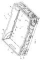
- figure 1 is an axonometric representation of the crate according to the invention;
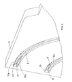
- figure 2 is an axonometric representation of an enlargement of one end of one of the longitudinal sides of the crate according to the invention;
- figure 3 is an axonometric representation of one of the transverse sides of the crate shown by an internal view.
- With reference to the enclosed drawings, the crate (1)-entirely moulded in plastic - consists of a bottom wall (2) and two opposing pairs of folding lateral sides (3 and 4).
- Said walls are hinged to the bottom (2) of crate (1); in particular, the two longitudinal sides (3) are hinged to corresponding raised edges (2a) on the long sides of the bottom (2) of the crate (1) and characterised by a height (H) equal to the thickness (S) of the transverse sides (4).
- Said transverse sides (4) are in turn hinged directly on the short sides of the bottom (2) of the crate (1). Each of the four sides (3 and 4) is in fact provided on its bottom side with a series of notches (5) having corresponding pivoting pins (6) designed to wedge into corresponding specific jaws along the four sides of the bottom (2) of the crate (1).
- Each of the transverse sides (4) of the crate in question (1) is characterised by two pins (7) with enlarged head (7a) for each of its lateral edges while each longitudinal side (3) is characterised in that its internal surface is provided with two pairs of concentric curved runners (8) corresponding to a quarter of the circumference and whose centre coincides with the pivoting axis of the sides (4).
- The bottom mouth of each groove (8), positioned on the bottom side of its corresponding logitudinal side (3) overlies and is aligned perfectly to a notch (9) on the raised edge (2a) on which the longitudinal side is hinged.
- With particular reference to figure 2, the upper end of each of said grooves (8), which is positioned on the side edge of the corresponding side (3), is provided with a pair of jaws (10) designed to wedge and fix the leg of pin (7) housed and sliding in the groove (8).
- More precisely, said pair of jaws (10) correspond to the shaped end section of an opposing pair of rims (10a) whose purpose is to reduce the space of the groove (8) so that it is equal to the diameter of the leg of pin (7), whose enlarged head (7a) has a diameter equal to the width of the groove (8) and remains wedged out of said pair of rims (10a), facing towards the exterior of the crate (1).
- As previously explained, this feature permits on one hand the guided sliding of the pins (7) of the transverse sides (4) in the corresponding grooves (8) of the longitudinal sides (3) and on the other hand it prevents the accidental removal of said pins (7) from the corresponding grooves (8) and thus the uncoupling of the longitudinal sides (3) from the transverse walls (4).
- It is also important to point out that more than two sliding and guiding grooves (8) for the pins (7) may be fitted at each end of the longitudinal walls (3), provided that the number of pins (7) on the transverse sides (4) is modified accordingly.
- Finally, it should be noted that in figure 1, the crate in question is provided with sides having external stiffening ribbing; this preferred embodiment is not however binding for the realisation of this invention.
Claims (1)
- A crate moulded in plastic having inward folding sides of the type consisting of a bottom wall (2) and two opposing pairs of folding side walls (3 and 4), the transverse sides (4) of which are hinged to a pair of opposing edges on the bottom (1), while the longitudinal sides (3) are hinged to corresponding raised edges (2a) on the long sides of the bottom (2) of the crate (1), and having a height (H) equal to thickness (S) of the transverse sides (4) characterised in that each of its two transverse sides (4) is provided, for each of its side edges, with one or more pins (7) having an enlarged head (7a) designed to couple with corresponding hooking and sliding runners (8) made at the ends of the internal surface of the longitudinal sides (3) being curved for a quarter of the circumference with the centre coinciding with the pivoting axis of the sides (4); the bottom mouth of each groove (8), positioned on the bottom side of the corresponding longitudinal side (3), being overlying and aligned perfectly to a notch (9) made on the raised edge (2a) on which the side (3) is hinged; each groove (8) being provided internally with two rims (10a) having a space between the same equal to the thickness of the pin (7) leg; said rim (10a) being shaped - at the upper end of each groove (8) - to form a pair of jaws (10) designed to hook and fasten the leg of the pin (7) sliding in the groove (8).
Applications Claiming Priority (2)
| Application Number | Priority Date | Filing Date | Title |
|---|---|---|---|
| ITAN960002 IT242479Y1 (en) | 1996-01-18 | 1996-01-18 | PRINTED BOX IN PLASTIC MATERIALS EQUIPPED WITH FOLDING SIDES INSIDE THE INSIDE |
| ITAN960002U | 1996-01-18 |
Publications (1)
| Publication Number | Publication Date |
|---|---|
| EP0785142A1 true EP0785142A1 (en) | 1997-07-23 |
Family
ID=11333948
Family Applications (1)
| Application Number | Title | Priority Date | Filing Date |
|---|---|---|---|
| EP97830007A Withdrawn EP0785142A1 (en) | 1996-01-18 | 1997-01-15 | Crate moulded in plastic having inward folding sides |
Country Status (2)
| Country | Link |
|---|---|
| EP (1) | EP0785142A1 (en) |
| IT (1) | IT242479Y1 (en) |
Cited By (34)
| Publication number | Priority date | Publication date | Assignee | Title |
|---|---|---|---|---|
| EP0962396A1 (en) * | 1998-06-05 | 1999-12-08 | Sergio Tontarelli | Plastic moulded crate provided with folding sides |
| EP1225131A1 (en) * | 2001-01-17 | 2002-07-24 | Sanko Co., Ltd. | Folding container |
| US6863180B2 (en) | 2002-02-15 | 2005-03-08 | Rehrig Pacific Company | Collapsible container |
| US7017766B2 (en) | 2003-03-10 | 2006-03-28 | Rehrig Pacific Company | Collapsible container with side wall latching capability |
| US7059489B2 (en) | 2002-10-11 | 2006-06-13 | Rehrig Pacific Company | Portable storage device |
| US7100786B2 (en) | 2003-03-21 | 2006-09-05 | Rehrig Pacific Company | Collapsible container |
| US7104414B2 (en) | 2002-01-12 | 2006-09-12 | Rehrig Pacific Company | Collapsible container |
| US7195127B2 (en) | 2003-05-13 | 2007-03-27 | Rehrig Pacific Company | Collapsible container |
| US7357269B2 (en) | 2005-11-01 | 2008-04-15 | Rehrig Pacific Company | Container |
| GB2449502A (en) * | 2007-05-25 | 2008-11-26 | Linpac Materials Handling Ltd | Collapsible container |
| GB2452645A (en) * | 2005-11-01 | 2009-03-11 | Rehrig Pacific Co | Collapsible container with bail arm support facilitating stacking |
| US7641066B2 (en) | 2007-06-11 | 2010-01-05 | Rehrig Pacific Company | Collapsible container |
| US7717283B2 (en) | 2007-11-06 | 2010-05-18 | Rehrig Pacific Company | Collapsible container |
| WO2010091447A1 (en) | 2009-02-12 | 2010-08-19 | Leisch Beratungs- Und Beteiligungs-Gmbh | Folding box |
| US7828167B2 (en) * | 2002-09-27 | 2010-11-09 | Roger Nolan | Articulated hinge apparatus and related methods |
| US7896184B2 (en) | 2007-11-26 | 2011-03-01 | Rehrig Pacific Company | Crate with collapsible wall |
| US8066147B2 (en) | 2007-08-28 | 2011-11-29 | Rehrig Pacific Company | Crate with collapsible wall |
| US8317045B2 (en) | 2008-12-02 | 2012-11-27 | Rehrig Pacific Company | Collapsible container |
| US8820560B2 (en) | 2009-12-16 | 2014-09-02 | Orbis Corporation | Collapsible bin |
| US8915397B2 (en) | 2012-11-01 | 2014-12-23 | Orbis Corporation | Bulk container with center support between drop door and side wall |
| US8950613B2 (en) | 2011-02-16 | 2015-02-10 | Orbis Corporation | Bulk bin container with removable side wall |
| CN104691892A (en) * | 2015-01-16 | 2015-06-10 | 上海鸿研物流技术有限公司 | Folding box |
| US9278775B2 (en) | 2006-12-13 | 2016-03-08 | Rehrig Pacific Company | Crate with collapsible wall |
| US9487326B2 (en) | 2013-11-26 | 2016-11-08 | Orbis Corporation | Bulk bin with panel to panel interlock features |
| US9708097B2 (en) | 2013-11-15 | 2017-07-18 | Orbis Corporation | Bulk bin with integrated shock absorber |
| US9863174B2 (en) | 2014-06-20 | 2018-01-09 | Orbis Corporation | Hinge rod trap for a collapsible bin |
| CN107963297A (en) * | 2017-12-06 | 2018-04-27 | 成都润泰茂成科技有限公司 | Recyclable nonexpondable express delivery box |
| CN108001790A (en) * | 2017-12-06 | 2018-05-08 | 成都润泰茂成科技有限公司 | The recyclable express delivery box being remotely located |
| US10167110B2 (en) | 2010-05-27 | 2019-01-01 | Rehrig Pacific Company | Dual height collapsible container |
| US10703531B2 (en) | 2016-03-11 | 2020-07-07 | Rehrig Pacific Company | Collapsible crate with wood appearance |
| US10913573B2 (en) | 2016-11-17 | 2021-02-09 | Rehrig Pacific Company | Collapsible container |
| US12168544B2 (en) | 2021-09-16 | 2024-12-17 | Rehrig Pacific Company | Hybrid collapsible crate |
| US12448172B2 (en) | 2018-03-05 | 2025-10-21 | Rehrig Pacific Company | Collapsible container |
| US12497209B2 (en) | 2021-07-02 | 2025-12-16 | Rehrig Pacific Company | Collapsible crate with translating hinge |
Citations (5)
| Publication number | Priority date | Publication date | Assignee | Title |
|---|---|---|---|---|
| US3360180A (en) * | 1964-12-23 | 1967-12-26 | Venturi Emilio | Collapsible plastic container |
| DE1536040A1 (en) * | 1966-10-12 | 1969-12-11 | Wolfgang Friedrich | Collapsible transport box |
| DE9103975U1 (en) * | 1991-04-02 | 1991-09-26 | Gold-Ei Erzeugerverbund GmbH, 6057 Dietzenbach | Egg transport and viewing containers |
| FR2701690A1 (en) * | 1993-02-19 | 1994-08-26 | Fabrication Expl Nouveaux Prod | Folding box |
| FR2702198A1 (en) * | 1993-03-01 | 1994-09-09 | Raef Sarl Location | Folding crate for transporting fruit and vegetables |
-
1996
- 1996-01-18 IT ITAN960002 patent/IT242479Y1/en active
-
1997
- 1997-01-15 EP EP97830007A patent/EP0785142A1/en not_active Withdrawn
Patent Citations (5)
| Publication number | Priority date | Publication date | Assignee | Title |
|---|---|---|---|---|
| US3360180A (en) * | 1964-12-23 | 1967-12-26 | Venturi Emilio | Collapsible plastic container |
| DE1536040A1 (en) * | 1966-10-12 | 1969-12-11 | Wolfgang Friedrich | Collapsible transport box |
| DE9103975U1 (en) * | 1991-04-02 | 1991-09-26 | Gold-Ei Erzeugerverbund GmbH, 6057 Dietzenbach | Egg transport and viewing containers |
| FR2701690A1 (en) * | 1993-02-19 | 1994-08-26 | Fabrication Expl Nouveaux Prod | Folding box |
| FR2702198A1 (en) * | 1993-03-01 | 1994-09-09 | Raef Sarl Location | Folding crate for transporting fruit and vegetables |
Cited By (44)
| Publication number | Priority date | Publication date | Assignee | Title |
|---|---|---|---|---|
| EP0962396A1 (en) * | 1998-06-05 | 1999-12-08 | Sergio Tontarelli | Plastic moulded crate provided with folding sides |
| EP1225131A1 (en) * | 2001-01-17 | 2002-07-24 | Sanko Co., Ltd. | Folding container |
| US7104414B2 (en) | 2002-01-12 | 2006-09-12 | Rehrig Pacific Company | Collapsible container |
| US6863180B2 (en) | 2002-02-15 | 2005-03-08 | Rehrig Pacific Company | Collapsible container |
| US7828167B2 (en) * | 2002-09-27 | 2010-11-09 | Roger Nolan | Articulated hinge apparatus and related methods |
| US7059489B2 (en) | 2002-10-11 | 2006-06-13 | Rehrig Pacific Company | Portable storage device |
| US7017766B2 (en) | 2003-03-10 | 2006-03-28 | Rehrig Pacific Company | Collapsible container with side wall latching capability |
| US7100786B2 (en) | 2003-03-21 | 2006-09-05 | Rehrig Pacific Company | Collapsible container |
| US7195127B2 (en) | 2003-05-13 | 2007-03-27 | Rehrig Pacific Company | Collapsible container |
| GB2452645A (en) * | 2005-11-01 | 2009-03-11 | Rehrig Pacific Co | Collapsible container with bail arm support facilitating stacking |
| GB2452646A (en) * | 2005-11-01 | 2009-03-11 | Rehrig Pacific Co | Collapsible container with bail arm support facilitating stacking |
| GB2452645B (en) * | 2005-11-01 | 2009-04-29 | Rehrig Pacific Co | Container |
| US7726502B2 (en) | 2005-11-01 | 2010-06-01 | Rehrig Pacific Company | Container |
| US7357269B2 (en) | 2005-11-01 | 2008-04-15 | Rehrig Pacific Company | Container |
| US9278775B2 (en) | 2006-12-13 | 2016-03-08 | Rehrig Pacific Company | Crate with collapsible wall |
| GB2449502A (en) * | 2007-05-25 | 2008-11-26 | Linpac Materials Handling Ltd | Collapsible container |
| US7641066B2 (en) | 2007-06-11 | 2010-01-05 | Rehrig Pacific Company | Collapsible container |
| US8066147B2 (en) | 2007-08-28 | 2011-11-29 | Rehrig Pacific Company | Crate with collapsible wall |
| US7717283B2 (en) | 2007-11-06 | 2010-05-18 | Rehrig Pacific Company | Collapsible container |
| US7896184B2 (en) | 2007-11-26 | 2011-03-01 | Rehrig Pacific Company | Crate with collapsible wall |
| US8317045B2 (en) | 2008-12-02 | 2012-11-27 | Rehrig Pacific Company | Collapsible container |
| US8550278B2 (en) | 2009-02-12 | 2013-10-08 | Leisch Beratungs- Und Beteiligungs-Gmbh | Folding box |
| WO2010091447A1 (en) | 2009-02-12 | 2010-08-19 | Leisch Beratungs- Und Beteiligungs-Gmbh | Folding box |
| EP2647580A1 (en) | 2009-02-12 | 2013-10-09 | Leisch Beratungs- Und Beteiligungs-GmbH | Collapsible box |
| CN102348607B (en) * | 2009-02-12 | 2013-10-09 | 莱施咨询和投资有限公司 | folding box |
| CN102348607A (en) * | 2009-02-12 | 2012-02-08 | 莱施咨询和投资有限公司 | Folding box |
| US8820560B2 (en) | 2009-12-16 | 2014-09-02 | Orbis Corporation | Collapsible bin |
| US9415898B2 (en) | 2009-12-16 | 2016-08-16 | Orbis Corporation | Bulk container with angled side wall to base installation |
| US10167110B2 (en) | 2010-05-27 | 2019-01-01 | Rehrig Pacific Company | Dual height collapsible container |
| US8950613B2 (en) | 2011-02-16 | 2015-02-10 | Orbis Corporation | Bulk bin container with removable side wall |
| US8915397B2 (en) | 2012-11-01 | 2014-12-23 | Orbis Corporation | Bulk container with center support between drop door and side wall |
| US9296557B2 (en) | 2012-11-01 | 2016-03-29 | Orbis Corporation | Bulk container with center support between drop door and side wall |
| US9708097B2 (en) | 2013-11-15 | 2017-07-18 | Orbis Corporation | Bulk bin with integrated shock absorber |
| US9487326B2 (en) | 2013-11-26 | 2016-11-08 | Orbis Corporation | Bulk bin with panel to panel interlock features |
| US9863174B2 (en) | 2014-06-20 | 2018-01-09 | Orbis Corporation | Hinge rod trap for a collapsible bin |
| CN104691892A (en) * | 2015-01-16 | 2015-06-10 | 上海鸿研物流技术有限公司 | Folding box |
| US10532850B2 (en) | 2015-01-16 | 2020-01-14 | Shanghai Hongyan Returnable Transit Transit Packagings Co., Ltd. | Folding box |
| US10703531B2 (en) | 2016-03-11 | 2020-07-07 | Rehrig Pacific Company | Collapsible crate with wood appearance |
| US10913573B2 (en) | 2016-11-17 | 2021-02-09 | Rehrig Pacific Company | Collapsible container |
| CN108001790A (en) * | 2017-12-06 | 2018-05-08 | 成都润泰茂成科技有限公司 | The recyclable express delivery box being remotely located |
| CN107963297A (en) * | 2017-12-06 | 2018-04-27 | 成都润泰茂成科技有限公司 | Recyclable nonexpondable express delivery box |
| US12448172B2 (en) | 2018-03-05 | 2025-10-21 | Rehrig Pacific Company | Collapsible container |
| US12497209B2 (en) | 2021-07-02 | 2025-12-16 | Rehrig Pacific Company | Collapsible crate with translating hinge |
| US12168544B2 (en) | 2021-09-16 | 2024-12-17 | Rehrig Pacific Company | Hybrid collapsible crate |
Also Published As
| Publication number | Publication date |
|---|---|
| IT242479Y1 (en) | 2001-06-14 |
| ITAN960002U1 (en) | 1997-07-18 |
| ITAN960002V0 (en) | 1996-01-18 |
Similar Documents
| Publication | Publication Date | Title |
|---|---|---|
| EP0785142A1 (en) | Crate moulded in plastic having inward folding sides | |
| US4967927A (en) | Container with latchable hinged sidewall gate | |
| US6234287B1 (en) | Suitcase with interchangeable case-shells | |
| US5199592A (en) | Container with latchable hinged sidewall gate | |
| JP2941875B2 (en) | Bottle split box | |
| US4892221A (en) | Detachable lid container | |
| JPH08510981A (en) | Folding container | |
| US5794540A (en) | Child's easel/table | |
| EP1655232B1 (en) | Folding container | |
| CA2665281A1 (en) | Folding container | |
| FI97019C (en) | Manual filling device for cigarette tubes, especially for filter cigarette tubes | |
| FI86532C (en) | Lifting hook | |
| CZ295683B6 (en) | Container, in particular for transporting fruits and vegetables | |
| EP0962396A1 (en) | Plastic moulded crate provided with folding sides | |
| US4200404A (en) | Loose leaf binders | |
| EP1160169A2 (en) | A plastic box with collapsible walls provided with folding support legs | |
| US4000951A (en) | Loose leaf binders | |
| FI83195C (en) | DELBAR FLASKLAODA. | |
| GB2244972A (en) | Container with pivotally mounted handle | |
| GB2326405A (en) | Collapsible container | |
| EP0705545B1 (en) | Closing- and clamping device for a ski boot | |
| GB2119759A (en) | Collapsible carrying container | |
| NL8201534A (en) | FOLDABLE TRANSPORT BOX. | |
| AU761146B2 (en) | A foldable crate | |
| JPS6018953Y2 (en) | binder |
Legal Events
| Date | Code | Title | Description |
|---|---|---|---|
| PUAI | Public reference made under article 153(3) epc to a published international application that has entered the european phase |
Free format text: ORIGINAL CODE: 0009012 |
|
| AK | Designated contracting states |
Kind code of ref document: A1 Designated state(s): AT BE CH DE ES FR GB GR IT LI LU NL PT |
|
| STAA | Information on the status of an ep patent application or granted ep patent |
Free format text: STATUS: THE APPLICATION IS DEEMED TO BE WITHDRAWN |
|
| 18D | Application deemed to be withdrawn |
Effective date: 19980124 |